HBK FS22SI User manual

FS22SI
Industrial BraggMETER SI
ENGLISH
User Manual

Hottinger Brüel & Kjaer GmbH
Im Tiefen See 45
D-64293 Darmstadt
Tel. +49 6151 803-0
Fax +49 6151 803-9100
www.hbkworld.com
HBK FiberSensing, S.A.
Rua Vasconcelos Costa, 277
4470-640 Maia
Portugal
Tel. +351 229 613 010
Fax +351 229 613 020
www.hbm.com/fs
Mat.: -
DVS: A04249 10 E00 00
02.2022
Interrogator version: v3
SW version: 2.6
EHottinger Brüel & Kjaer GmbH
Subject to modifications.
All product descriptions are for general information
only. They are not to be understood as a guarantee of
quality or durability.

3
FS22SI
TABLE OF CONTENTS
TABLE OF CONTENTS
1 Technical Details 6.................................................
1.1 General Information 6...............................................
1.2 System Components 6...............................................
2 Regulatory and Certification Considerations 7..........................
2.1 Environment Considerations 7........................................
2.1.1 Disposal of your Old Appliance 7......................................
2.2 Laser Safety 7......................................................
2.2.1 Symbols 8.........................................................
2.2.2 Class 1 Laser 8.....................................................
2.2.3 General Precautions Considerations 8..................................
2.3 Certification 9......................................................
2.3.1 CE marking 9.......................................................
2.3.2 Degree of protection 9...............................................
2.4 The marking used in this document 9..................................
3 Operation 11........................................................
3.1 Connectors 11.......................................................
3.1.1 Standard 11.........................................................
3.1.2 Rack-Mountable 12...................................................
3.2 Setting Up 12........................................................
3.2.1 Power Supply 12.....................................................
3.2.2 Optical Connectors 13................................................
3.2.3 Ethernet Connection 13...............................................
3.3 Maintenance 14.....................................................
3.3.1 Wear parts 14.......................................................
3.3.2 Ventilation 14.......................................................
3.3.3 Optical connectors 14................................................
3.3.4 Calibration 14.......................................................
3.4 Switching On 14.....................................................
3.5 Switching OFF 15....................................................
3.6 Operating the Interrogator 16..........................................
3.6.1 Network Properties 16................................................
3.6.2 Resetting the IP Address of the Interrogator 19...........................
3.6.3 Synchronization 20...................................................
3.6.4 Operation 22........................................................
4 Measuring 28.......................................................
4.1 Typical Configuration 28..............................................

FS22SI
TABLE OF CONTENTS
4
4.2 Definitions 28.......................................................
4.2.1 Wavelength 29......................................................
4.2.2 Power 29...........................................................
4.3 Measurement Methods 30............................................
4.3.1 Conventional 30.....................................................
4.3.2 Smart Peak Detection (SPD) 31........................................
4.4 Common Measuring Difficulties 32.....................................
4.4.1 Dirty Connector 32...................................................
4.4.2 Broken Connector 34.................................................
4.4.3 Reflective Fiber Ending 35.............................................
4.4.4 Cut Fiber 35.........................................................
4.4.5 Fuse Failure 36......................................................
5 Remote Communications 39..........................................
5.1 Communication Protocol Syntax 39.....................................
5.1.1 Command Syntax 39.................................................
5.1.2 Common Commands 41..............................................
5.1.3 System Commands 42................................................
5.1.4 Status Commands 43.................................................
5.1.5 Acquisition Commands 44.............................................
5.1.6 Memory Commands 56...............................................
6 BraggMONITOR SI Software Details 58.................................
6.1 Software Version 58..................................................
6.2 Install and Uninstall Software 58.......................................
6.2.1 System Requirements 58..............................................
6.2.2 Software Installation 59...............................................
6.2.3 Software Uninstall 60.................................................
6.3 Running the Software 60..............................................
6.3.1 Network Properties 60................................................
6.3.2 Run as Administrator 60..............................................
7 BraggMONITOR SI User Interface 62...................................
7.1 General Bar 62......................................................
7.1.1 Date and Time 63....................................................
7.1.2 Connecting to the Interrogator 65.......................................
7.1.3 Acquisition 66.......................................................
7.1.4 Software and Interrogator Information 72................................
7.1.5 Exit Application 72...................................................
7.2 Graphical Area 72....................................................
7.2.1 Graphical View 72....................................................

5
FS22SI
TABLE OF CONTENTS
7.2.2 Numerical View 74...................................................
7.2.3 Spectral View 74.....................................................
7.2.4 Configuration 81.....................................................
7.2.5 SCPI Interface 86....................................................

FS22SI
TECHNICAL DETAILS
6
1 TECHNICAL DETAILS
1.1 General Information
The FS22 - Industrial BraggMETER SI with real time embedded Smart Peak Detection
(SPD) is a continuous swept laser scanning interrogator specifically designed to interro
gate Fiber Bragg Grating (FBG) based sensors in industrial environments.
BraggMETER interrogators include a NIST traceable wavelength reference that provides
continuous calibration to ensure system accuracy over long term operation. The high
dynamic range and high output power combined with the Smart Peak Detection (SPD)
allow high resolution to be attained even for long fiber leads and lossy connections.
Multiple sensors can be connected in series in each optical fiber, in combination with one,
four or eight optical channels with parallel acquisition. The FS22 - Industrial BraggMETER
SI is particularly suitable for large scale sensing networks acquiring a large number of
sensors simultaneously and providing 1 S/s acquisition rates with sub picometer resolu
tion.
The BraggMETER is available either in Standard and Rack-mountable formats. This Man
ual applies to the following equipment:
SK-FS22 (1S/s option)
S1-FS22SI-ST/4CH
S1-FS22SI-ST/8CH
HBK FiberSensing interrogators are compatible with catman software, a powerful tool for
data acquisition and processing.
1.2 System Components
The FS22 - Industrial BraggMETER SI set includes:
Standard format Rack-mountable format
- Interrogator
- AC-DC power supply unit 24V
- Ethernet cable (L ~2 m)
- Mounting blocks with M6 screws
- Connector protection caps
- Mounting holes protection caps
- Quick start guide
- Digital support material
- Calibration certificate
- Interrogator
- Power cord
- Ethernet cable (L ~2 m)
- Connector protection caps
- Quick start guide
- Digital support material
- Calibration certificate

7
FS22SI
REGULATORY AND CERTIFICATION CONSIDERATIONS
2 REGULATORY AND CERTIFICATION CONSIDERATIONS
2.1 Environment Considerations
2.1.1 Disposal of your Old Appliance
When the attached symbol combination - crossed-out wheeled bin and
solid bar symbol is attached to a product it means the product is covered
by the European Directive 2002/96/EC and is applicable in the European
Union and other countries with separate collection systems.
All electrical and electronic products should be disposed of separately from
the municipal waste stream or household via designated collection facilities appointed by
the government or the local authorities. The correct disposal of your old appliance will
help prevent potential negative consequences for the environment and human health. For
more detailed information about disposal of your old appliance, please contact your city
office, waste disposal service or distributor that purchased the product.
HBK FiberSensing is a manufacturer registered in the ANREEE - "Associação Nacional
para o Registo de Equipamentos Eléctricos e Electrónicos" under number PT001434.
HBK FiberSensing celebrated a "Utente" type contract with Amb3E - "Associação Portu
guesa de Gestão de Resíduos de Equipamentos Eléctricos e Electrónicos", which ensures
the transfer of Electrical and Electronic appliance waste management, i.e. placing Elec
tronic and Electrical appliances in the Portuguese market, from the manufacturer HBK
FiberSensing to Amb3E.
2.2 Laser Safety
The FS22 - Industrial BraggMETER SI contains a laser in its core. A laser is a light source
that can be dangerous to people exposed to it. Even low power lasers can be hazardous
to a person's eyesight. The coherence and low divergence of laser light means that it can
be focused by the eye into an extremely small spot on the retina, resulting in localized
burning and permanent damage.
The lasers are classified by wavelength and maximum output power into the several
safety classes: Class 1, Class 1 M, Class 2, Class 2 M, Class 3R and Class 4.
FS22SI
REGULATORY AND CERTIFICATION CONSIDERATIONS
8
2.2.1 Symbols
Warning symbol Class 1 Laser symbol
2.2.2 Class 1 Laser
The FS22 - Industrial BraggMETER SI is a class 1 laser product:
«Any laser or laser system containing a laser that cannot emit laser radiation at levels
that are known to cause eye or skin injury during normal operation. »
It is safe under all conditions of normal use. No safety requirements are needed to use
Class 1 laser devices. This product contains a laser within an enclosure that prevents
exposure to the radiation and that cannot be opened without shutting down the laser.
2.2.3 General Precautions Considerations
Everyone who uses a laser equipment should be aware of the risks.
The laser radiation is not visible to the human eye but it can seriously damage user's eye
sight.
The laser is enabled when the interrogator is turned on.
Users should never put their eyes at the level of the horizontal plane of the optical
adapters of the interrogator or uncovered optical connectors.
Adequate eye protection should always be required if there is a significant risk for eye
injury.
When an optical connector is not in use (no optical cable plugged to the interrogator), a
proper connector cap must be used. The optical connectors are subjected to mainte
nance and/or inspection. Please refer to section 4.4.1 “Dirty Connector“ for maintenance
procedure.
Do not attempt to open or repair a malfunctioning interrogator. It must be returned to
HBK FiberSensing for repair and calibration.
9
FS22SI
REGULATORY AND CERTIFICATION CONSIDERATIONS
2.3 Certification
2.3.1 CE marking
This product carries the CE marking and complies with the applicable international
requirements for product safety and electromagnetic compatibility,
according to the following Directives:
SLow Voltage Directive (LVD) 2014/35/EU - Electrical Safety
SElectromagnetic Compatibility (EMC) Directive 2014/30/EU
It is in compliance with the EN61326/EN55011 Emission Radiated Test Class A, under the
Electromagnetic Compatibility Standard.
The corresponding Declaration of Conformity is available upon request.
2.3.2 Degree of protection
In compliance with the IEC/EN 60529 Degrees of protection provided by enclosures is:
SFor the Standard format: IP40 certification (protection against the ingress of solids
larger than 1 mm in diameter).
SFor the Rack-mountable format: IP20 certification (protection against the ingress of
solids larger than 12.5 mm in diameter).
2.4 The marking used in this document
Important instructions for your safety are specifically identified. It is essential to follow
these instructions in order to prevent accidents and damage to property.
Symbol Significance
CAUTION This marking warns of a potentially dangerous
situation in which failure to comply with safety
requirements can result in slight or moderate physical
injury.
Notice This marking draws your attention to a situation in
which failure to comply with safety requirements can
lead to damage to property.
Important
This marking draws your attention to important in
formation about the product or about handling the
product.
Tip
This marking indicates application tips or other
information that is useful to you.
Information
This marking draws your attention to information
about the product or about handling the product.

FS22SI
REGULATORY AND CERTIFICATION CONSIDERATIONS
10
SignificanceSymbol
Emphasis
See …
Italics are used to emphasize and highlight text and
identify references to sections, diagrams, or external
documents and files.
uThis marking indicates an action in a procedure


FS22SI
OPERATION
12
3.1.2 Rack-Mountable
Front view
Back view
Fig. 3.2 Front and back views of FS22SI Rack-Mountable
The connectors and buttons on Fig. 3.2 are:
1ON/OFF Button
2POWER and STATUS LEDs
3Optical Output Connectors
4Power Connector
5Electric fuse
6Safety Power Button
7Fans
8Ethernet Connector
3.2 Setting Up
3.2.1 Power Supply
To start the FS22 - Industrial BraggMETER SI interrogator connect the power cable to the
interrogator Power Connector (number 3on Fig. 3.1 or number 4on Fig. 3.2). To acknowl

13
FS22SI
OPERATION
edge proper power supply, the POWER LED will turn green during 2 seconds after con
necting the power supply.
Information
For the Standard version of the interrogator the power supply must have a minimum of
30 W, with an output voltage between 12-36 v and must withstand a peak of 4 A for at least
4 ms. For the Rack-Mountable version of the interrogator the power must be 100-240 V AC,
50-60 Hz, 1A.
Notice
Powering above the specified limits will damage the equipment. For the Rack-mountable
version there is a fuse protection that can be replaced. please see section 4.4.5 Fuse fail
ure.
Information
The interrogator must be powered using a power supply source not shared with other
equipment's. A replacement AC-DC power supply unit 24 V (1-NTX001) for the Standard
version or Power Cable (1-KAB274) available with different plug formats can be ordered
from HBK.
3.2.2 Optical Connectors
The FS22 - Industrial BraggMETER SI can be purchased either with FC/APC, or SC/APC
optical connectors. number 1on Fig. 3.1 exemplifies FC/APC connectors.
Attention should be paid to the cleaning of the optical connectors. A dirty connector can
compromise the measurement and will degrade the interrogator performance. It is advis
able to frequently clean the connectors using appropriate tools.
FS22 - Industrial BraggMETER SI can have one, four or eight optical channels in parallel.
3.2.3 Ethernet Connection
Connect the Ethernet RJ45 connector directly to a PC using a Ethernet cross-over cable,
or to a network connector using a direct Ethernet cable (in this case, the FS22 - Industrial
BraggMETER SI must be in the same subnet as your Local Network).
Important
The interrogator default network configuration is “10.0.0.10:255.0.0.0:0.0.0.0".

FS22SI
OPERATION
14
3.3 Maintenance
3.3.1 Wear parts
HBK Optical Interrogators have wear parts (such as ventilation fans, optical connector
adapters and batteries) that require minimum running conditions to ensure a correct
operation of the equipment.
Wear parts are covered by a limited warranty as they are components that depend on the
usage and on the environmental conditions the equipment operates in, such as humidity,
temperature and dust.
A periodic maintenance should be planned and managed by the customer considering
the actual operation conditions. Warranty will only be applied to wear parts if the cause of
the defect can be clearly traced back to the material or manufacturing fault.
3.3.2 Ventilation
The FS22SI is an electronic equipment with active ventilation, meaning that it uses fans
for thermal control of the device. Fine dust particles over time can reduce the life time of
optical and electronic components leading to a general degradation of the equipment, so
it is important to prevent dust from entering the device. For that reason the interrogators
should be kept on a controlled environment, far or protected from major dust areas.
3.3.3 Optical connectors
Optical connectors of the interrogator are subject to degradation and can actually break
upon misusage (see section 4.4.2. Broken Connector). If this happens, the interrogator
must be sent back to HBK FiberSensing for repair.
3.3.4 Calibration
BraggMETER interrogators have a built-in NIST traceable gas cell that ensures calibrated
measurements at all time. For this reason, a compulsory periodic calibration is not
required. Nevertheless, for regulatory reasons or internal rules, a periodic certified cali
bration procedure is sometimes required. For those cases, the calibration service is avail
able and can be requested to HBK FiberSensing.
3.4 Switching On
Pressing the ON/OFF button will start the interrogator. The STATUS LED will start blinking
at 2 Hz. After approximately 30 seconds it will start blinking at 1 Hz. This means that the
interrogator is already on and responsive, but the optoelectronic module is still warming
up. After approximately 90 seconds it should stay on permanently. This means that the
interrogator is able to measure.

15
FS22SI
OPERATION
Status LED
Blinking 2 Hz
Status LED
Blinking 1 Hz
Status LED
On
Status LED
Blinking 2 Hz
Status LED
Blinking 1 Hz
Status LED
Blinking 5 Hz
(initialization issues)
CorrectWrong
ON(0s) ~10s >30s <90s ?s
Status LED
Blinking 5 Hz
(measurement issues)
Fig. 3.3 Switching On button actions according to pressured time
Information
If the interrogator does not start correctly, the STATUS LED will blink faster. If this happens
please contact HBK FiberSensing technical support.
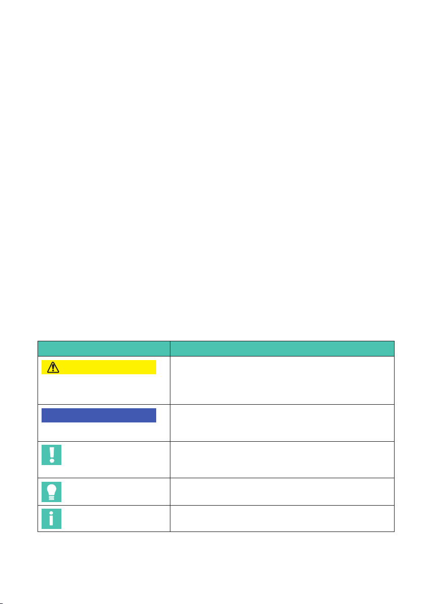
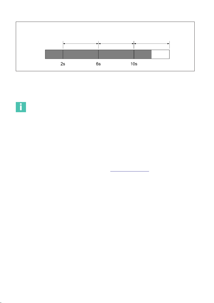
3.5 Switching OFF
To avoid accidental shut-down of the interrogator, it is necessary to press the “ON/OFF"
button between 2 and 6 seconds (Fig. 3.4).
If for some reason the 6 seconds are exceeded the user can release the button before 10
seconds are reached and the interrogator will remain ON (Fig. 3.5).
Notice
If the ON/OFF button is pressed more than 10 seconds irreversible changes on the interro
gator configuration are performed.
POWER LED
blinking at 1 Hz
Fig. 3.4 Power LED while pressing Switching Off between 2 s and 6 s
FS22SI
OPERATION
16
POWER LED
blinking at 1 Hz
POWER LED
ON
Fig. 3.5 Power LED while pressing Switching Off between 6 s and 10 s
3.6 Operating the Interrogator
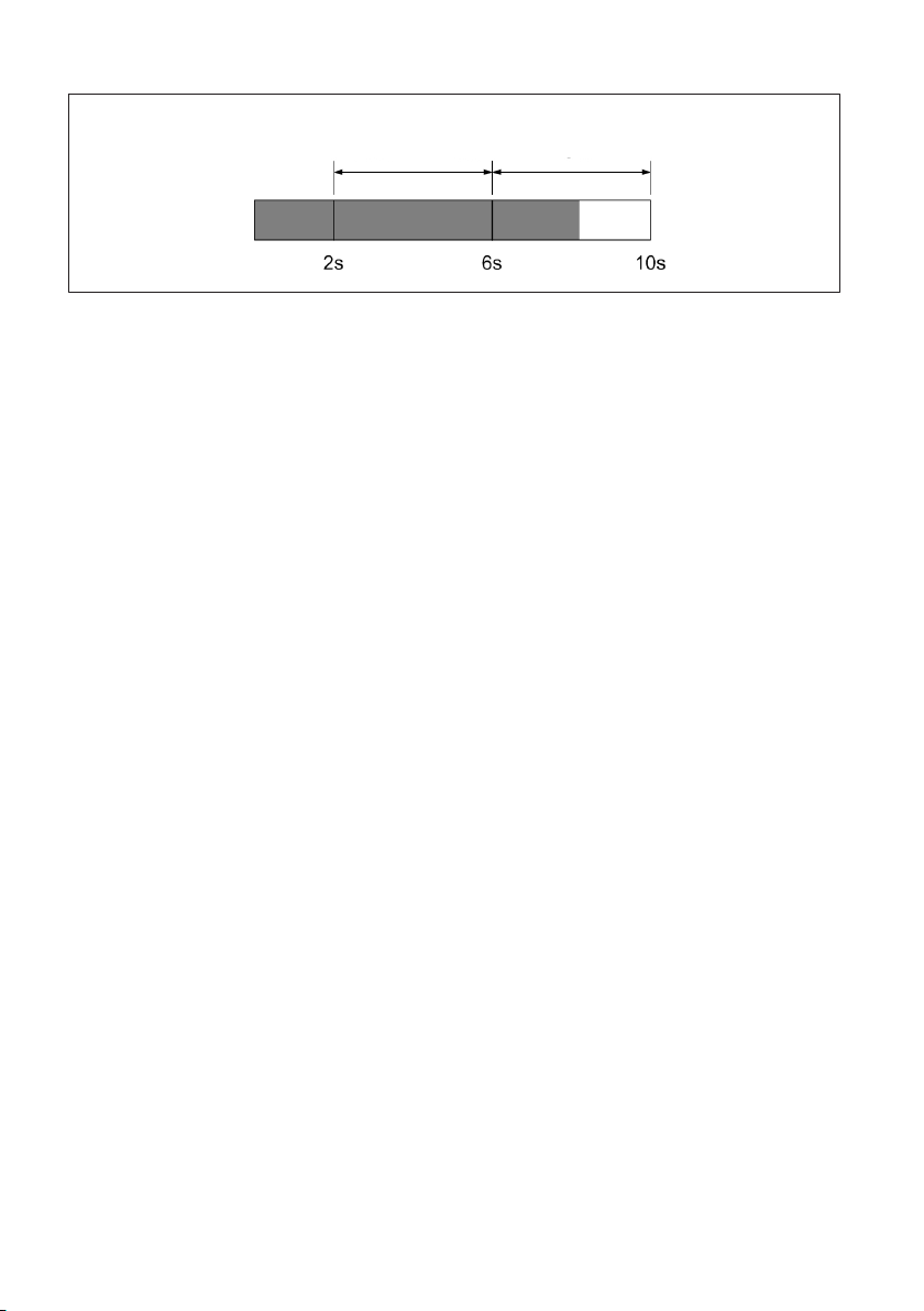
3.6.1 Network Properties
To operate the FS22 - Industrial BraggMETER SI from a personal computer, the PC net
work properties should be set so that both elements are configured in the same subnet.
To configure your personal computer so that it is on the same subnet as the default for
the interrogator, proceed as follows:
uOn the control panel choose Network Connections.
uSelect the LAN connection. The window displayed in Fig. 3.6 will appear. Click on
Properties.

FS22SI
OPERATION
18
Fig. 3.7 Local Area connection properties

19
FS22SI
OPERATION
uSet the IP address and the subnet mask as in Fig. 3.8.
Fig. 3.8 Internet Protocol Version 4 Properties
uPress OK.
3.6.2 Resetting the IP Address of the Interrogator
If for any chance there is the need to physically change the IP address of the interrogator,
there is a reset procedure that consists on pressing the ON/OFF button for more than
10 seconds.
When the button is being pressed for 10 seconds the POWER LED blinks 3 times and
goes OFF. At this moment the ON/OFF button can be released and the reset of IP address
will happen.
FS22SI
OPERATION
20
POWER LED
blinking at 1 Hz
POWER LED
ON
POWER LED
blinks 3 times
and goes OFF
Fig. 3.9 Power LED while pressing Switching Off for more than 10 s
This procedure resets the interrogator changing its IP address to the default and its mea
suring settings to the last stored.
Information
The interrogator default network properties are “10.0.0.10:255.0.0.0:0.0.0.0".
3.6.3 Synchronization
In order to achieve synchronous measurements between different devices the NTP (Net
work Time Protocol) synchronization via Ethernet must be used.
Each optical Interrogator can synchronize its internal clock with an NTP server. It is possi
ble to achieve accuracies of 1ms or higher, depending on whether or not a dedicated NTP
server is being used.
Further information about NTP can be found at http://www.ntp.org.
Measuring Systems Typology
A measurement system can be as simple as a single interrogator or a bit more complex
with combined interrogators with the same or different sampling rates, and interrogators
combined with other equipment.
For the usage of a single interrogator no special synchronization
is needed.
BraggMONITOR SI software can only operate one interrogator at
a time. If an NTP server is running on the same PC as the Brag
gMONITOR SI, the interrogator internal clock – hence Brag
gMONITOR SI – will sync.
If more than one interrogator is used, synchronization becomes
important and if an NTP server is running the equipment will
start synching as soon as a first communication from the server
is received.
Single interrogator
Multiple
interrogators
Table of contents
Other HBK Measuring Instrument manuals


