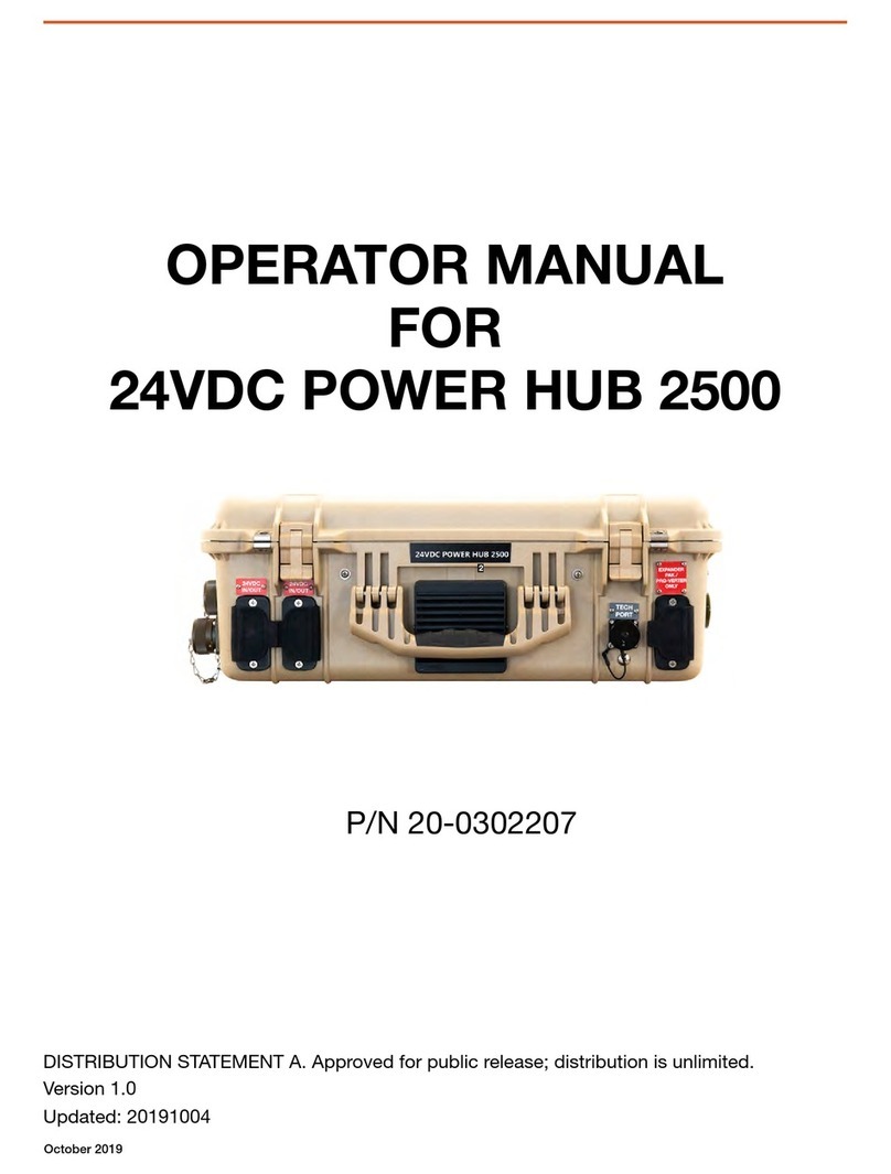
Solar Stik 24VDC HyPR 3000 Installation instructions

|1April 2021 |Solar Stik®, Inc. PRELIMINARY DRAFT
24VDC HyPR 3000 Operator and Maintenance Manual
Operator and Maintenance Manual
for the
24VDC HyPR 3000
Version 1.0
Updated:20210413
DISTRIBUTION STATEMENT A. Approved for public release; distribution is unlimited.

April 2021 |Solar Stik®, Inc.2 |
24VDC HyPR 3000 Operator and Maintenance Manual
PRELIMINARY DRAFT
Contents
GENERAL INFORMATION, EQUIPMENT DESCRIPTION, AND THEORY OF OPERATION
Introduction . . . . . . . . . . . . . . . . . . . . . . . . . . . . . . . . . . . . . . . . . . . . . . . . . . . . . 5
Requirements for HyPR Operation . . . . . . . . . . . . . . . . . . . . . . . . . . . . . . . . . . . . . . . . .5
HyPR 3000 Capabilities and Controls . . . . . . . . . . . . . . . . . . . . . . . . . . . . . . . . . . . . . . . 6
User Control Functions . . . . . . . . . . . . . . . . . . . . . . . . . . . . . . . . . . . . . . . . . . . . . . . 6
Data Management . . . . . . . . . . . . . . . . . . . . . . . . . . . . . . . . . . . . . . . . . . . . . . . . . . 6
Theory of Operation
General Information . . . . . . . . . . . . . . . . . . . . . . . . . . . . . . . . . . . . . . . . . . . . . . . . . 8
AC Functions . . . . . . . . . . . . . . . . . . . . . . . . . . . . . . . . . . . . . . . . . . . . . . . . . . . . . 8
Charging . . . . . . . . . . . . . . . . . . . . . . . . . . . . . . . . . . . . . . . . . . . . . . . . . . . . . 8
Inverting . . . . . . . . . . . . . . . . . . . . . . . . . . . . . . . . . . . . . . . . . . . . . . . . . . . . . . 8
DC Functions . . . . . . . . . . . . . . . . . . . . . . . . . . . . . . . . . . . . . . . . . . . . . . . . . . . . .9
Solar Power . . . . . . . . . . . . . . . . . . . . . . . . . . . . . . . . . . . . . . . . . . . . . . . . . . . . 9
Power Scavenging . . . . . . . . . . . . . . . . . . . . . . . . . . . . . . . . . . . . . . . . . . . . . . . . 9
Auto Generator Start / Stop . . . . . . . . . . . . . . . . . . . . . . . . . . . . . . . . . . . . . . . . . . . 10
Load Prioritization . . . . . . . . . . . . . . . . . . . . . . . . . . . . . . . . . . . . . . . . . . . . . . . . . 11
Modes of Operation . . . . . . . . . . . . . . . . . . . . . . . . . . . . . . . . . . . . . . . . . . . . . . . . 12
Selecting an AC Power Source . . . . . . . . . . . . . . . . . . . . . . . . . . . . . . . . . . . . . . . . . . 15
Energy Storage Requirements for Operation . . . . . . . . . . . . . . . . . . . . . . . . . . . . . . . . . . 15
Battery Low-voltage Cut Off (LVCO) . . . . . . . . . . . . . . . . . . . . . . . . . . . . . . . . . . . . . . . 15
Battery Current Requirements for HyPR AC Output . . . . . . . . . . . . . . . . . . . . . . . . . . . . . . 16
Temperature-dependent Power Processing. . . . . . . . . . . . . . . . . . . . . . . . . . . . . . . . . . . 16
Derating Specications . . . . . . . . . . . . . . . . . . . . . . . . . . . . . . . . . . . . . . . . . . . . . 16
How to Minimize Derating . . . . . . . . . . . . . . . . . . . . . . . . . . . . . . . . . . . . . . . . . . . . 17
Important Safety Information and Instructions . . . . . . . . . . . . . . . . . . . . . . . . . . . . . . . . . 18
Safety Information Labels . . . . . . . . . . . . . . . . . . . . . . . . . . . . . . . . . . . . . . . . . . . . 18
Fire Hazard . . . . . . . . . . . . . . . . . . . . . . . . . . . . . . . . . . . . . . . . . . . . . . . . . . . 19
Recommended Fire Extinguisher . . . . . . . . . . . . . . . . . . . . . . . . . . . . . . . . . . . . . . . . 19
Electric Shock Hazard. . . . . . . . . . . . . . . . . . . . . . . . . . . . . . . . . . . . . . . . . . . . . . 20
Environmental and Handling Precautions . . . . . . . . . . . . . . . . . . . . . . . . . . . . . . . . . . . . 21
Water . . . . . . . . . . . . . . . . . . . . . . . . . . . . . . . . . . . . . . . . . . . . . . . . . . . . . . 21
Impact . . . . . . . . . . . . . . . . . . . . . . . . . . . . . . . . . . . . . . . . . . . . . . . . . . . . . . 21
Dust/Foreign Object Intrusion . . . . . . . . . . . . . . . . . . . . . . . . . . . . . . . . . . . . . . . . . . 21
Heat . . . . . . . . . . . . . . . . . . . . . . . . . . . . . . . . . . . . . . . . . . . . . . . . . . . . . . . 21
The Inter-Connect System . . . . . . . . . . . . . . . . . . . . . . . . . . . . . . . . . . . . . . . . . . . . 22
24VDC Linear Inter-Connect Cable . . . . . . . . . . . . . . . . . . . . . . . . . . . . . . . . . . . . . . . 23
The Standard Inter-Connect Plug . . . . . . . . . . . . . . . . . . . . . . . . . . . . . . . . . . . . . . . . 23
EQUIPMENT DESCRIPTION
Introduction . . . . . . . . . . . . . . . . . . . . . . . . . . . . . . . . . . . . . . . . . . . . . . . . . . . . 24
Information Plate (I-Plate) . . . . . . . . . . . . . . . . . . . . . . . . . . . . . . . . . . . . . . . . . . . . . 25
AC Power Input Port . . . . . . . . . . . . . . . . . . . . . . . . . . . . . . . . . . . . . . . . . . . . . . . . 26
Solar Input Port . . . . . . . . . . . . . . . . . . . . . . . . . . . . . . . . . . . . . . . . . . . . . . . . . . 26
Power Scavenging Port . . . . . . . . . . . . . . . . . . . . . . . . . . . . . . . . . . . . . . . . . . . . . . 27
Expander Pak Only Port . . . . . . . . . . . . . . . . . . . . . . . . . . . . . . . . . . . . . . . . . . . . . 28
24 VDC IN/OUT Ports . . . . . . . . . . . . . . . . . . . . . . . . . . . . . . . . . . . . . . . . . . . . . . . 29

|3April 2021 |Solar Stik®, Inc. PRELIMINARY DRAFT
24VDC HyPR 3000 Operator and Maintenance Manual
120 VAC OUTPUT Ports . . . . . . . . . . . . . . . . . . . . . . . . . . . . . . . . . . . . . . . . . . . . . . 29
GEN COMM Ports . . . . . . . . . . . . . . . . . . . . . . . . . . . . . . . . . . . . . . . . . . . . . . . . . 30
Cooling Vents. . . . . . . . . . . . . . . . . . . . . . . . . . . . . . . . . . . . . . . . . . . . . . . . . . . . 30
Faceplate . . . . . . . . . . . . . . . . . . . . . . . . . . . . . . . . . . . . . . . . . . . . . . . . . . . . . . 31
DC Interface . . . . . . . . . . . . . . . . . . . . . . . . . . . . . . . . . . . . . . . . . . . . . . . . . . . . 33
Solar Charging Status LED . . . . . . . . . . . . . . . . . . . . . . . . . . . . . . . . . . . . . . . . . . . 33
AC Interface . . . . . . . . . . . . . . . . . . . . . . . . . . . . . . . . . . . . . . . . . . . . . . . . . . . . 34
AC Input Control Dial . . . . . . . . . . . . . . . . . . . . . . . . . . . . . . . . . . . . . . . . . . . . . . 34
Generator Control Switches . . . . . . . . . . . . . . . . . . . . . . . . . . . . . . . . . . . . . . . . . . . 34
Breakers / Switches Panel . . . . . . . . . . . . . . . . . . . . . . . . . . . . . . . . . . . . . . . . . . . . 35
AC Output Status LED . . . . . . . . . . . . . . . . . . . . . . . . . . . . . . . . . . . . . . . . . . . . . . . 35
Connecting Generators to HyPR . . . . . . . . . . . . . . . . . . . . . . . . . . . . . . . . . . . . . . . . . 36
Compatible Generator Options . . . . . . . . . . . . . . . . . . . . . . . . . . . . . . . . . . . . . . . . . 36
HyPR GEN COMM Port Specicity . . . . . . . . . . . . . . . . . . . . . . . . . . . . . . . . . . . . . . . 37
MPG Parallel Connections . . . . . . . . . . . . . . . . . . . . . . . . . . . . . . . . . . . . . . . . . . . 39
Operator Instructions
HyPR Setup and Operation . . . . . . . . . . . . . . . . . . . . . . . . . . . . . . . . . . . . . . . . . . . . 40
Navigating DC User Interface Menus . . . . . . . . . . . . . . . . . . . . . . . . . . . . . . . . . . . . . . 41
Programmable Parameters . . . . . . . . . . . . . . . . . . . . . . . . . . . . . . . . . . . . . . . . . . . . 42
Maintenance
Preventive Maintenance Checks and Services (PMCS) . . . . . . . . . . . . . . . . . . . . . . . . . . . . 43
HyPR 3000 Air Intake Filter Cleaning. . . . . . . . . . . . . . . . . . . . . . . . . . . . . . . . . . . . . . . 43
Water Intrusion Remediation . . . . . . . . . . . . . . . . . . . . . . . . . . . . . . . . . . . . . . . . . . . 45
Transporting the HyPR 3000 . . . . . . . . . . . . . . . . . . . . . . . . . . . . . . . . . . . . . . . . . . . 45
TECHNICAL SPECIFICATIONS
ABOUT SOLAR STIK, INC.
Contact . . . . . . . . . . . . . . . . . . . . . . . . . . . . . . . . . . . . . . . . . . . . . . . . . . . . . . . 47

April 2021 |Solar Stik®, Inc.4 |
24VDC HyPR 3000 Operator and Maintenance Manual
PRELIMINARY DRAFT
List of Figures
Figure 1. Schematized power ow from a top-down view of the interior of the HyPR 3000 ........................................... 7
Figure 2. Using the HyPR 3000 in Hybrid Model............................................................................................................ 12
Figure 3. Using the HyPR 3000 in UPS Model ............................................................................................................... 12
Figure 4. Using HyPR in Power Conditioning Model...................................................................................................... 13
Figure 5. Using HyPR in Scavenge Model...................................................................................................................... 13
Figure 6. Using HyPR in Inverter Mode .......................................................................................................................... 14
Figure 7. Linear Inter-Connect Plug................................................................................................................................ 23
Figure 8. Inter-Connect Plug .......................................................................................................................................... 23
Figure 9. 24 VDC HyPR 3000 connections..................................................................................................................... 24
Figure 10. HyPR 3000 AC power input port................................................................................................................... 26
Figure 11. HyPR 3000 solar input port ........................................................................................................................... 26
Figure 12. HyPR 3000 DC power scavenging port......................................................................................................... 27
Figure 13. HyPR Expander Expander Pak / ESM connection port ................................................................................ 28
Figure 14. HyPR 24 VDC input / output ports ................................................................................................................ 29
Figure 15. HyPR 120 VAC output ports.......................................................................................................................... 29
Figure 17. Expander Pak generator communications ports........................................................................................... 30
Figure 16. HyPR 3000 cooling vents .............................................................................................................................. 30
Figure 18. 24 VDC HyPR 3000 Faceplate ...................................................................................................................... 31
Figure 19. HyPR 3000 DC INTERFACE .......................................................................................................................... 33
Figure 22. AC Input Control dial ..................................................................................................................................... 34
Figure 20. Generator mode control switches and LEDs................................................................................................. 34
Figure 21. Generator Status LED blinking pattern.......................................................................................................... 34
Figure 23. HyPR 3000 breakers...................................................................................................................................... 35
Figure 24. HyPR Inverter / AC OUTPUT status LED ...................................................................................................... 35
Figure 26. Connecting generators to HyPR.................................................................................................................... 36
Figure 25. Compatible generator options....................................................................................................................... 36
Figure 27. MEP-831A and MEP-802A Gen Comm Cable connections ......................................................................... 37
Figure 28. Defender 1 kW and Ranger 2 kW Gen Comm Cable connections ............................................................... 38
Figure 29. Connecting two 1 kW generators in parallel with the “Y” AC power cable................................................... 39
Figure 30. Navigating the DC Interface .......................................................................................................................... 41
Figure 31. Abbreviated HyPR DC Interface Menu Map.................................................................................................. 42
Figure 32. Fastener locations on vent shroud ................................................................................................................ 43
Figure 33. Replacing HyPR air intake lter (left); cleaning a HyPR air intake lter (right) ............................................... 44
Figure 35. HyPR human transportation. ......................................................................................................................... 45
Figure 34. Drain plug screw located under the TECH PORT.......................................................................................... 45
List of Tables
Table 1. Charge Status Indicator—LED Status............................................................................................................... 33
Revision History
Section Page(s) Description Date
First released as a PRELIMINARY DRAFT 30 March 2021

|5April 2021 |Solar Stik®, Inc. PRELIMINARY DRAFT
24VDC HyPR 3000 Operator and Maintenance Manual
GENERAL INFORMATION, EQUIPMENT DESCRIPTION,
AND THEORY OF OPERATION
Introduction
A Hybrid Power Router (HyPR) is a power management device which processes and routes a variety
of power inputs to both DC and AC power outputs.
The HyPR is a modular, portable component of the Solar Stik Architecture and its design and exible
function affords the operator a “multi-tool” for applications demanding a singular power solution to
meet specic, and evolving, mission requirements.
Some features of the HyPR include:
• The ability to act as the primary power management device in a Hybrid Power System (HPS) or as
a supplemental power manager in AC, DC, or AC/DC systems.
• The ability to work in concert with additional power management devices when high-power or
individual control over multiple loads/voltages is required (eg. PRO-Verters).
• Support of simultaneous AC and DC outputs.
• Plug and play compatibility with the Solar Stik Inter-Connect circuit.
• Efcient management of available power to loads.
This manual provides operation and safety information for the HyPR 3000. The HyPR 3000 has been
designed specically to support Hybrid, UPS, Power Conditioning, and Scavenging requirements.
When operating the HyPR within a system, consult the I-Plate and the System Manual for specic
operation guidelines.
Requirements for HyPR Operation
• Total power INPUT must exceed total power OUTPUT in any particular operation mode.
• The HyPR requires the presence of battery (DC bus) voltage to operate at its full rated power.
• Based on the application, the user must congure the system so there is “balanced” operation
between the HyPR’s internal functions.
All HyPRs accept universal (85–264 VAC) single-phase AC input voltage, allowing connection to
any generator or grid AC power source. It is ideally suited for use where available AC power quality
is poor or AC line voltages vary. AC and DC cables for the HyPR are sold separately, as they must
match voltage type and associated current-conducting ability.

April 2021 |Solar Stik®, Inc.6 |
24VDC HyPR 3000 Operator and Maintenance Manual
PRELIMINARY DRAFT
HyPR 3000 Capabilities and Controls
The HyPR features specic capabilities for the system in which it is employed and, while many of the
circuits in the HyPR are fully automatic, outside user-established limits, not every HyPR feature may
be used in every application.
Most functions and modes are controlled by programmable settings at the User Interface(s).
• “Functions” are related to specic circuits or hardware in the HyPR.
• “Modes” refer to the operational employment of the HyPR circuits.
The faceplate is divided into two interfaces; the AC and the DC control panels:
• The HyPR AC INTERFACE panel provides complete AC circuit input and output control.
• The HyPR DC INTERFACE panel provides complete DC control, including complete circuit data
and metering.
When the main power breaker switch is turned on:
• The HyPR DC INTERFACE will power up and report DC bus voltage and amperage data on the
home screen.
• The inverter (DC>AC) will be active, but only operational once the HyPR AC OUTPUT breaker is
engaged.
• The converter (AC>DC) will be active, but only operational once the HyPR AC INPUT breaker is
engaged.
• The HyPR solar charge controller will be active, but only able to process PV power once the
SOLAR INPUT breaker is engaged.
• The HyPR DC>DC converter (scavenger) will be active, but only able to process DC power once
the 9-36 VDC INPUT breaker is engaged.
Data Management
• The DC INTERFACE provides complete DC circuit data only when an active PV array is
connected.
• The HyPR DC Interface provides basic DC circuit data, including ESM/bus voltage and net
current only when active ESMs are connected.
• If no ESMs are connected to the HyPR, then only the DC bus voltage is available from the HyPR
DC INTERFACE.
• DC bus voltage is the only accurately-reported metric from the HyPR DC INTERFACE when
ESMs are not connected.
User Control Functions

|7April 2021 |Solar Stik®, Inc. PRELIMINARY DRAFT
24VDC HyPR 3000 Operator and Maintenance Manual
Figure 1. Schematized power ow from a top-down view of the interior of the HyPR 3000
Theory of Operation
The HyPR 3000 coordinates the support of AC and DC loads using power supplied from AC and/
or DC sources. Both AC and DC power sources energize the HyPR 3000 internal DC circuitry (DC
bus), or the “Inter-Connect” circuit. The presence of DC bus voltage (battery voltage) enables the full
function of the HyPR 3000 internal circuits. System voltage and net current can be monitored on the
DC User Interface. However, it will report only a negative current value if no PV array is connected.
A schematized illustration of the DC bus and its relationship to internal components, inputs and
outputs is shown below. The arrows indicate the ow of current in the circuits.
Solar/DC Input
AC Input
24 VDC bus/Inter-Connect System
9-36 VDC Scavenge
85-265 VAC,
47-63 Hz
24 VDC
Inter-Connect
Port
120 VAC
60 Hz
PV
Input
24 VDC
IN/OUT
NATO port
solar
charge
controller
AC-
powered
DC charger
9-36
VDC
Expander
Paks
Inverter
DC buck/boost
charger
Breaker “location”
Direction of current ow
Meter/Shunt

April 2021 |Solar Stik®, Inc.8 |
24VDC HyPR 3000 Operator and Maintenance Manual
PRELIMINARY DRAFT
General Information
Circuit breakers on faceplate are only for IN/OUT circuit limit protections. They are NOT “function
controls” or “function protections”.
The internal DC Bus is limited to 100 A total current ow. This may restrict some HyPR functionality
in certain operating modes.
Current ow on the DC bus is controlled by voltage. Power will always be prioritized to the loads and
will only cease when the voltage drops to low-voltage disconnects located within the inverter (AC
loads), the ESMs and DC Interface (DC loads).
24 VDC IN/OUT NATO and 24VDC IN/OUT ports operate directly from the internal DC bus. Power
in/out of these ports will only be reected in the “net” current in/out of the ESMs when a PV array is
connected.
System recovery from overdischarged batteries is possible using AC power or alternative 24 VDC
power sources. System recovery using PV power is not an option.
Inverter “continuous AC power output” uctuates based on conditions such as temperature (heat
derating = efciency loss).
AC Functions
The HyPR employs two (2) separate AC functions that operate on the DC bus:
Charging
AC>DC converter provides up to 100 A at 29 V DC to the DC bus (~3000 W).
Inverting
DC>AC inverter removes up to 84 A at 24 VDC from the internal DC bus (~2000 W).
When conguring the HyPR for use, it is important to understand how to establish balance between
the power available from sources and the power required by the loads.
When using AC power sources in Hybrid or UPS models, the AC INPUT setting must be set for the
following conditions:
• continuity of AC load operation
• battery charging
• not to exceed the power output of the AC source
When small expeditionary generators are used, the HyPR can be used for dynamic loads that would
normally cause overloading of the generator.

|9April 2021 |Solar Stik®, Inc. PRELIMINARY DRAFT
24VDC HyPR 3000 Operator and Maintenance Manual
DC Functions
The DC bus is effectively the nervous system of the HyPR. All HyPR functions are regulated directly
or indirectly by the DC bus voltage. The DC bus voltage is functionally equivalent to the System
battery voltage. Direct connections to the DC bus can be made via the two (2) Inter-Connect ports
and the NATO port. Ports for PV, the scavenger circuit, AC Input and AC output ports are indirect
connections to the DC bus (See “Figure 1. Schematized power ow from a top-down view of the
interior of the HyPR 3000” on page 7).
DC power will ow into or out of the HyPR via the direct connections (Inter-Connect and NATO
ports).
The indirect connections allow power to ow to the bus after being altered from its original form, for
example:
• 30-57 VDC power from PV arrays converted by the solar charge controller to 29.0 VDC
• 9-36 VDC scavenged power converted to 28.4 VDC
• AC power converted to 28.2 VDC
• Inverter converts energy stored in batteries to 120 VAC power output.
Utilization of power sources to charge batteries and support loads is prioritized by voltage.
Prioritizing PV and scavenged DC power over AC power reduces reliance on fuel-powered
generators.
Solar Power
The SOLAR INPUT port is the only port that may be used to connect PV power to the HyPR.
Connecting a PV array to any other input port will damage to the HyPR.
Any PV array input must meet the following specications: 400 W or less, voltage between 30 and 57
VDC, and a maximum current rating of 15 A at 24 VDC.
The HyPR converts incoming PV power to a 29.0 VDC charging current. When multiple power inputs
are present, 29.0 VDC PV power is automatically prioritized for battery charging.
When a PV array is present, all features of the HyPR DC INTERFACE are available. If PV power is not
an integral part of a HyPR 3000-based System, only the voltage and current metrics on the home
screen are accurate while the System is operating.
Power Scavenging
Scavenged power is converted to 28.4 VDC charging voltage placing it second, after PV power,
in the rank order of prioritization of power sources. Therefore if PV power is present, scavenged
sources may not contribute to the charging current on the bus.
The scavenged power source must be able to provide at least 250 W of power. Total Internal power
consumption of the HyPR is ~100 W. If passing power through to a load when in Scavenge mode,
then only about 150 W will be available for use.

April 2021 |Solar Stik®, Inc.10 |
24VDC HyPR 3000 Operator and Maintenance Manual
PRELIMINARY DRAFT
Drawing power from a vehicle battery in scavenge mode has the potential to overdischarge the
vehicle starter battery rapidly. Run the vehicle motor when scavenging power from a vehicle to avoid
overdischarging the starter battery.
Beware of HyPR overheating when using the power scavenging function.
Power input is limited to 150 W. Power output is limited to 100 W. Custom cables may be required.
If the load exceeds 100 W, the power supply will temporarily shut down and will not resume until
the load is reduced. The 9-36 VDC switch on the Faceplate is unlikely to trip due to the fact that the
Scavenger power supply and the inverter self protect.
Auto Generator Start / Stop
The HyPR Auto Generator Start/Stop (AGS) functions are controlled using the GENERATOR
CONTROL switches on the Faceplate.
• The ON position turns on a connected generator regardless of the DC bus voltage.
• The AUTO setting automatically starts and stops a connected generator based on DC bus
(battery) voltage.
• The OFF setting stops the generator(s) if it is running or prevents the generator from turning on.
Automatic Generator Start/Stop (AGS) voltages
The HyPR AGS is programmed to start and stop the generator(s) at voltages that allow the ESMs to
charge and discharge over a safe and efcient voltage range.
• Generator start set point = 25.5 VDC
• Generator stop set point = 29.0 VDC
The generator start and stop voltage set points are programmable via a TECH PORT on the
Faceplate. Contact Solar Stik Technical Support for assistance if reprogramming is required.

|11April 2021 |Solar Stik®, Inc. PRELIMINARY DRAFT
24VDC HyPR 3000 Operator and Maintenance Manual
Load Prioritization
In every operation mode, the HyPR will prioritize power to the load. It executes functions based on
real-time operating conditions, which include:
• total power available at the INPUTS
• total power needed at the OUTPUTS
• battery SOC
• temperature
• user programming for special conditions
HyPRs can be used with grid-utility or generator AC power, and can easily be adjusted to operate
within the current limits of both the AC load circuit and the external AC power source.
When operating a HyPR with multiple DC power sources connected (e.g., PV, Wind, vehicular, fuel
cells, etc.), all incoming power will be prioritized to the load, reducing consumption of energy stored
in the batteries, thereby extending battery-only runtime and the reducing need for AC power from a
grid-utility or generator source.
When operating a HyPR with a fuel-driven generator(s), the AGS circuit can be used to start the
generator(s) when the battery SOC is low. Once the battery SOC reaches a user-determined point,
the HyPR AGS circuit will start the generator, ensuring power to the load. In effect, the HyPR uses a
connected generator as the last line of defense against mission failure.
With load prioritization, the load will always be the rst to receive power. Any incoming power not
consumed by the load is stored in the batteries. Stored energy is for use to support loads when
these inputs are not available (e.g., grid failure, generator maintenance periods, etc.) and to reduce
reliance on fuel-powered generators.

April 2021 |Solar Stik®, Inc.12 |
24VDC HyPR 3000 Operator and Maintenance Manual
PRELIMINARY DRAFT
Generator
Solar
Energy Storage
Loads
AC
9-36 VDC
Scavenge
Hybrid Mode–The hybrid mode allows the use of a smaller generator based on average, continuous
total loads over a 24-hour period, versus a larger generator that will support “peak” loads, which are
usually momentary or short in duration:
• AC power generation source (Ranger/Defender, TQG) with ESMs
• DC power generation source (PV, scavenging) with ESMs
• AC and DC power generation sources (combinations of the above) with ESMs
AC Power Limits
3000 W AC Input from source(s)
2000 W AC Output for loads
Modes of Operation
UPS Mode–The HyPR 3000 is capable of operating as an Uninterruptible Power Supply/Source,
providing instantaneous emergency power to a load in the event that primary power source fails. In
this mode, the HyPR 3000 will to provide power to the load until it can be turned off safely or until
primary power is restored. In this mode, power duration is limited to that contained in the ESM’s
connected to the HyPR 3000.
• AC utility / grid power sources with ESMs
• ESMs do not cycle
Figure 2. Using the HyPR 3000 in Hybrid Model
Grid
Energy Storage
Loads
AC
AC Power Limits
3000 W AC Input from source(s)
2000 W AC Output for loads
Figure 3. Using the HyPR 3000 in UPS Model
There are several operational modes in which the HyPR may be congured, depending on the
application,

|13April 2021 |Solar Stik®, Inc. PRELIMINARY DRAFT
24VDC HyPR 3000 Operator and Maintenance Manual
Power Conditioning Mode–The HyPR 3000 has a power conditioning mode that stabilizes output
voltage and frequency from dirty AC power sources. The HyPR will convert AC power with voltage
ranging from 85-264 and frequencies between 47-63 Hz into clean, pure sine wave 120 VAC, 60 Hz
power providing protection for sensitive loads:
• HyPR with ESMs between AC power sources and AC and DC loads - eliminates overloading
of small expeditionary generators and increases the HyPR power output stability over longer
periods of time.
• HyPR without ESMs between AC power sources and AC and DC loads - eliminates AC power
source voltage and frequency uctuations that can cause problems with sensitive electronic
loads.
Grid
With or without
Energy Storage
Loads
AC
Generator
or
AC Power Limit
1500W with ESMs
1000W without ESMs
Figure 4. Using HyPR in Power Conditioning Model
With or without
Energy Storage
Loads
AC
9-36 VDC
Scavenge
DC Scavenging Mode–The HyPR 3000 provides an energy scavenging tool to harvest power from
conventional and non-conventional 9 to 36-volt power sources not integral to the Solar Stik family of
products, such as a random batteries or a 12 VDC vehicle accessory outlet. The HyPR scavenging
circuit automatically converts any power source voltage between 9 and 36 VDC to 28.4 VDC
which is appropriate for charging ESMs and/or to support small 120 VAC or 24 VDC loads. It is not
necessary for a Solar Stik ESM to be connected to the HPS to take advantage of the Scavenging
circuit. If ESM’s are not connected, however, the HyPR can only support loads up to the amount of
power provided through the Scavenging circuit (Figure 1).
• Scavenging with ESMs connected to HyPR allows ESMs to be charged using external batteries
or vehicle DC systems.
• Scavenging without ESMs connected to HyPR allows small loads to be operated directly from a
connection to a 12 VDC vehicle accessory outlet.
AC Power Limits
300 W with ESMs connected
150 W without ESMs connected
Figure 5. Using HyPR in Scavenge Model

April 2021 |Solar Stik®, Inc.14 |
24VDC HyPR 3000 Operator and Maintenance Manual
PRELIMINARY DRAFT
• Renewable power generation is abundant and stable.
• Scavengable DC power resources are available.
• Connection to a vehicle NATO port is available.
Inverter Mode – The HyPR 3000 may be used in inverter mode when no AC power generation
sources are available. This allows the combined total input of DC sources (including ESMs) to be
dedicated to AC loads. This mode may be used when:
ESMs Scavenge
9-36 VDC
AC Power Limits
2000 W with ESMs connected
Solar
Vehicle / Other
Loads
AC
Figure 6. Using HyPR in Inverter Mode

|15April 2021 |Solar Stik®, Inc. PRELIMINARY DRAFT
24VDC HyPR 3000 Operator and Maintenance Manual
Selecting an AC Power Source
HyPRs can be used with grid-utility or generator AC power sources, and can easily be congured to
work with the current limits of both the DC/AC power source circuits and the DC/AC load circuits.
Once the input and output power limits are congured, the HyPR regulates how much power is
delegated between these circuits, to prevent overload conditions.
Acceptable AC power sources for use with a single HyPR 3000 should provide the following:
• 1–3 kW of power
• Pure Sine Wave AC wave form output
When considering a fuel driven generator to pair with the HyPR, note that the maximum continuous
AC load should not exceed the maximum continuous output of the AC power generator (i.e.,
maximum load AC power requirement ≤ generator AC power output). Moreover, to use the HyPR in
hybrid mode, a fuel-powered generator must be compatible with Solar Stik auto generator start/stop
capabilities.
Energy Storage Requirements for Operation
The HyPR requires connection to an active 24 VDC battery to operate. There is a minimum energy
storage capacity requirement for operation of the HyPR at it’s full rated power. Consult the I-Plate
and subsequent sections of this Manual for specic information regarding minimum capacity
necessary for a particular application.
The HyPR is compatible with lead-acid and lithium battery chemistries. However, battery chemistries
should never be mixed within a System.
Battery Low-voltage Cut Off (LVCO)
AC loads
The HyPR inverter is programmed, via the DC INTERFACE AUX circuit, to cease support of AC loads
(turn off the inverter) before the System battery voltage drops to a critical, overdischarged level.
• The HyPR will discontinue the support of AC loads when System battery voltage drops to 25.0
VDC.
• The HyPR will resume support of AC loads when System battery voltage is charged backup to
25.2 VDC.
The LVCO values are set in accordance with the battery’s BMS specications and will vary
depending on the battery type and the total battery capacity in a System.
DC loads
The HyPR does NOT provide battery LVCO protections when supporting DC loads. DC loads
connected to the HyPR may draw down battery voltage to the point that the battery BMS will
disconnect the battery from service to protect it from overdischarge.

April 2021 |Solar Stik®, Inc.16 |
24VDC HyPR 3000 Operator and Maintenance Manual
PRELIMINARY DRAFT
Battery Current Requirements for HyPR AC Output
A bank of batteries with the capacity to provide > 84 amps of current is required for the HyPR
(inverter) to operate at its full rated capacity (2000 W). Battery banks with smaller current capacity
are sufcient to power up the HyPR and support loads (AC and DC) that do not exceed the current
capacity of the connected batteries.
Connecting ESMs with an insufcient current capacity to the HyPR may result in the batteries being
charged or discharged too quickly causing the battery temperature to rise to a point that the battery
management system (BMS) disconnects the batteries from the system.
Note: The total Ah capacity of all connected ESMs must be programmed, (a setting in the DC
interface), for the HyPR DC interface to report accurately, the battery state of charge.
Temperature-dependent Power Processing
The performance of all electric and electronic equipment varies with temperature with the rated
performance listed determined at standard testing conditions (77 ºF; 25 ºC). Generally performance
declines or “derates” when the equipment is operating in ambient temperatures colder or hotter than
STC; the hotter or colder the poorer the performance.
When the equipment itself generates heat, the temperature of the equipment will rise above ambient
(and STC) in direct proportion to power being processed. This too results in derating. Internal
thermostatic mechanisms are built into most equipment to reduce power processing in a heat-
dependent manner to lower heat and prevent damage. Power processing vs heat curves vary widely.
They HyPR contains two (2) major subcomponents, a charger and inverter. Both of these derate at
elevated temperatures but in a different manner. The inverter will provide full power up until a critical
temperature and then turn off, dropping the AC load then resume support of the AC load after the
inverter has cooled to a set point. The charger on the other hand, will reduce power processing at a
critical, dened temperature but continue to charge the batteries at a lower rate.
Heat absorbed by the sun (solar loading) also increases the internal temperature contributing to
temperature-dependent derating. Understanding how temperature-dependent derating affects HyPR
power processing will enable the Operator to make adjustments to ensure continuity of operations in
any environment.
Derating Specifications
The Inverter
• The inverter provides full power (2000 W) up to 86 ºF (30 ºC). It will decrease power output by
20% for each 18 ºF (10 ºC) increase over 86 ºF (30 ºC). The inverter will cease to process power
at 176 ºF (80 ºC), to self-protect, and will resume providing AC power after it cools to operating
temperature.
• Below 80 ºF (27 ºC), the HyPR can provide up to 2,000 W continuous while not charging.

|17April 2021 |Solar Stik®, Inc. PRELIMINARY DRAFT
24VDC HyPR 3000 Operator and Maintenance Manual
The Charger
• The HyPR charger provides full power (3000 W) up to ~158 ºF (30 ºC). At 158 ºF (70 ºC) it will
reduce power ~30% of full-rated power until it cools and resumes normal, full-rated output.
• Below 80 ºF (27 ºC), the HyPR can process around 2000 W continuous for battery charging (with
no loads connected).
How to Minimize Derating
• Do not overload the HyPR. Manage power processing demand by paying close attention to what
is “plugged in. Prioritize critical loads.
• Shade the HyPR 3000 to reduce solar loading. Solar Stik data indicate that solar loading of a
Pelican case can increase internal heat by ~40 ºF (~ 22 ºC) above ambient.
• Do not block airow into or out of the HyPR; give is space to breathe.
• Clean or replace the air intake lters regularly.

April 2021 |Solar Stik®, Inc.18 |
24VDC HyPR 3000 Operator and Maintenance Manual
PRELIMINARY DRAFT
Important Safety Information and Instructions
This manual contains important instructions that must be followed during the setup and operation of
a the HyPR 3000. Read all instructions and information contained in this manual.
DO NOT begin assembly or use of the HyPR 3000 without rst reading and understanding this
manual.
While the HyPR 3000 designed for indoor/outdoor operation, the user interfaces (control panels)
must not be exposed to rain, snow, moisture, or liquids. Close and latch and/or lock the cases when
the components are unattended.
Exercise caution when handling or operating the HyPR 3000. Live power may be present.
Safety Information Labels
Your safety and the safety of others is very important.
Many important safety messages have been provided in this manual and directly on the System
components. Always read and obey all safety messages.
This is the safety alert symbol. This symbol is an alert to potential hazards that can cause
death or injury. All safety messages will follow the safety alert symbol and the word
“DANGER”, “WARNING”, or “CAUTION”. These words are dened as:
DANGER Indicates a hazardous situation which, if not avoided, will result in death or
serious injury.
WARNING Indicates a hazardous situation which, if not avoided, could result in death or
serious injury.
CAUTION Indicates a hazardous situation which, if not avoided, could result in minor or
moderate injury.
All safety messages will describe what the potential hazard is, how to reduce the chance of injury,
and what can happen if the instructions are not followed.

|19April 2021 |Solar Stik®, Inc. PRELIMINARY DRAFT
24VDC HyPR 3000 Operator and Maintenance Manual
Fire Hazard
Fire Types
Class A fire - Fires in ordinary combustibles such as wood, paper, cloth, trash, and plastics.
Class B fire - Fires in ammable liquids such as gasoline, petroleum, oil, and paint.
Class C fire - Fires involving energized electrical equipment such as motors, transformers, and
appliances. Remove the power source and the class C re becomes a class A or B re.
Recommended Fire Extinguisher
NSN 4210-00-548-7219 Fire Extinguisher, Carbon Dioxide, 10 lb
Carbon dioxide is a liqueed gas, which is highly effective ghting class B and C res. These
extinguishers are ideal for areas where contamination and/or cleanup are a concern, such as data
processing centers, labs, and telecommunication rooms.
Using the Fire Extinguisher
When using the extinguisher on a re, remember PASS:
Pull the pin.
Aim the nozzle or hose at the base of the re from a safe distance.
Squeeze the operating lever to discharge the re extinguishing agent.
Sweep the nozzle or hose from side to side until the re is out. Move forward or around the re as
the re diminishes.
Watch the area for reignition until the cause has been xed.
WARNING
Only CO2(carbon dioxide) re extinguishers should
be used with this equipment.

April 2021 |Solar Stik®, Inc.20 |
24VDC HyPR 3000 Operator and Maintenance Manual
PRELIMINARY DRAFT
Electric Shock Hazard
WARNING
Standing water around the electrical equipment and/or intrusion of water into the System
components can increase the risk of electrical shock.
DON’T LET THIS BE YOU!
HIGH VOLTAGE: System components, PV
arrays, and generators may produce lethal
line voltages. Extreme care should be taken
to protect against electrocution. Always work
with another person in case an emergency
occurs. Disconnect power before performing
maintenance. Wear safety glasses whenever
working on any part of a system that requires
exposure to mechanical or direct electrical
contacts.
WARNING
The System is NOT GFCI protected.
Other manuals for 24VDC HyPR 3000
2
Table of contents
Other Solar Stik Power Supply manuals

Solar Stik
Solar Stik 24VDC PRO-VERTER 5000-220 AGS Installation manual

Solar Stik
Solar Stik PRO-Verter S 2000 AGS Manual instruction

Solar Stik
Solar Stik 24VDC PRO-VERTER 5000-120 AGS User manual

Solar Stik
Solar Stik PRO-VERTER 7000-120 User manual

Solar Stik
Solar Stik G-BOSS E LIGHT User manual

Solar Stik
Solar Stik USAF G-BOSS Manual instruction

Solar Stik
Solar Stik PRO-VERTER 5000-240 User manual

Solar Stik
Solar Stik PRO-VERTER 5000-220 AFF1 User manual

Solar Stik
Solar Stik 24VDC POWER HUB 2500 User manual

Solar Stik
Solar Stik 24VDC HyPR 3000 Installation instructions