Solar Stik 24VDC POWER HUB 2500 User manual

OPERATOR MANUAL
FOR
24VDC POWER HUB 2500
October 2019
DISTRIBUTION STATEMENT A. Approved for public release; distribution is unlimited.
Version 1.0
Updated: 20191004
P/N 20-0302207
2

24VDC Power Hub 2500 Operator Manual
October 20192 |
Contents
GENERAL INFORMATION, THEORY OF OPERATION, AND EQUIPMENT DESCRIPTION
Power Hub Introduction . . . . . . . . . . . . . . . . . . . . . . . . . . . . . . . . . . . . . . . . . . . . . . .5
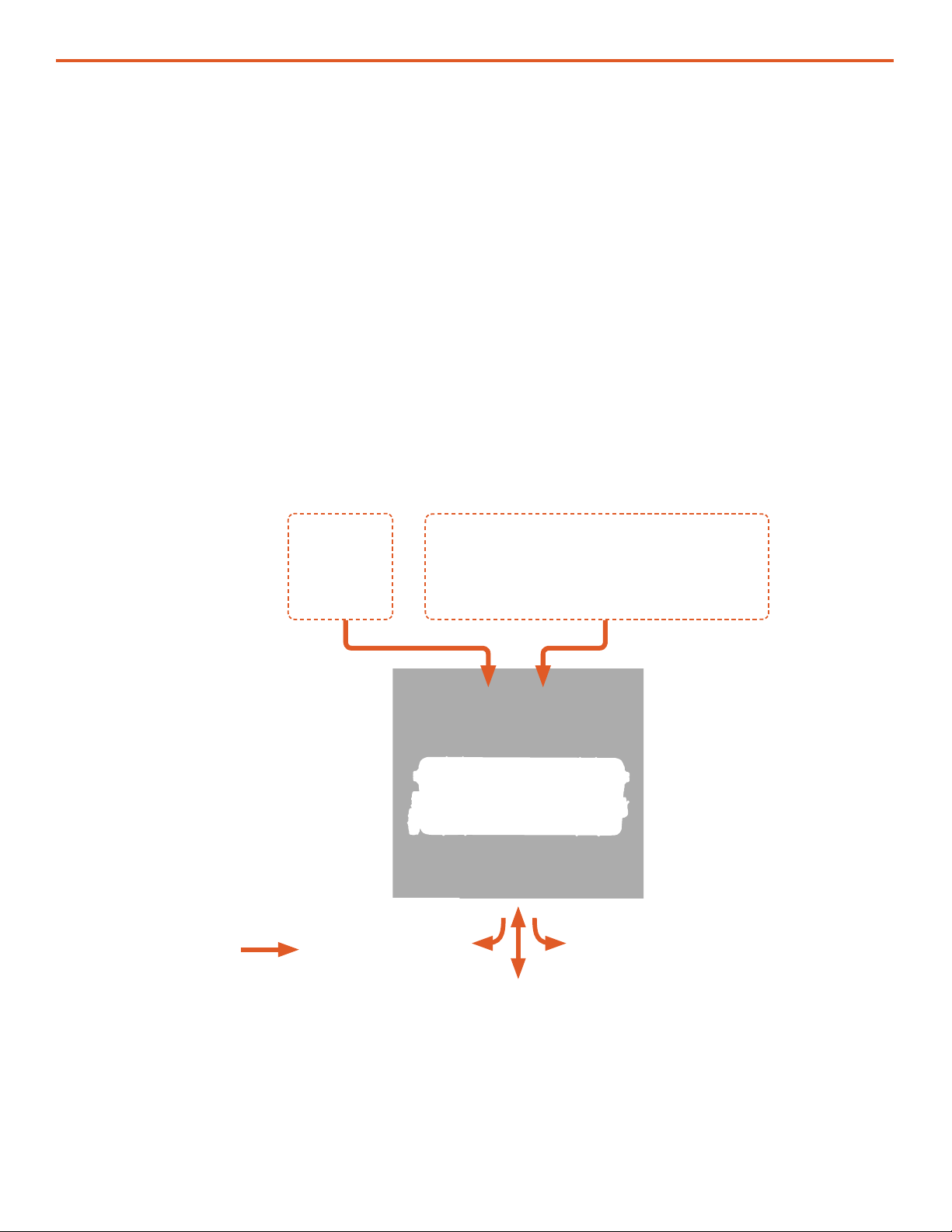
Use of the Power Hub in a System . . . . . . . . . . . . . . . . . . . . . . . . . . . . . . . . . . . . . . . . . 6
Modes of Operation . . . . . . . . . . . . . . . . . . . . . . . . . . . . . . . . . . . . . . . . . . . . . . . . . 7
Product Safety Information and Instructions . . . . . . . . . . . . . . . . . . . . . . . . . . . . . . . . . . . 7
Safety Information Labels . . . . . . . . . . . . . . . . . . . . . . . . . . . . . . . . . . . . . . . . . . . . . 8
Fire Hazard . . . . . . . . . . . . . . . . . . . . . . . . . . . . . . . . . . . . . . . . . . . . . . . . . . . . 9
Recommended Fire Extinguisher . . . . . . . . . . . . . . . . . . . . . . . . . . . . . . . . . . . . . . . . . 9
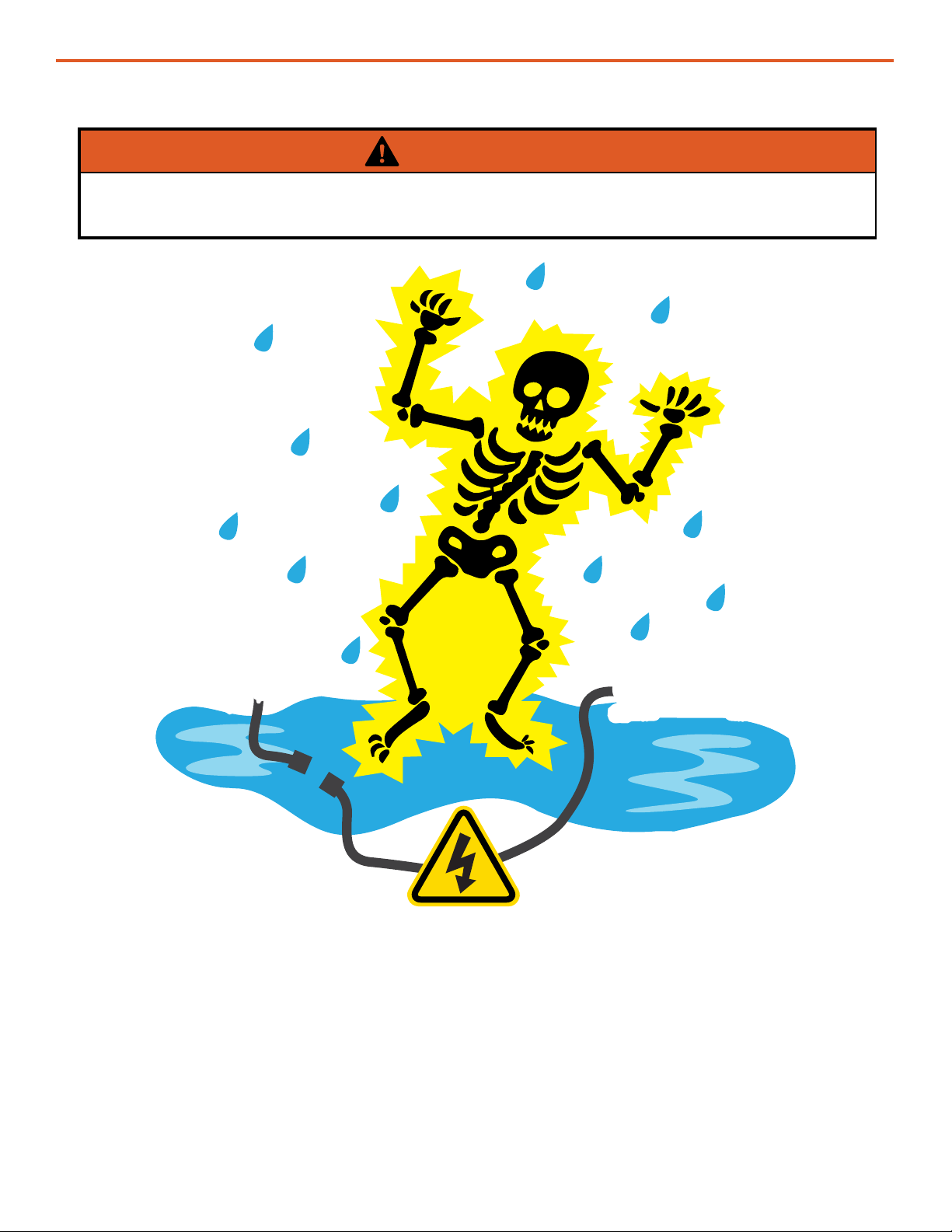
Electric Shock Hazard. . . . . . . . . . . . . . . . . . . . . . . . . . . . . . . . . . . . . . . . . . . . . . 10
Environmental and Handling Precautions . . . . . . . . . . . . . . . . . . . . . . . . . . . . . . . . . . . . 11
Water . . . . . . . . . . . . . . . . . . . . . . . . . . . . . . . . . . . . . . . . . . . . . . . . . . . . . . 11
Impact . . . . . . . . . . . . . . . . . . . . . . . . . . . . . . . . . . . . . . . . . . . . . . . . . . . . . . 11
Dust . . . . . . . . . . . . . . . . . . . . . . . . . . . . . . . . . . . . . . . . . . . . . . . . . . . . . . . 11
Heat . . . . . . . . . . . . . . . . . . . . . . . . . . . . . . . . . . . . . . . . . . . . . . . . . . . . . . . 11
THEORY OF OPERATION
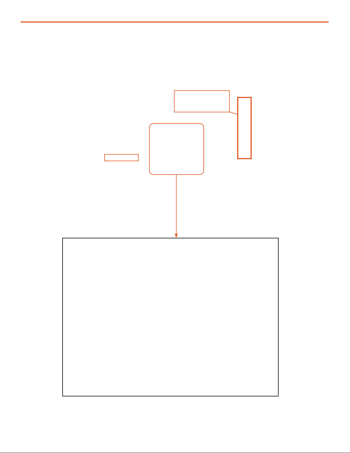
Operation Overview . . . . . . . . . . . . . . . . . . . . . . . . . . . . . . . . . . . . . . . . . . . . . . . . 12
Battery Charging and Recovery . . . . . . . . . . . . . . . . . . . . . . . . . . . . . . . . . . . . . . . . . 12
Protection Circuits. . . . . . . . . . . . . . . . . . . . . . . . . . . . . . . . . . . . . . . . . . . . . . . . 12
Metered Circuits . . . . . . . . . . . . . . . . . . . . . . . . . . . . . . . . . . . . . . . . . . . . . . . . . 13
Maximum Power Point Tracking (MPPT) – Charge Controls . . . . . . . . . . . . . . . . . . . . . . . . . . 13
Derating . . . . . . . . . . . . . . . . . . . . . . . . . . . . . . . . . . . . . . . . . . . . . . . . . . . . . 13
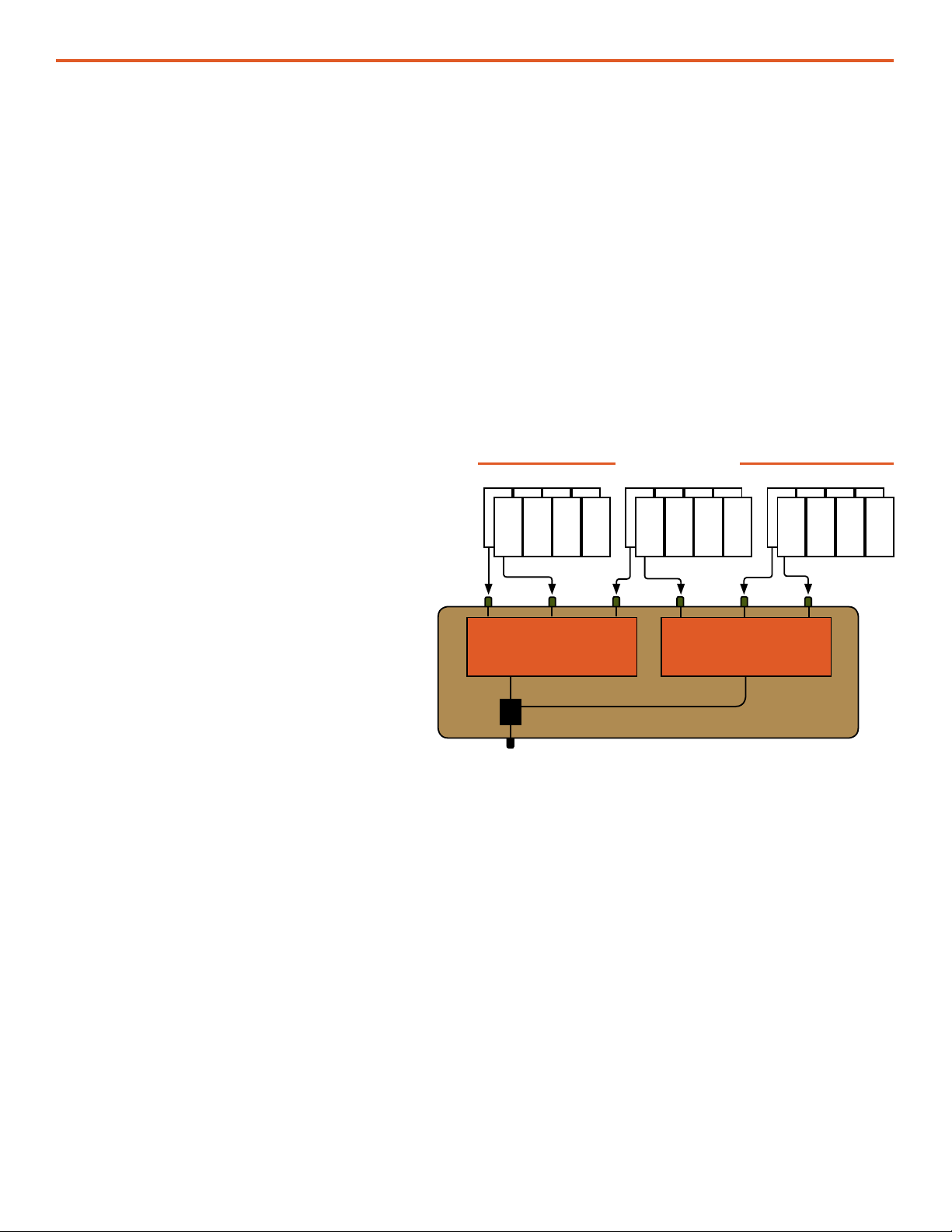
The Inter-Connect System . . . . . . . . . . . . . . . . . . . . . . . . . . . . . . . . . . . . . . . . . . . 14
Equipment Description . . . . . . . . . . . . . . . . . . . . . . . . . . . . . . . . . . . . . . . . . . . . . . 16
Connection Ports and Vents. . . . . . . . . . . . . . . . . . . . . . . . . . . . . . . . . . . . . . . . . . . 16
Internal Cooling . . . . . . . . . . . . . . . . . . . . . . . . . . . . . . . . . . . . . . . . . . . . . . . . . 18
Information Plate (I-Plate) . . . . . . . . . . . . . . . . . . . . . . . . . . . . . . . . . . . . . . . . . . . . 18
Faceplate . . . . . . . . . . . . . . . . . . . . . . . . . . . . . . . . . . . . . . . . . . . . . . . . . . . . 19
OPERATOR INSTRUCTIONS
Connections . . . . . . . . . . . . . . . . . . . . . . . . . . . . . . . . . . . . . . . . . . . . . . . . . . . . 20
Connecting PV Arrays to the Power Hub . . . . . . . . . . . . . . . . . . . . . . . . . . . . . . . . . . . . 20
Connecting Regulated 24 VDC Power Sources. . . . . . . . . . . . . . . . . . . . . . . . . . . . . . . . . 20
Connecting a 24VDC PRO-Verter or 24 VDC Expander Paks. . . . . . . . . . . . . . . . . . . . . . . . . . 21
Connecting Loads . . . . . . . . . . . . . . . . . . . . . . . . . . . . . . . . . . . . . . . . . . . . . . . . 21
Connecting to Communications Network . . . . . . . . . . . . . . . . . . . . . . . . . . . . . . . . . . . . 21
Powering up the Power Hub. . . . . . . . . . . . . . . . . . . . . . . . . . . . . . . . . . . . . . . . . . . . 21
The Power Hub User Interface . . . . . . . . . . . . . . . . . . . . . . . . . . . . . . . . . . . . . . . . . . 22
Pages Button . . . . . . . . . . . . . . . . . . . . . . . . . . . . . . . . . . . . . . . . . . . . . . . . . . 22
Menu Button. . . . . . . . . . . . . . . . . . . . . . . . . . . . . . . . . . . . . . . . . . . . . . . . . . . 23
Device List: Power Hub Circuits. . . . . . . . . . . . . . . . . . . . . . . . . . . . . . . . . . . . . . . . . 23
Monitoring PV Power: Current and Historical . . . . . . . . . . . . . . . . . . . . . . . . . . . . . . . . . . 24
PV Power: Understanding Reported Values. . . . . . . . . . . . . . . . . . . . . . . . . . . . . . . . . . . 24
Monitoring System Batteries: Current and Historical . . . . . . . . . . . . . . . . . . . . . . . . . . . . . 25
Battery Monitor: Understanding Reported Values . . . . . . . . . . . . . . . . . . . . . . . . . . . . . . . 26
Heat and Derating . . . . . . . . . . . . . . . . . . . . . . . . . . . . . . . . . . . . . . . . . . . . . . . . . 27
Causes of Overheating . . . . . . . . . . . . . . . . . . . . . . . . . . . . . . . . . . . . . . . . . . . . . 27
Power Hub Internal Cooling . . . . . . . . . . . . . . . . . . . . . . . . . . . . . . . . . . . . . . . . . . . 27

|3October 2019
24VDC Power Hub 2500 Operator Manual
Power Hub Internal Temperature Report . . . . . . . . . . . . . . . . . . . . . . . . . . . . . . . . . . . . 27
User Interface Settings Menus . . . . . . . . . . . . . . . . . . . . . . . . . . . . . . . . . . . . . . . . . . 28
Power Hub Stacking . . . . . . . . . . . . . . . . . . . . . . . . . . . . . . . . . . . . . . . . . . . . . . . . 30
Storing the Inter-Connect Cable . . . . . . . . . . . . . . . . . . . . . . . . . . . . . . . . . . . . . . . . . 31
Locking Component Cases to Prevent Tampering . . . . . . . . . . . . . . . . . . . . . . . . . . . . . . . 31
Transporting the Power Hub . . . . . . . . . . . . . . . . . . . . . . . . . . . . . . . . . . . . . . . . . . . 32
Water Intrusion Remediation . . . . . . . . . . . . . . . . . . . . . . . . . . . . . . . . . . . . . . . . . . . 32
TROUBLESHOOTING PROCEDURES
Power Hub Will Not Power Up . . . . . . . . . . . . . . . . . . . . . . . . . . . . . . . . . . . . . . . . . . 33
Performance Issues, Causes and Solutions. . . . . . . . . . . . . . . . . . . . . . . . . . . . . . . . . . . 33
Data Logging and Remote Monitoring . . . . . . . . . . . . . . . . . . . . . . . . . . . . . . . . . . . . . . 34
Performance and Troubleshooting . . . . . . . . . . . . . . . . . . . . . . . . . . . . . . . . . . . . . . . 34
Data Storage and Retrieval . . . . . . . . . . . . . . . . . . . . . . . . . . . . . . . . . . . . . . . . . . . . 34
MicroSD Card Formatting . . . . . . . . . . . . . . . . . . . . . . . . . . . . . . . . . . . . . . . . . . . . 35
Remote Monitoring . . . . . . . . . . . . . . . . . . . . . . . . . . . . . . . . . . . . . . . . . . . . . . . . 35
Solar Charge Controller Error Codes . . . . . . . . . . . . . . . . . . . . . . . . . . . . . . . . . . . . . . 37
MAINTENANCE INSTRUCTIONS
Preventive Care and Maintenance . . . . . . . . . . . . . . . . . . . . . . . . . . . . . . . . . . . . . . . . 40
Cleaning Power Hub Filters . . . . . . . . . . . . . . . . . . . . . . . . . . . . . . . . . . . . . . . . . . . 40
SUPPORTING INFORMATION
Using the Power Hub to Monitor PV Array Performance . . . . . . . . . . . . . . . . . . . . . . . . . . . . 41
Assessing PV Array Performance . . . . . . . . . . . . . . . . . . . . . . . . . . . . . . . . . . . . . . . . 41
Troubleshooting Individual PV Arrays Using the Power Hub User Interface . . . . . . . . . . . . . . . . . . 41
Specifications . . . . . . . . . . . . . . . . . . . . . . . . . . . . . . . . . . . . . . . . . . . . . . . . . . . 42

24VDC Power Hub 2500 Operator Manual
October 20194 |
List of Figures
Figure 1. A Power Hub in a Hybrid Power System........................................................................................................... 5
Figure 2. How a Power Hub works in a System............................................................................................................... 6
Figure 3. 24VDC Power Hub 2500 ................................................................................................................................... 7
Figure 4. Inter-Connect Plug .......................................................................................................................................... 15
Figure 5. Overview of Power Hub connections .............................................................................................................. 16
Figure 6. Front—DC output and communications.......................................................................................................... 16
Figure 7. Right Side—Regulated 24 VDC input and NATO connector ........................................................................... 17
Figure 8. Left Side—Solar-only ports ............................................................................................................................. 17
Figure 9. Back side—air intake vent............................................................................................................................... 18
Figure 10. Power Hub I-Plate ......................................................................................................................................... 18
Figure 11. Power Hub Faceplate features ...................................................................................................................... 19
Figure 12. Power Hub Solar Input Only connectors....................................................................................................... 20
Figure 13. Power Hub regulated 24 VDC inputs............................................................................................................. 20
Figure 14. Power Hub PRO-Verter or Expander Pak connection................................................................................... 21
Figure 15. Power Hub 24 VDC IN/OUT ports ................................................................................................................ 21
Figure 16. Power Hub Tech port..................................................................................................................................... 21
Figure 17. LCD user interface and navigation guide ...................................................................................................... 22
Figure 18. Data views displayed in “Pages”................................................................................................................... 22
Figure 19. Device list on user interface .......................................................................................................................... 23
Figure 20. Power Hub as the primary power management device ................................................................................ 26
Figure 21. Power Hub as the secondary power management device............................................................................ 26
Figure 22. Power Hub internal temperature report on user interface............................................................................. 27
Figure 23. Stacking Power Hubs.................................................................................................................................... 30
Figure 24. Inter-Connect Cable storage ......................................................................................................................... 31
Figure 25. Steel-reinforced padlock holes...................................................................................................................... 31
Figure 26. Lock securing Power Hub lid ........................................................................................................................ 31
Figure 27. Drain plug screw located under the TECH PORT.......................................................................................... 32
Figure 28. Micro SD card port location .......................................................................................................................... 34
Figure 29. Cleaning the air intake lter ........................................................................................................................... 40
Section Page(s) Description Date
First published 20191004
Revision History
List of Tables
Table 1. Symptoms and Solutions for the Most Common Power Hub Issues ............................................................... 33

|5October 2019
24VDC Power Hub 2500 Operator Manual
Power Hub Introduction
The primary function of the DC Power Hub is to serve as a singular collection, management and
distribution tool for DC power in a Hybrid Power System (HPS).
The Hub is designed specically for operation between energy-storage batteries and DC generation
sources, including photovoltaic (PV) arrays, wind generators, fuel cells, small hydro generation,
vehicular power, and more. It regulates the incoming power, making it compatible for a connected
battery, loads, or distribution devices such as inverters.
Power Hubs play a critical role in applications where any combination of the following is necessary:
• Renewable power generation is required to support a battery
• Reducing generator run-time in a hybrid system is critical
• Less reliance on grid-utility power is desirable
• DC power management and distribution is required for a battery platform
It is a modular component of the HPS architecture, and its exible design allows use with other
technologies that collectively meet specic mission requirements.
All Power Hubs are “Plug & Play”-compatible with the Inter-Connect circuit and are modular and
scalable. Their design allows multiple Power Hubs to be used in a single application where power
management requirements exceed the ability of a single Hub, or when multiple DC loads are
required to meet the demand.
The Power Hub includes one DC Inter-Connect Cable for connection to an HPS.
GENERAL INFORMATION, THEORY OF OPERATION,
AND EQUIPMENT DESCRIPTION
Figure 1. A Power Hub in a Hybrid Power System

24VDC Power Hub 2500 Operator Manual
October 20196 |
Figure 2. How a Power Hub works in a System
Use of the Power Hub in a System
The Power Hub provides a portal to integrate multiple DC power sources into a hybrid power
network, including unregulated PV power and power from regulated sources (Figure 2). It funnels all
incoming power to the batteries, PRO-Verters, or loads automatically, using basic programming in
the User Interface to direct the ow.
Programming and connection of the Hub in a System will vary according to the specic
functions the system in which it is employed, but systems vary in accordance with the operator’s
requirements. Consequently, not every feature in the Power Hub may be used for an application.
The Power Hub can support operation with either lead-acid or lithium battery types. Other changes
in programming may improve performance in extreme environmental operating conditions.
This manual provides an overview of the core features and capabilities of the Power Hub along with
a guide for the user interface menu windows. Contact your eld service representative (FSR) for
assistance in altering operation congurations or programming.
(Energy Storage Module)
24VDC Power Hub 2500
DC
(AC and DC
Loads)
24VDC PRO-Verter
Power
Management
24 VDC Li Expander Pak
Energy Storage
Wind Hydro
Fuel Cell Vehicle
Regulated DC Power Options
Unregulated
DC Power
Solar
Fuel-powered
Generator
AC
(AC and DC
Loads)
24VDC PDM Plus
Power
Management
Power
Generation
(AC Power)

|7October 2019
24VDC Power Hub 2500 Operator Manual
Modes of Operation
Depending on the application, there are several operational modes that can be congured using a
Power Hub:
• Hybrid
DC loads, DC generation and batteries are all connected to a Power Hub. It is the central power
management device in the system. The Power Hub provides constant DC power to a load by
alternating between power from batteries and power from a DC generator (such as a PV array). In the
hybrid conguration, the batteries cycle regularly, which maximizes electrical efciency throughout
the circuit, minimizing dependency on any one DC source.
• Direct DC Support
The Power Hub can be congured to provide DC into a system conguration where DC is used for
any of the following:
• Peak Shaving
• Inverter operation
• Battery charging
Product Safety Information and Instructions
This manual contains important safety instructions that must be followed during the installation
and operation of this product. Read all instructions and safety information contained in this manual
before installing or using this product.
All electrical connections must be made using the proper polarized connectors.
While this product is designed for indoor/outdoor operation, the interior of the Power Hub 2500 must
not be exposed to rain, snow, moisture, or liquids. Close and latch and/or lock the cases when the
System is unattended.
The Power Hub is not eld serviceable beyond simple preventive maintenance. Do not attempt to
open or service the unit. If repair is needed, contact your FSR.
Exercise caution when handling or operating the Power Hub. Live power may be present at more
than one point.
Figure 3. 24VDC Power Hub 2500

24VDC Power Hub 2500 Operator Manual
October 20198 |
Safety Information Labels
Your safety and the safety of others is very important.
Always read and obey all safety messages.
This is the safety alert symbol. This symbol alerts you to potential hazards that can kill you or
hurt you and others. All safety messages will follow the safety alert symbol and the word
“DANGER”, “WARNING”, or “CAUTION”. These words are dened as:
DANGER Indicates a hazardous situation which, if not avoided, will result in death or
serious injury.
WARNING Indicates a hazardous situation which, if not avoided, could result in death or
serious injury.
CAUTION Indicates a hazardous situation which, if not avoided, could result in minor or
moderate injury.
All safety messages will tell you what the potential hazard is, how to reduce the chance of injury, and
what can happen if the instructions are not followed.

|9October 2019
24VDC Power Hub 2500 Operator Manual
Use Sweeping Motion
These additional cautionary steps will ensure
your safety:
• System components should not be operated in
standing water.
• Close and latch the component lids if it is
precipitating.
• System cables should not be routed through
standing water.
• Cable connections should remain dry.
• Unused ports on System components should
be covered when not in use to reduce the
possibility of water intrusion.
Fire Hazard
Fire Types
Class A fire - Fires in ordinary combustibles such as wood, paper, cloth, trash, and plastics.
Class B fire - Fires in ammable liquids such as gasoline, petroleum, oil, and paint.
Class C fire - Fires involving energized electrical equipment such as motors, transformers, and
appliances. Remove the power source and the class C re becomes a class A or B re.
Recommended Fire Extinguisher
NSN 4210-00-288-7219 Fire Extinguisher, Carbon Dioxide, 10 lb
Carbon dioxide is a liqueed gas, which is highly effective ghting class B and C res. These
extinguishers are ideal for areas where contamination and/or cleanup are a concern, such as data
processing centers, labs, and telecommunication rooms.
Using the Fire Extinguisher
When using the extinguisher on a re, remember PASS:
Pull the pin.
Aim the nozzle or hose at the base of the re from a safe distance.
Squeeze the operating lever to discharge the re extinguishing agent.
Sweep the nozzle or hose from side to side until the re is out. Move forward or around the re as the
re diminishes.
Watch the area for reignition until the cause has been xed.
WARNING
Only CO2(carbon dioxide) re extinguishers should
be used with equipment.

24VDC Power Hub 2500 Operator Manual
October 201910 |
Electric Shock Hazard
WARNING
Standing water around the electrical equipment and/or intrusion of water into the System
components can increase the risk of electrical shock.
DON’T LET THIS BE YOU!
HIGH VOLTAGE: System components, PV arrays, and generators may have lethal line voltages.
Extreme care should be taken to protect against electrocution. Always work with another
person in case an emergency occurs. Disconnect power before performing maintenance. Wear
safety glasses whenever working on any part of a System that requires exposure to mechanical
or direct electrical contacts.

|11October 2019
24VDC Power Hub 2500 Operator Manual
Environmental and Handling Precautions
All components are ruggedized, yet there are a few things the operator can do to prevent failures
and prolong the operational life of the product.
Water
If outdoor operation is necessary, the lids
of all components should be closed and
latched whenever possible. Lids should only
be open to access operator controls and
closed at all other times.
Impact
Equipment should not be dropped onto hard
surfaces at a height greater than one foot
when transporting or during operation.
Dust
• Air intake lters should be cleaned once per
month, or more frequently when conditions
warrant.
• As a general rule, minimize exposure to
high levels of particulates by exercising
common-sense placement.
Heat
Heat and solar loading reduces efciency,
causes Power Hub derating, and shortens
life expectancy. Shade the Power Hub to
prevent the negative effects of heat.

24VDC Power Hub 2500 Operator Manual
October 201912 |
THEORY OF OPERATION
Operation Overview
The Power Hub has multiple DC connections on its exterior, allowing for multiple conguration
possibilities.
It requires connection to an active 24 V battery circuit in order for it to operate. A minimum of three
(3) energy storage modules (i.e., Expander Paks) must be present and functioning for the Power
Hub to be able to operate at its rated power, however, for lower power congurations, a single
energy storage module (ESM) or small bank of ESMs may be used.
The Hub has an internal DC bus that can support multiple regulated DC generation sources to
include the following:
• Wind
• Fuel Cell
• Vehicular
• Hydro
It also has a dedicated circuit for managing unregulated power from PV arrays. The Hub has a
sophisticated ultra-fast Maximum Power Point Tracking (MPPT) PV charge controller system that
regulates PV power, and optimizes PV power production based on two factors:
1. Available PV power
2. Battery State-of-Charge (SoC)
The MPPT process allows a PV array to operate at its rated/available voltage, turning the higher
PV voltage into charging current (amps), which is then provided to the battery at the appropriate
voltage, improving performance and life of the batteries.
Battery Charging and Recovery
The solar charger controllers can be programmed to charge using several algorithms, including
multi-stage charging for lead-acid batteries as well as Constant Current / Constant Voltage (CC/
CV) for lithium battery types. Selection of charge algorithms should be based on battery chemistry,
capacity and operating conditions.
The Power Hub can also be used to resuscitate over-discharged batteries. Incoming PV power will
activate the PV controls and begin the charging process, even if the battery voltage has dropped to
levels that cause other components (PRO-Verters, Power Distribution Modules, etc) in a system to
shut down due to low voltage.
Protection Circuits
The Power Hub serves as a DC junction within the Inter-Connect Circuit. When connected to
an active 24V DC Inter-Connect network, it allows DC to ow through its internal bus, with ONLY the
PV circuit offering limit protections:

|13October 2019
24VDC Power Hub 2500 Operator Manual
• The bayonet connector for the Solar Leash is keyed and unique to the PV circuit. It cannot be
connected improperly, and no other System cable will t.
• The PV charge controller is fully protected against voltage transients, over-temperature, over-
current, reverse battery connections, and reverse PV connections. An automatic current limit feature
allows use of its full rated capability without worrying about overload from excessive PV input
current.
Other DC power sources and batteries that connect to the Hub have their own individual circuit
protections, so the Hub does not need circuit breakers for individual loads or other connected
equipment. If a short-circuit conditions occurs within the DC network, only affected batteries, loads,
and power sources will engage their protections circuits, leaving non-problematic circuits active.
(See Circuit Breaker Protections in the Inter-Connect section for more details.)
Metered Circuits
Information regarding the status of the batteries and the overall ow of power into and out of the
system can be obtained from the Power Hub User Interface. Precise data is available in both real-
time and historical models.
DC power values are tracked as it ows in through the PV Controller circuits, as well as power that
ows out to a connected battery, PRO-Verter or additional Power Hub(s).
Only certain ports are metered on the Hub. Follow recommended connection diagrams on the
I-Plate and the System manual for proper metering of DC values.
Maximum Power Point Tracking (MPPT) – Charge Controls
The Power Hub 2500 contains two (2) photovoltaic (PV) charge controllers. Each charge controller
has three (3) input ports; both ports are parallel.
The Master Charge Unit is connected directly to the Power Hub LCD user interface, which reports
System activity as well as activity unique to each of the two (2) charge controllers. Being able to
monitor each charge controller and its solar input(s) independently facilitates system optimization
and troubleshooting of the solar arrays.
Derating
Derating is a condition where the PV power management functions are diminished due to high
temperatures.
Excessive heat in the Power Hub reduces its ability to supply to DC into the Inter-Connect circuit
(i.e. to the batteries and other connected devices). It is usually caused by poor airow over the
internal charge controls or by solar loading in high-heat environments.
The rst indication of heat-related derating may be the appearance that the solar arrays are “not
producing any power” when they should be. If this is the case, check the temperatures. (Note: The
Power Hub User Interface will also report 0 VDC charging current when the System batteries are
fully charged.)

24VDC Power Hub 2500 Operator Manual
October 201914 |
If the internal temperature of the Power Hub is greater than 104 ºF (40 ºC), the Power Hub
performance will be degraded (See: Power Hub Internal Temperature Reading).
If the system is not operating at rated power, be sure to check the air filters on the case of
the Power Hub and/or shade the case from direct sunlight if operating outdoors.
The Inter-Connect System
The System is comprised of three distinct types of technologies:
• Energy storage
• Power management
• Power generation
All of the individual components that operate in these categories utilize a unique connection
architecture, known as the Inter-Connect Circuit.
The Inter-Connect Circuit is the skeletal backbone of the System’s DC power network. It uses
a simple, polarized, locking connection that is common throughout the architecture. All power
management, energy storage, and power generation components are compatible with the Inter-
Connect Circuit.
Using a common, polarized connector allows rapid “Plug & Play” scaling of components, adaptation
of capabilities within the architecture, technology refreshment, and swapping of components when
conditions warrant.
Communicating Voltage
All components on the Inter-Connect Circuit use one value to successfully operate in concert:
battery voltage.
The Inter-Connect Circuit communicates battery voltage to all components on the network, allowing
them to independently coordinate their respective functions. Voltage is used to trigger actions such
as Automatic Generator Start/Stop (AGS) function, renewable power delegation, power distribution
timing, and more.
The Importance of Proper System Connection
While there is no unsafe way to make connections using a common polarized connector, proper
setup of the Inter-Connect Circuit is critical in order to properly communicate voltage to all points in
the System, ensuring all of the components operate together to provide seamless power.
Setup can also directly impact how power is metered in the network. Power management devices
such as Power Hubs and PRO-Verters will meter current as it ows through the circuit, providing
critical real-time and historical data the operator can use to troubleshoot, verify system performance,
and make programming / architectural changes based on evolving conditions. Consult the System
Operator Manual for a connection schematic specic for a particular application.
Circuit Breaker Protections
The Inter-Connect network is protected from overloads and short circuits through a network of circuit
breakers strategically placed throughout the circuit. It ensures the potential for a reverse polarity

|15October 2019
24VDC Power Hub 2500 Operator Manual
Figure 4. Inter-Connect Plug
The Inter-Connect Plug
• Polarized
• 200 A maximum current
• 24 VDC connection only
• Mechanically “locks” into place
• Rotate knob clockwise to lock,
counterclockwise to release
• Can be repaired or modied in the eld
connection within the circuit is minimized. If a problem occurs in a leg of the Inter-Connect Circuit,
the affected leg will disconnect from the primary network, leaving the other circuits functioning. If a
major failure occurs in the circuit, then the entire network will shut down.

24VDC Power Hub 2500 Operator Manual
October 201916 |
Equipment Description
Description Connector Voltage
A24VDC Load Port (unmetered) Inter-Connect Port 24 VDC
BAir Exhaust Vent - -
CEthernet Port Ethernet - RJF21B -
D24VDC Battery/Power Hub Port (metered) Inter-Connect Port 24 VDC
2
BC
D
A
Figure 5. Overview of Power Hub connections
Connection Ports and Vents
Port placards assist in making the correct connections between components. Please review the
information on all of these plates and labels, as they contain the basic information required to set up
and operate the Power Hub.
A. May be connected to Power Distribution Modules (PDMs; Figure
20) or 24 VDC loads
C. For external modem connection to the remote monitoring kit
(RMK) if present (optional)
D. For connection to a 24VDC PRO-Verter or 24VDC Expander Paks
(Figure 20, Figure 21)
2
Expander Pak/
Power Hub*
Ethernet
24 VDC Input/
Output
Unregulated DC Power
Solar Inputs
Regulated DC
Power Inputs
Overview
Figure 6. Front—DC output and communications

|17October 2019
24VDC Power Hub 2500 Operator Manual
Description Connector Watts Amps
ASolar Input Cannon Bayonet Receptacle
CB2-22-2SC
1250 W Max/Solar Charger
2500 W Total
60 A @ 58 VDC
11.7 A @ 100 VDC*
A
(A)
Neg-
(C)
Pos+
(B)
N/A
A. Connections for PV array input
A
B
Description Connector Amps Voltage
A24 VDC NATO Slave (unmetered) NATO Slave 100 24 VDC
BRegulated 24 VDC Input Only (unmetered) Inter-Connect Port 100 total 24 VDC
Figure 7. Right Side—Regulated 24 VDC input and NATO connector
A. For connection to a tactical vehicle or generator
B. For connection to 24 VDC regulated power sources such as wind, vehicle, fuel
cell, or hydroelectric charging
Figure 8. Left Side—Solar-only ports

24VDC Power Hub 2500 Operator Manual
October 201918 |
Air Intake
Figure 9. Back side—air intake vent
The Power Hub I-Plate provides concise, abbreviated information for setting up and running a Power
Hub as part of a System (Quick-start Guide and Operating Information). All System components
should be connected as described on the I-Plate. Warnings and Notices are provided. Be familiar
with their content before operating the Power Hub. An I-Plate is (usually) tailored to a customer’s
specic application.
Information Plate (I-Plate)
Figure 10. Power Hub I-Plate
Thermostatically controlled, internal cooling fans turn on at 104 ºF (40 ºC) and turn off when the
internal temperature drops to 90 ºF (32 ºC).
Internal Cooling

|19October 2019
24VDC Power Hub 2500 Operator Manual
Faceplate
The Faceplate provides support for the user interface and the Inter-Connect Cable storage ports.
Recommended safety equipment, PV charging specications, compatible battery chemistries, and
environmental operating condition information (Figure 11).
Figure 11. Power Hub Faceplate features
These Inter-Connect
ports are for cable
storage and have no
electrical connection.
User Interface
24VDC POWER HUB 2500
Recommended Safety Equipment
NSN 4210-00-288-7219 re extinguisher, carbon dioxide, 10 lb.
Photovoltaic (PV) Charging Specifications
Ultra-fast Maximum Power Point Tracking (MPPT)
Maximum PV input voltage per connector: 100 VDC
Maximum solar input per connector: 450 W
Maximum output power: 2500 W
Maximum output current: 100 A
Maximum efciency: 98%
Compatible Battery Chemistries
1. Lithium iron phosphate
2. Lead-acid
Note: Never mix battery chemistries. See operator manual for details.
Environmental
Operating temperature range: -22 °F to 140 °F (-30 °C to 60 °C)
Operating humidity: 95% RH noncondensing
Operating altitude is limited by generator capability and ratings.
Note: Operating temperature and poor airow can signicantly affect Power Hub
performance. Reduce solar loading by shading unit when possible, and service
allintake air lters regularly. See operator manual for details.

24VDC Power Hub 2500 Operator Manual
October 201920 |
OPERATOR INSTRUCTIONS
Connecting PV Arrays to the Power Hub
Up to six (6) PV arrays can be connected to the Power Hub Solar Input Only ports using solar
cables. The Power Hub 2500 contains two (2) solar charge controllers. Each charge controller has
three (3) input ports and the three (3) ports are in parallel. When connecting two (2) arrays, choose
one port from each of the two (2) charge controllers. After the rst two (2) ports are connected to PV
arrays, the remaining ports may be connected to additional PV arrays at random.
Each of the two (2) solar chargers safely accepts up to 1250 watts of power from PV arrays or
450 watts max per input connector. Different types of PV arrays can be connected to the Power
Hub simultaneously as long as their specications meet the requirements shown on the Faceplate
(Figure 11). The bayonet connector for the Solar Cable is keyed and unique within the System
(Figure 8). It cannot be connected improperly, and no other cable in the kit will t.
Connections
Figure 12. Power Hub Solar Input Only connectors
PV Arrays (x6)
Charge
Control
2
Connecting Regulated 24 VDC Power Sources
Connect regulated 24 VDC power sources such
as wind generators and fuel cells to the three (3)
Inter-Connect ports. Connect 24 VDC power from
Military Vehicles (e.g., HMMWV) and TQGs to the
NATO port.
Figure 13. Power Hub regulated 24 VDC inputs
Charge
Control
1
Table of contents
Other Solar Stik Power Supply manuals

Solar Stik
Solar Stik USAF G-BOSS Manual instruction

Solar Stik
Solar Stik 24VDC HyPR 3000 Installation instructions

Solar Stik
Solar Stik PRO-VERTER 7000-120 User manual

Solar Stik
Solar Stik PRO-VERTER 5000-240 User manual

Solar Stik
Solar Stik 24VDC PRO-VERTER 5000-120 AGS User manual

Solar Stik
Solar Stik 24VDC PRO-VERTER 5000-220 AGS Installation manual

Solar Stik
Solar Stik G-BOSS E LIGHT User manual

Solar Stik
Solar Stik PRO-VERTER 5000-220 AFF1 User manual

Solar Stik
Solar Stik PRO-Verter S 2000 AGS Manual instruction

Solar Stik
Solar Stik 24VDC HyPR 3000 Installation instructions