SolarEdge SPV 60MMJ Series User manual

Installation Guide
Smart Modules
Version 1.3

Disclaimers 1
Disclaimers
Important Notice
Copyright © SolarEdge Inc. All rights reserved.
No part of this document may be reproduced, stored in a retrieval system or
transmitted, in any form or by any means, electronic, mechanical, photographic,
magnetic or otherwise, without the prior written permission of SolarEdge Inc.
The material furnished in this document is believed to be accurate and reliable.
However, SolarEdge assumes no responsibility for the use of this material. SolarEdge
reserves the right to make changes to the material at any time and without notice. You
may refer to the SolarEdge web site (www.solaredge.com) for the most updated version.
All company and brand products and service names are trademarks or registered
trademarks of their respective holders.
Patent marking notice: see http://www.solaredge.com/patent
The general terms and conditions of delivery of SolarEdge shall apply.
The content of these documents is continually reviewed and amended, where
necessary. However, discrepancies cannot be excluded. No guarantee is made for the
completeness of these documents.
Please note: This product is intended to provide remote shutdown of the SolarEdge PV
harvesting system, to enable safer access to a building in the event of fire. This product
DOES NOT reduce the risk of fire or protect firefighters or others accessing a building in
the event of a fire.
The images contained in this document are for illustrative purposes only and may vary
depending on product models.
Emission Compliance
This equipment has been tested and found to comply with the limits applied by the
local regulations.
These limits are designed to provide reasonable protection against harmful interference
in a residential installation. This equipment generates, uses and can radiate radio
frequency energy and, if not installed and used in accordance with the instructions,
may cause harmful interference to radio communications. However, there is no
guarantee that interference will not occur in a particular installation. If this equipment
does cause harmful interference to radio or television reception, which can be
determined by turning the equipment off and on, you are encouraged to try to correct
the interference by one or more of the following measures:
Smart
Modules
Installation
Guide
MAN-01-00520-1.3

Reorient or relocate the receiving antenna.
Increase the separation between the equipment and the receiver.
Connect the equipment into an outlet on a circuit different from that to which the
receiver is connected.
Consult the dealer or an experienced radio/TV technician for help.
Changes or modifications not expressly approved by the party responsible for
compliance may void the user’s authority to operate the equipment.
Smart
Modules
Installation
Guide
MAN-01-00520-1.3
2Emission Compliance

Contents
Disclaimers 1
Important Notice 1
Emission Compliance 1
Important Safety Instructions 4
General Safety 4
Installation Safety 5
Chapter 1: Introduction 7
Limitation of Liability 7
Chapter 2: Mechanical Installation 8
Installation Considerations and Environmental Conditions 8
Installation Method 9
Chapter 3: Electrical Installation 16
Chapter 4: Reporting and Monitoring Installation Data
Creating Logical and Physical Layout using Installation Information
1
1
8
9
Chapter 5: Maintenance and Disposal 21
Support Contact Information 22
Version History
Version 1.3 - (March 2020)
Modified Chapter 3 Mechanical Installation
Add Chapter 4 - Reporting and Monitoring Installation Data
Version 1.2 - (March 2020)
Modified Chapter 1 Mechanical Installation - Adding Smart Module Half-cut
Cell Mono PERC Module with Integrated Power Optimizer
Modified Technical Specifications - Adding Smart Module Half-cut Cell Mono
PERC Module with Integrated Power Optimizer
Version 1.1 - (September 2019)
Added Appendix A - Module Mechanical and Electrical Rating is STC
Modified Technical Specifications for Europe
Version 1.0 - (November 2018) initial release
3
Smart
Modules
Installation
Guide
MAN-01-00520-1.3

Important Safety Instructions
SAVETHESEINSTRUCTIONS
General Safety
NOTE
Consult and follow local codes and other applicable laws concerning
required permitting as well as installation & inspection requirements,
rules, and regulations.
Modules and PV systems should be installed by authorized and qualified
personnel.
Follow all safety precautions of all components used in the system.
Long periods of shading on the modules surface from the sun can result
in cell power dissipation and overheating.
Do not clean the glass surface with chemicals.
Do not drop the PV module or drop objects onto the module.
Do not attempt to disassemble the modules, and do not remove any
attached components from the modules.
Do not scratch or otherwise harm the back sheet ,the glass or the
junction box. Do not pull or twist the cables or touch them with bare
hands.
Do not drill holes in the frame or scratch the insulating coating of the
frame.
Keep the module packed in the package until installation.
Do not use modules near equipment or in places where gases, liquids or
other flammable materials may be generated.
External or otherwise artificially concentrated sunlight shall not be
directed onto the front or back face of the module.
Smart
Modules
Installation
Guide
MAN-01-00520-1.3
4Important Safety Instructions

Installation Safety
NOTE
Wear protective head gear, insulating gloves, safety shoes, and insulated
tools when installing the modules.
Do not install the modules in rain, snow, or otherwise wet or windy
conditions.
Modules may be covered with an opaque material during module
installation and wiring to reduce risk of charge buildup and electrical
shocks or burns.
When mating connectors, make sure they are firmly connected.
Due to the risk of electrical shock, do not perform any work if the
junction box is wet.
Do not touch the junction box and the end of output connectors with
bare hands.
Do not unplug the connectors under laod.
It is recommended not to work alone.
Wear a safety belt if working far above the ground.
Do not wear metallic jewelry, which can cause electric shock, while
installing or troubleshooting the PV system.
Follow the safety regulations for any and all other system components,
including wires, connectors, charging regulators, batteries, inverters, etc.
The cables must be protected from direct sunlight and away from areas
of water collection.
Do not damage the surrounding modules or mounting structure when
replacing a module.
Do not change any module components (diode, junction box, plug
connectors, etc.).
Important Safety Instructions 5
Smart
Modules
Installation
Guide
MAN-01-00520-1.3

NOTE
A module's maximum reverse current is 15A. Using a blocking diode and
maximum series overcurrent protective device in the combiner box are
recommended for reverse current protection when more than four strings
are connected in parallel. When used with a SolarEdge optimizer, it’s not
needed because the optimizer has reverse current protection.
When installing the modules on a roof, it is recommended to install over
a fireproof and insulating roof covering.
Do not touch terminals, connectors and modules while the system is on.
Do not stand, walk, drop or put objects on the module.
Damaged modules (broken glass, torn back sheet, broken junction box,
broken connectors, etc.) can be electrical hazards as well as laceration
hazards. Contact with damaged module surfaces or module frame can
cause electric shock. In such cases, removethe damaged module from
array and contact the supplier for disposal instructions.
Do not block draining holes.When working above ground level, wear a
safety belt.
Avoid use of sharp objects and tools that might damage the module.
Smart
Modules
Installation
Guide
MAN-01-00520-1.3
6Installation Safety

Chapter 1: Introduction
This document provides detailed instructions and safety information regarding the
installation, electrical connection and maintenance of following SolarEdge smart
modules:
Smart 60-cell Mono PERC Module
Integrated with power optimizers, these high-performance modules are based on
Passivated Emitter Rear Cells (PERC) technology. The module is powered by high-
efficiency cells providing an effective solution for lowering the cost of the power
produced over time in large and small PV systems.
Smart Half-cut Cell Mono PERC Module
Chapter 1: Introduction 7
Integrated with power optimizers, these high-performance modules are based on Smart
Half-cut Cell Mono PERC Module. Half-cell solar modules, are solar cells that are cut in
half during manufacturing. This technology increases the power output of a module by
lowering resistance of the module.
All instructions, mechanical and electrical requirements should be read and understood
before attempting installation.
When installing the module, installers must conform to all safety precautions detailed in
this guide .
Limitation of Liability
Because the use of this manual and the conditions or methods of installation,
operation, use and maintenance of photovoltaic (PV) products are beyond SolarEdge
control, SolarEdge does not accept responsibility and expressly disclaims liability for
loss, damage, or expense arising out of or in any way connected with such installation,
operation, use or maintenance. SolarEdge reserves the right to change the manual
without prior notice.
Modules rated for use in this application class may be used in systems operating at
greater than 50V DC or 240W, where general contact access is anticipated. Modules
qualified for safety through IEC 61730-1 and this part of IEC 61730 within this
application class are considered to meet the requirements for safety
class II.
Where common grounding hardware (nuts, bolts, star washers, spilt-ring lock washers,
flat washers, etc.) is used to attach a listed grounding/bonding device, the attachment
must be made in conformance with the grounding device manufacturer’s instructions.
Smart
Modules
Installation
Guide
MAN-01-00520-1.3

Chapter 2: Mechanical Installation
Installation Considerations and Environmental
Conditions
Install smart modules at sites that meet the following requirements:
Ambient temperature: -40 to 85 °C
Operating temperature: -40 to 85 °C
Maximum altitude: 2000 m
Mechanical load on modules (e.g., from wind or snow):
Smart 60-cell Mono PERC Module Front Load Rear Load
Design Load 3600 Pa 2400 Pa
Test load (safety factor of 1.5) 5400 Pa 3600 Pa
Smart Half-cut Cell Mono PERC
Module Front Load Rear Load
Mechanical Load 5400 Pa 2400 Pa
Table 1: Mechanical load on modules
To maintain the modules’ Class C fire rating, the fire class of the roof and building
materials should be higher than Class C. The fire safety rating of this module is
valid only when mounted in the manner specified in the mechanical mounting
instructions.
Do not install modules at locations that come with direct contact of water
collections, salt water or any aggressive environmental condition.
Do not install the modules near flames or flammable materials or locations with
hazardous materials.
Do not make any modifications to the module frame.
Top or bottom clamping methods will vary and are dependent on the mounting
structures. Follow the mounting guidelines recommended by the mounting system
supplier.
Clamp material should be anodized aluminum alloy or stainless steel
Each module must be securely fastened at a minimum of four points on two
opposite sides. The clamps should be positioned symmetrically.
Smart
Modules
Installation
Guide
MAN-01-00520-1.3
8Chapter 2: Mechanical Installation

Installation Method
Clamping the Smart 60-cell Mono PERC Module
Modules can be laid on rails, either on the long side of the frame (
Figure 1
) or on the
short side of the frame.
Figure 1: Connecting modules by clamps on long side of frame
Attach each aluminum mounting clamp with an M8 bolt, a plain washer, a spring
washer, and an M8 nut. At least 4 clamps should be used to fasten the modules on the
supporting rails.
NOTE
Make sure to use clamps with the following properties:
The dimensions for the middle clamps are: a ≥ 40 mm, b ≥ 26 mm, c = 8 mm,
d ≥ 28 mm, and Ø = 9 mm (See
Figure
2
)
The recommended torque for tightening the bolts and nuts is 28 N*m when
the bolts and nuts have property is Class 8.8.
To fasten the module:
1. Place the module on two supporting rails (not provided). The rails should be made
from stainless material or treated with an anti-corrosion process (e.g.,anodic
oxidation treatment).
2. If the rail does not have grooves compatible with M8 bolts, suitable holes should be
drilled for securing the module frame.
3. Secure each clamp by attaching a plain washer, spring washer, and nut, in that order.
Chapter 2: Mechanical Installation 9
Smart
Modules
Installation
Guide
MAN-01-00520-1.3

4. Close -ups of the middle clamps and the side clamps are indicated in
Figure 2
and
Figure 3
.
Figure 2: Middle clamps (left) and side clamps (right)
Middle clamp installation End clamp installation
Figure 3: End clamp and middle clamp installation
6. For mounting the supporting rails on the long side of the frame, slide bolts through
the rail grooves next to the 4 clamp locations. The module may be clamped only in
the permitted clamping range.
For exact frame clamping locations refer to area C in
Figure 4
and
Table 2
.
Smart
Modules
Installation
Guide
MAN-01-00520-1.3
10 Installation Method

Figure 4: Long side clamping range
Module Type Series Dimension A B C Clamping
Range
SPVxxx-60MMJ 1650*992*40 mm 1650 mm 200 mm 210 mm
Table 2: Module dimensions for mounting rails on the long side of the frame
7. For mounting the supporting rails on the short side of the frame , slide bolts
through the rail grooves next to the 4 clamps locations. The module may be
clamped only in the permitted clamping range . For the exact locations refer to area
F in
Figure 5
and
Table 3
.
Chapter 2: Mechanical Installation 11
Smart
Modules
Installation
Guide
MAN-01-00520-1.3

Figure 5: Short side clamping range
Module Type Series Dimension D E F Clamping Range
SPVxxx-60MMJ 1650*992*40 mm 992 mm 50 mm 150 mm
Table 3: Modules dimensions for mounting rails on the short side of the frame
Smart
Modules
Installation
Guide
MAN-01-00520-1.3
12 Installation Method

Clamping the Smart Half-cut Cell Mono PERC Module
Modules can be laid on rails, either on the long side of the frame (See
Figure
6
).
Figure 6: Connecting the SPVxxx-R60LWMG/SPVxxx-R60LBMG Modules by clamps to a frame
Attach each aluminum mounting clamp with an M8 (5/16") bolt, nut. Tightening
torque should be within 17~23 Nm (12.5~17.0 ft-lbs) coarse thread bolts. Secure
each clamp by attaching a plain washer, spring washer, and nut, in that order.
Figure 7: Attaching mounting clamp
Ensure the clamps overlap the module frame by at least 5 mm (0.2 in)
Ensure the clamps overlap length is at least 40 mm (1.57 in)
Ensure the clamp’s thickness is at least 3 mm (0.12 in)
NOTE
For configurations where the mounting rails run parallel to the frame,
precautions should be taken to ensure the bottom flange of the module frame
overlaps the rail by 15 mm (0.59 in) or more.
Chapter 2: Mechanical Installation 13
Smart
Modules
Installation
Guide
MAN-01-00520-1.3

To fasten the module:
1. Place the module on two supporting rails (not provided). The rails should be made
from stainless material or treated with an anti-corrosion process (e.g.,anodic
oxidation treatment).
2. If the rail does not have grooves compatible with M8 bolts, suitable holes should be
drilled for securing the module frame.
3. Secure each clamp by attaching a plain washer, spring washer, and nut, in that order.
Figure 8: Clamping the SPVxxx-R60LWMG/SPVxxx-R60LBMG Modules
6. For mounting the supporting rails on the frame, slide bolts through the rail grooves
next to the four clamp locations. Clamp positions are of crucial importance for the
reliability of the installation. The clamp center lines must only be positioned within
the ranges indicated in
Figure
9 and Table4
, depending on the configuration and
load.
Figure 9: Side Clamping Ranges of the SPVxxx-R60LWMG/SPVxxx-R60LBMG Modules
Smart
Modules
Installation
Guide
MAN-01-00520-1.3
14 Installation Method

Module Series Dimension A1 Range A2 Range
SPVxxx-R60LWMG/
SPVxxx-R60LBMG 1776*1052*40 mm 340 – 550 mm 410 – 490 mm
Table 4: Mounting dimensions for rails on the Monocrystalline PERC module with half-cut cell
technology and integrated power optimizer
Chapter 2: Mechanical Installation 15
Smart
Modules
Installation
Guide
MAN-01-00520-1.3

Chapter 3: Electrical Installation
Details for electrical installation in accordance with the IEC61730-1.
Installation
The maximum system voltage of the Smart Module 60-cell Mono PERC with
Integrated Power Optimizer (module SPVxxx-60MMJ) is 1000 V.
The maximum system voltage of the Smart Module Half-cut Cell Mono PERC with
Integrated Power Optimizer is 1500 V (module SPVxxx-R60LWMG) and 1000V
(module SPVxxx-R60LBMG).
The power optimizers regulate the string voltage at a constant level, regardless of
string length and environmental conditions.
Under normal conditions, a module might produce more current and/or voltage than
reported at standard test conditions(1). The requirements of the National Electrical
Code (NEC) in Article 690 shall be followed to address these increased outputs. In
installations not under the requirements of the NEC, the values of Isc and Voc marked
on this module should be multiplied by a factor of 1.25 when determining component
voltage ratings, conductor capacities, over current device ratings, and size of controls
connected to the PV output.
Each series-connected string of modules shall be provided with the maximum series
overcurrent protective device, specified as 15A for the Smart Module 60-cell Mono
PERC module with Integrated Power Optimizer series and 20A for the Smart Module
Half-cut Cell Mono PERC Module with Integrated Power Optimizer series.
Use a cable with a cross section of 4 mm2 (12AWG) that can withstand the maximum
possible system open-circuit voltage and make sure that all connections are safe and
tight.
The cable minimum bending radius should be 43 mm.
Bypass diodes are included in module junction boxes to avoid decreased module
performance. Check the relevant specifications for the specific diodes of the junction
box.
For the smart module electrical data and temperature coefficients , refer to the
technical specification sections in this manual.
(1)Standard Test Conditions (STC): 1000 W/m², cell temperature 25°C, air mass AM 1.5
Smart
Modules
Installation
Guide
MAN-01-00520-1.3
16 Chapter 3: Electrical Installation
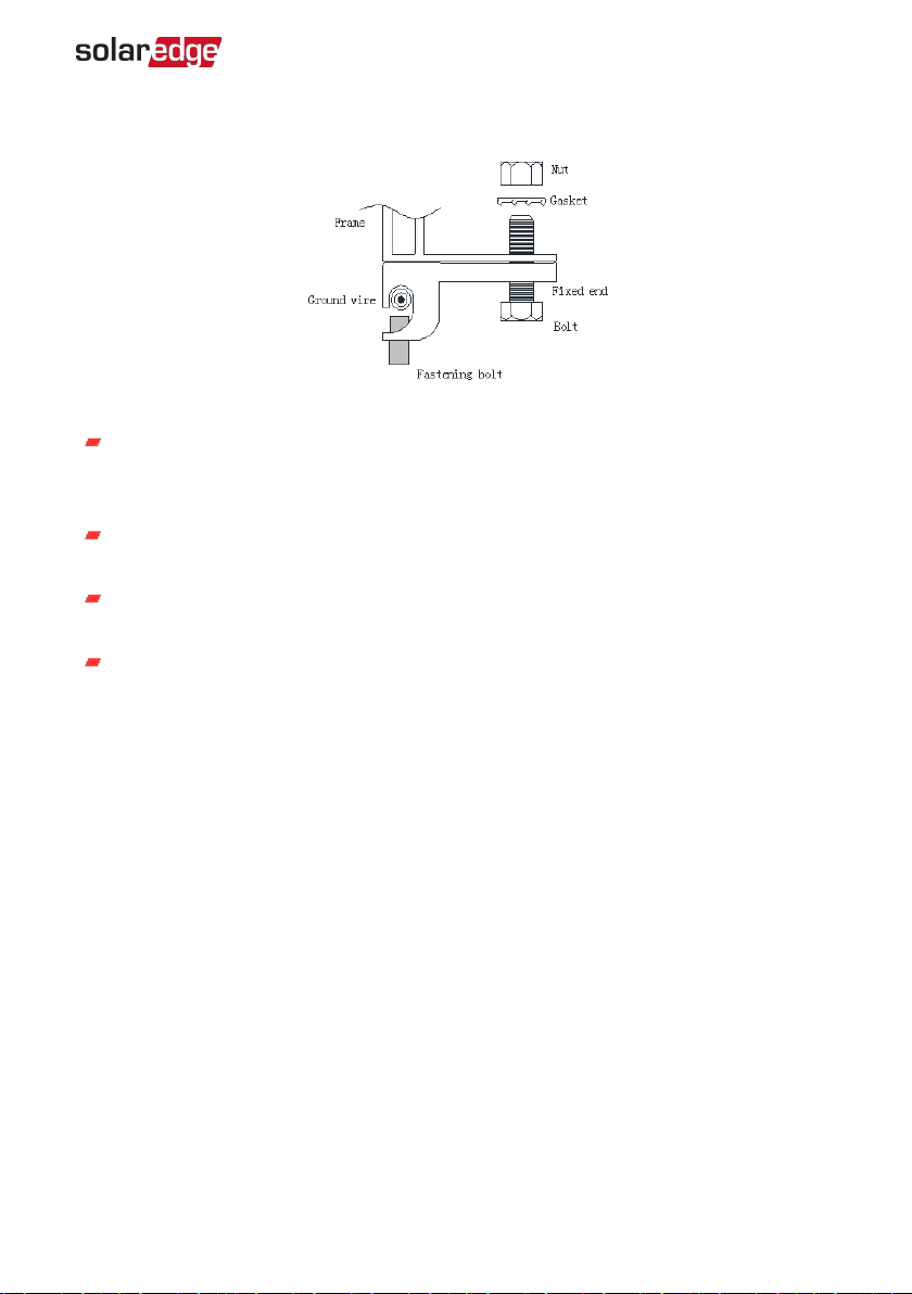
Grounding
Figure 10: Grounding the aluminum frame with a copper wire
Use the marked 5.5 mm grounding holes to ground the anodized aluminum frame.
Use an M5 nut, an M5 gasket, and an M5 bolt, fastening bolt and a ground wire.
All nuts, bolts, and gasket should be made of stainless steel. See
Figure 10
.
Secure the ground wire on fixed end through fastening bolt (note that the copper
wire cannot be attached directly to the aluminum).
Insert the bolt through the fixed end and then through the hole in the aluminum
frame.
Add the gasket and nut on the other side of the bolt and tighten to secure all parts.
The tightening torque should be 2.1±0.1 N*m.
Chapter 3: Electrical Installation 17
Smart
Modules
Installation
Guide
MAN-01-00520-1.3
Chapter 4: Reporting and Monitoring
Installation Data
The Monitoring Platform
The monitoring platform provides enhanced PV performance monitoring and yield
assurance through immediate fault detection and alerts at the module, string and
system level.
Using the platform, you can:
View the latest performance of specific components.
Find under-performing components, such as modules, by comparing their
performance to that of other components of the same type.
Pinpoint the location of alerted components using the physical layout.
The monitoring platform enables accessing site information, including up-to-date
information viewed in a physical or logical view:
Logical Layout: Shows a schematic tree-layout of the components in the system,
such as: inverters, strings, modules, meters and sensors, as well as their electrical
connectivity. This view enables you to see which modules are connected in each
string, which strings are connected to each inverter, and so on.
Physical Layout: Provides a bird's eye view of the actual placement of modules in
the site, and allows pinpoint issues to the exact location of each module on a
virtual site map.
18 Chapter
4:
Reporting
and
Monitoring
Installation
Data
If you do not report the mapping of the installed power optimizers, the monitoring
platform will show the logical layout indicating which power optimizers are connected
to which inverter, but will not show strings or the physical location of power optimizers.
The monitoring platform includes a built-in help system, that guides you
through the monitoring functionality.
For more information, refer to https://www.solaredge.com/products/pv-
monitoring#/.
Smart
Modules
Installation
Guide
MAN-01-00520-1.3
To display a physical layout, you need to map the locations of the installed modules or
power optimizers. To map the locations, use one of the methods described in the next
sections.
Designer
Designer recommends inverter and power optimizer selection per site size and enables
report generation. You can create a project in Designer and export the site design with
the string layout to the monitoring platform.
For more information, refer to
https://www.solaredge.com/products/installer-tools/designer#/.
Mapper Application
Use the Mapper smart phone application to create a virtual map of a PV
site for enhanced monitoring and easier maintenance using one of the
two scanning options:
Scan the smart module's 2D bar-code located on the front of the module
Scan the power optimizer 2D bar-code
The Mapper application is integrated with the monitoring platform and enables:
Simple on-site registration of new systems.
Creating, editing and verifying system physical layout.
Scanning and assigning the module and power optimizer serial numbers in the
system physical layout.
For detailed information, refer to the
Mapper
demo movies:
Scanning a smart panel using the SolarEdge Mapper App
Upon scanning the smart module or the power optimizer, the Mapper activates a
dedicated mapping process to ensure that the power optimizer inputs are assigned to
their module(s). You can approve each input assignment separately.
Smart
Modules
Installation
Guide
MAN-01-00520-1.3
Creating
Logical
and
Physical
Layout
using
Installation
Information 19
I
C
n
r
s
e
t
a
a
t
l
i
la
n
t
g
io
L
n
o
I
g
n
ic
fo
al
r
a
m
n
at
d
io
P
n
hysical Layout using
To display a logical layout after the inverter was installed, insert the inverter serial
number in the new site created in the monitoring platform. When the communication
between the inverter and the monitoring server is established, the logical layout is
displayed.
This manual suits for next models
5
Table of contents
Other SolarEdge Control Unit manuals


Popular Control Unit manuals by other brands

GatesAir
GatesAir Intraplex VF-25 Installation and operation manual

Mitsubishi Electric
Mitsubishi Electric A1SJ71AP23Q user manual

wattwatchers
wattwatchers FBC-HC Installation and operating instruction

Lucent
Lucent Stinger Guide

Festo
Festo HMPL-20 Series operating instructions

CYG
CYG PRS-7395 instruction manual


