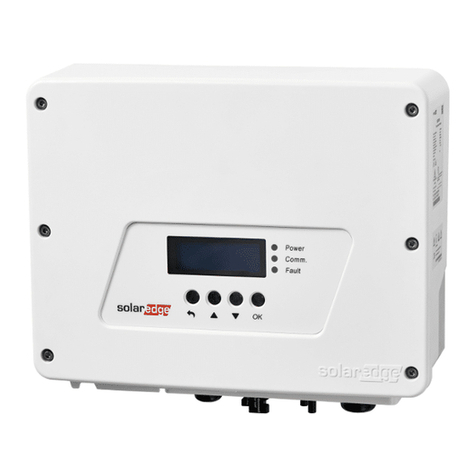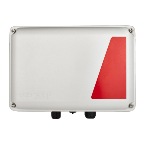
Comm
Enable
LED Indications
Configuring Installation
1. Run SetApp.
2. Scan the QR code on the inverter.
3. Follow the on-screen instructions.
4. Configure the import/export meter on SetApp.
SetApp
5
Power Control
Energy Manager
Backup
Configuration
Backup
Commissioning
Grid Backup
ON
On grid or boot
OFF
Backup mode
Blinking
Firmware upgrade
Fast blinking
Backup interface
received request
to identify itself
All LEDs OFF
No power
ON
Fault or boot
OFF
No faults
Blinking
Firmware upgrade
Fault
6Backup system checkup
Note: Before you start, make sure you have the Inverter system operating and producing with battery at above 20%.
Checking the backup operation may cause 2-3 seconds of electricity supply failure to the loads before they are powered up again; if
you have a load sensitive to such interruption, please disconnect it from the load backup section.
1. Make sure you have power from the grid and your inverter is working.
2. Before you start, check that the Battery SoC level is above 20%.
3. Make sure the Grid LED is ON and there is no fault detected. Turn OFF the main CB coming from the grid. Immediately after
that, all home loads should shut down and the On Grid LED should turn OFF.
4. Wait for a few seconds till all the home loads are powered up again, the LED marked as "Backup" should turn ON.
5. After a few minutes of stable operation, turn ON the main CB again.
6. “Backup” LED should turn OFF and the On Grid LED should turn on again.
ON
In backup or boot
OFF
On Grid
Blinking
Firmware upgrade
Fast blinking
Backup interface
received request
to identify itself
ON
Connected to the network/
received modbus packet/ boot
Blinking
There is no communication
over RF or RS485
•On RF –not connected
or temporarily
disconnected
•On RS485 –no packet
received for 30 seconds
Flickering
Bootloader is upgrading
software
Fast blinking
Device received a request to
identify itself
1
2
3
Connecting the Backup Interface
DANGER!
Before opening the covers and connecting the grid, please make sure that the main CB and the Inverters are OFF.
Note: If your local regulations require a short between Neutral and Protective earth on the load side (e. g. PE-N connection on the load side according to TNS, TT, and some TNC-S topologies), use the upper-right
terminal for the Load Neutral (see the figure below and the Main Connection Scheme). In case the topologies do not allow to generate the local PE-N (like in TNC-S, according to VDE 2510), please use this Neutral bus
to connect the load Neutral also.
1. Strip 120-150mm around the external grid cable and 8mm from the internal wire insulation. If needed, crimp the wire ferrules. Open the left gland marked with “Grid” and insert the grid cable.
Connect the ground wire first. Torque – 6Nm. Connect the wires Ground (yellow), Line (brown), and Neutral (blue) to their respective terminals.
2. Strip 120-150mm around the external load cable and 8mm from the internal wire insulation. If needed, crimp the wire ferrules. Open the right gland marked with “Load” and insert the load cable.
Connect the ground wire first. Torque – 6Nm. Connect the wires Ground (yellow), Line (brown), and Neutral (blue) to their respective terminals.
3. If your system doesn’t use Solaredge Home Network, connect the Backup Interface to your inverter using a CAT5 E or a CAT6. Open the communication gland and insert the communication cable,
close the gland. Pull out the communication connector and connect the communication cable wires to the G, A, B, and 12V +/-respectively. Use a twisted pair connection for A and B. Connect the
other side of this cable to the inverter.
4. Backup Interface includes a built-in meter. If you are using full home backup, you will have to disconnect any other external export/import meter and remove it from SetApp. The internal meter
must be configured as import/export. If you are using partial home backup, you will have to connect and define an external meter on the main panel and define it as the import/export meter of the
system.
For the Home Hub inverter
installation guide, scan
Cable
Outer diameter of 11-24mm
Cable cross-section of 6-25mm2
3
6 N*m
Neutral:
Short with
the Ground
(TT/TN-S)
1 2
Regular
Neutral
(TN-C-S)
3
6 N*m
Grid connection Load connection
TN-C-S
Load connection
TT/TN-S
6 N*m
Manually Switching to/from Grid-Connected
Mode
This section describes how to reconnect the grid
in case the Backup Interface hasn’t switched it
back for some reason.
Before operating these Bypass switches, make
sure the ON/OFF/P switch is in
ON
position.
If the ON/OFF/P switch is in
OFF
position, the
Bypass switch may malfunction.
Switching from
Off Grid
to
On Grid
In case the grid came back from outage, but the
system is still working in
Off Grid
, use the
following procedure to switch the grid back to
the system:
1. Remove the Backup Interface front cover
as shown above.
2. Press “Bypass On” on Manual Control
panel.
3. Close the external cover.
Please note that
Bypass OFF
disconnects the
grid from the home, use this switch ONLY in
case you want to check that the backup system
is ready for operation.
WARNING!
Only a certified installer is permitted
to perform this operation
ON
4 N*m
4Closing the Backup Interface
1.
2.
3.
Using M4 Allen key, secure Backup Interface internal lower cover
with two screws.
Using M5 Allen key, secure Backup Interface external front cover
with six screws.
Now you can turn on the main CB and the inverter.
4 N*m
ON
1
2
3
Before closing the Backup Interface, ensure proper operation:
Press “Bypass On”.
Press “Bypass Off”.
“Bypass On”“Bypass Off”1.
2.
To close the Backup Interface:
