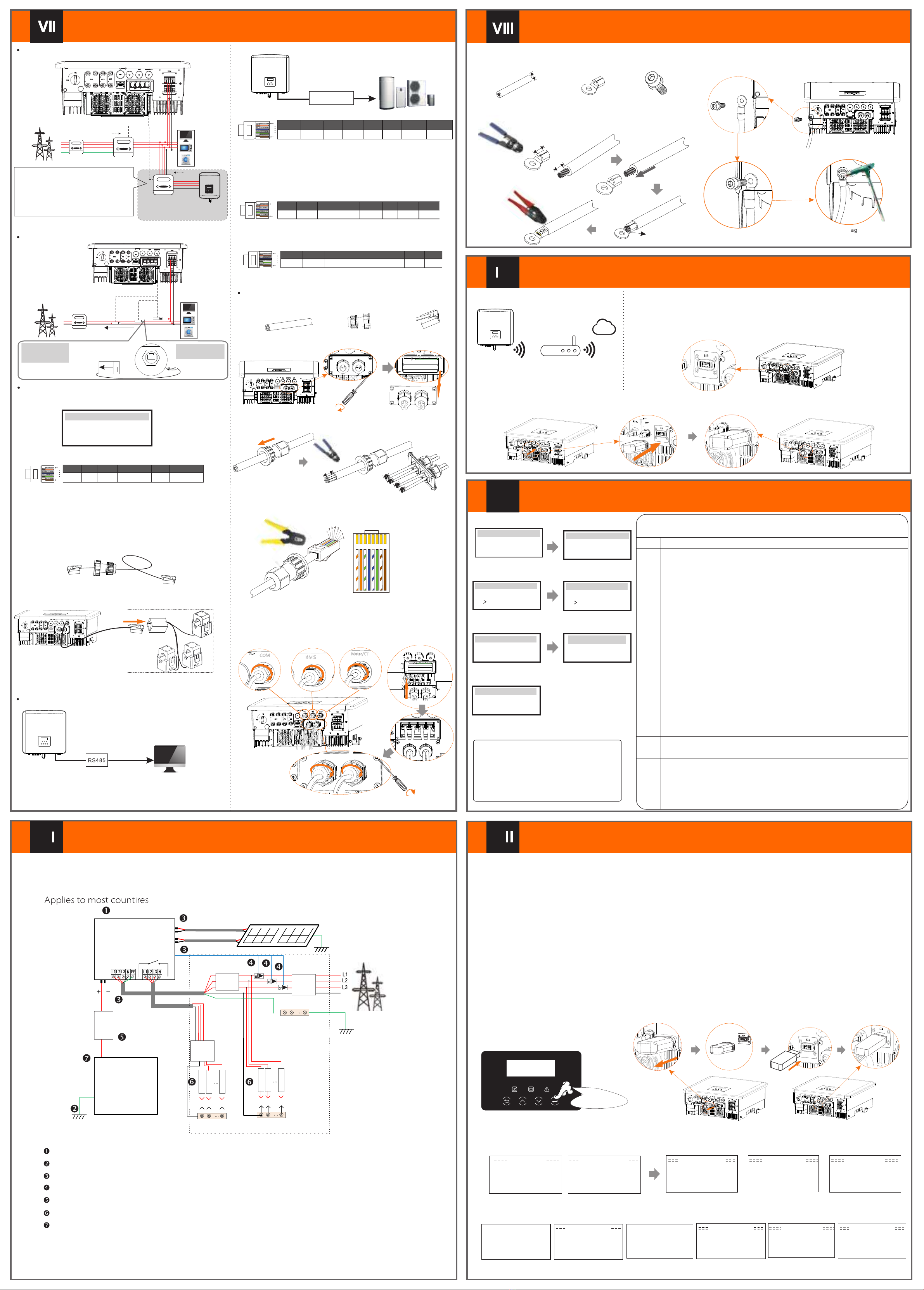
Communication Connection(BMS/Meter/CT/COM/DRM)Monitoring OperationFirmware Upgrading614.00898.00
Electric meter connection diagramCT connection diagramLCD settingsTo select CT, you need to enter Use setting, then enter CT/Meter Setting.
>Select CT
CT/Meter Setting
Step 1. Prepare a communication cable, and then find the communication adapter in the accessory bag.Step 3. Insert the communication cable through the communication adapter, and peel off the outer insulation layer of15mm.
15.00mm
Diagonal pliers12345678 Communication Connection StepsCOM CommunicationStep 5: Insert the communication line (CAN/DRM/OFF) into the corresponding port, lock the cover plate, and tighten the fastening head .Finally, the corresponding COM, METER, CT and BMS can be found to insert the corresponding ports of the inverter communication cable. And screw the communication adapter tightly.Start InverterØDONGLE connection diagram ØWireless monitoring accessories connection steps:Step 1. First find the DONGLE port of the inverter.Step 2. Plug Pocket WiFi into the DONGLE port.Start Guide
EnglishDeutschItalianLanguage2.Set language2021 ->11 <-1010:05Date time1.Set date time
CountryVDE0126Safety
3.Set the safety standard
CTMeterCT/Meter Setting
4.CT/Meter Setting
Export controlUse Value:10000W
Export Control
This function allows the inverter able to control energy exported to the grid. There are user value and factory value. The factory value is default which can not be charged by user. The user value set by installer must be less than the factory value.
5.Set export control*Functional ControlEnable DisableExternal ATS7.External ATS
-In order to upgrade the firmware smoothly, if the DSP and ARM firmware needs to be upgraded, please note that ARM firmware must be upgraded first, then DSP firmware!-Make sure that this directory is completely consistent with the above table, do not modify the firmware file name,Otherwise, the inverter may not work!-For the inverter, ensure that the PV input voltage is greater than180V (upgrade on sunny days). please ensure that the battery SOC is greater than 20% or the battery input voltage is greater than 180V. Otherwise, it may cause serious failure during the upgrade process!-If the ARM firmware upgrade fails or stops, please do not unplug the U disk and power off the inverter and restart it. Then repeat the upgrade steps.1) Please check the inverter version and prepare a U disk (USB 2.0/USB3.0) and personal computer before upgrading.2) Please contact our service support through service to obtain the firmware, and store the firmware in the U disk according to the following path. ØUpgrade preparation
Update: For ARM le: “update \ARM\618.00406.00_HYB_3P_ARM_V1.13_1220.usb”; For DSP le: “update\DSP\618.00405.00_HYB_3P_DSP_V1.14_1215.usb”;
Step 1. Please save the "Upate" firmware in your U disk first, and press the "Enter" button on the machine screen for 5 seconds to enter the shutdown mode. Then unscrew the waterproof cover, insert the U disk into the "upgrade" port at the bottom of the inverter.ØUpgrade stepsStep 2. Find the "Upgrade" port of the inverter, unplug the monitoring module (Pocket WiFi/ Pocket 4G/Pocket LAN) by hand, and insert the USB flash drive.Step 3. LCD operation, enter the upgrade interface "update", as shown below(a): Please press the up and down keys to select ARM, then press the bottom of the page to select "OK", press the enter key to enter the software version interface;Update ARM Cancel>OK>ARMDSPUpdate (ARM )
Update ( ARM)
>618.00406.00_HYB_3P_ARM_V1.13_1220.usb(c)>ARMDSP(e)Upgrading---------25%(d)(a)(b)Step 4. Please confirm the new firmware version again and select the firmware to upgrade. The upgrade takes about 20 seconds. (d) When it is completed, the LCD screen returns to the "Update" page.(k)Update(DSP)Upgrade Successful
Update(DSP)
connect---------Update DSP File >618.00405.00_HYB_3P_DSP_V1.14_1215.hex(g)Update Selection ARM>DSP( f)(h)
Update(DSP)
Upgrading---------25%Update(DSP)(i)(j)DSP Erasing---------
6.Set work mode*>Mode Select self useWork Mode
5*.Export Control
Update ARM FileUpdate( ARM)
DRM4/8+3.3VDRM0GNDGND
The DRM pin is defined as follows:
DRM1/5DRM2/6DRM3/712345678
18ØØMeter/ CT PIN is defined as follows:COM PIN DefinitionØ
Drycontact_A(in)
GND485A485B+13V12345678
18
BMS_CANLX12345678
18
BMS_485ABMS_485BBMS_CANH
The BMS pin is defined as follows:
XXX
ØLong press for 5 secondsGrounding Connection(manodatory)xStep 2. Strip the grounding cable insulation(length”L2), insert the stripped cable into the ring terminal, and then clamp it.
L1
4 mm²
C
L2=L1+3mm
Diagonal pliersLeaking cableCrimping ToolStep 1. Prepare a one-core cable (4 mm²), and then find the ground terminal in the accessories.Hexagon keysTorque: 0.8±0.2N·mStep 4. Find the ground connection port on the inverter, and lscrew the ground wire on the inverter with an M5 Allen key.Start inverterØAfter the inverter is checked, the inverter will take the following steps:Communication cableCommunication adapterMultifunction terminalcrimping tool (RJ45)1) White with orange stripes2) Orange3) White with green stripes4) Blue5) White with blue stripes
6) Green
7) White with brown stripes8) BrownTurn on the Load switch and EPS(Off-grid) switchTurn on thebattery switch.Make sure the battery is well connected.Make sure the CT are connected.Confirm that all DC lines and AC lines are connected.Make sure that the inverter is fixed on the wall.Long press Enter for 5 seconds to exit the shutdown mode. Mode is the mode when it is turned off for the first time; factory default: off mode)Ensure that all ground wires are grounded.One-core cable (4 mm²OT terminalHexagon socket screws
GridHousehold Meter(three-phase meter)LoadL1NOther power generation equipmentMeter1Meter2
If the user has other power generation equipment (such as inverter) at home and wants to monitor both, the inverter provides Meter2 communication function to monitor the power generation equipment.For more information, please contact us.
EPS
L2L3
Meter/CT port is at the bottom of the inverter.
Meter/CT
GridHousehold MeterLoadsL1NL2L3
18
12345678485A485BCT-S-2CT-R-2CT-R-1CT-T-2CT-T-1CT-S-1
Note: Only one of the Meter and CT connections can be selected. Meter cable goes to pin terminal 4 and 5; CT-R cable to PIN Terminal 1 and 8; CT-S cable to PIN Terminal 2 and 7; CT-T cable is connected to terminals 3 and 6.Date ReadGridEPSCAN CA N LCD DRM Step 2. Remove the cover plate on the inverter and make the communication line.
15.00mm
Step 4. Insert the prepared communication cables into the RJ45 terminalsin sequence , and then use network cable crimping pliers to press them tightly.CAN1 CAN2 DRM OFF CAN1 CAN2 DRM OFF CAN C AN DRM SH UT GridEPSCAN CAN LC D DRM GridEPSCAN CAN LC D DRM
NBATBatteryN-BAR for loadsN-BAR for EPS(Off-grid) loadsEPS(Off-grid) loadsLoadsInverterPV 1PV 2E-BARRCDBreakerGridBreakerGridEPS(Off-grid)Main Breaker/RCD
BreakerBreaker
CTDistribution BoxEPSTorque screwdriver (Torque: 1.2±0.1N·m)
There are 4 work modes for choice. Self use/ Back Up Mode/ Feed in Priority/ Force Time Use
All these work modes is available for on-grid condition only:
NameDescriptionEPS(Off-grid)Self Use
Backup
Feed-in
mode
priority
6*.Set work mode
The self-use mode is suitable for areas with low feed-in subsidies and high electricity prices.① When the power of PV is sufficient Active Charging or Discharge time period: PV will power the battery. When the battery is fully charged, PV will power the load, and then sell the surplus power to the grid.(The inverter will limit the output if Feed-in limit or zero feed-in is needed) (PV>Battery charge, PV →Battery→Load → Grid) ② When the power of PV is insufficient Active Charging time period: PV will power the battery and the remaining power will be taken from the grid when PV is not enough. PV and grid power will charge the battery until it reaches the set value. And then PV will power the load and the remaining power will be taken from the grid when PV is not enough. The battery will not discharge at this time.(PV<Battery charge, PV + Grid → Battery) Active Discharge time period: PV+BAT will power the loads together. If the power is still not enough, the remaining power will be taken from the grid. (PV<Load, PV + Battery + Grid → Load) ③ Without PV power Active Charging time period: The grid supplies the loads and also can charge the battery.(PV=0 ,Grid →Load + Battery)Active Discharge time period: The battery will power the home loads rstly. If the battery power is not enough ,the remaining power will be taken from the grid .The inverter will enter into the standby state.(PV=0 ,Battery+Grid→Load) Battery min SOC can be set:10%-100%;Charge battery to min SOC can be set:10%-100%.The Feed-in priority mode is suitable for areas with high feed-in subsidies, but has feed-in power limitation.①When the power of PV is sufficient Active Charging time period: PV power the battery to the set value, and then power the load, and sell the surplus power to the grid. If the local grid company limits the grid-connected power of the inverter, the excess energy continues to charge the battery. (PV>Battery, PV→Battery→Load→Grid → Battery) Active Discharge time period: PV will power the loads rstly, and surplus power will feed-in to the grid. (PV< Load, PV → Load → Grid )②When the power of PV is insufficient Active Charging time period:PV will power the battery and the remaining power will be taken from the grid when PV is not enough. PV and grid power will charge the battery until it reaches the set value. And then PV will power the load and the remaining power will be taken from the grid when PV is not enough. The battery will not discharge. (PV< Battery charge, PV + Grid → Battery) Discharge time period: PV+BAT will power the loads together. If the power is still not enough, the remaining power will be taken from the grid. (PV< Load, PV + Battery + Grid → Load)③Without PV power Active Charging time period :The grid will power the home loads and also charge the battery.(PV=0, Grid → Load + Battery) Active Discharge time period :The battery will power the home loads rstly. If the battery power is not enough, the remaining power will be taken from the grid. The inverter will enter into the standby state.(PV=0 , Battery+Grid → Load) Battery min SOC can be set:10%-100%; Charge battery to min SOC can be set: 30%-100%.The Back-up mode is suitable for areas with frequent power outages. Same working logic with “Self-use” mode. This mode will maintain the battery capacity at a relatively high level. (Users' setting) to ensure that the emergency loads can be used when the grid is off. Customers no need to worry about the battery capacity.Battery min SOC can be set:30%-100%; Charge battery to min SOC can be set: 30%-100%. The EPS(Off-grid) mode is used when the power grid is off. System will provides emergency power through PV and batteries to supply power to the household loads. (Battery is necessary )①When the power of PV is sufficientPV will power the loads rstly, and surplus power will charge to the battery. (PV> Load, PV → Load → Battery) ②When the power of PV is insufficientThe remaining power will be taken from the battery. (PV<Load, PV+battery → Load → Battery)③Without PV powerThe battery will power the emergency loads until the battery reached the min SOC, then the inverter will enter into the idle mode. (PV=0, Battery → Load)EPS(off-grid) SOC-min condition is adjustable within the range of 1 0%-25%;*The ground wire port of the M series inverter has been connected, and the D series needs to be wired according to the following steps.RJ45 terminals*11) To connect the Communication line of the CT line, the lines need to be made on both sides, connecting the RJ45 terminal on one side and the Communication line Adapter on the other.2) One side of the finished cable, Communication line adapter is inserted into the inverter, and one side of the RJ45 terminal is inserted into the CT connection.Distribution box Note: When installing, pay attention to water resistance. All the connected parts of CT must be put into the distribution cabinet.
Router
Cloud
Note: The RCD on the gure represents a leakage protection device with a circuit breaker function.COM
PENote: To connect the meter, please connect the GND terminal of the Meter1 to the ground.
COM
Drycontact_B(in)Drycontact_A(out)Drycontact_B(out)
Adapter BoxInverter communication control external equipment:x
(three-phase meter)in out out in
CAN1 CAN2 DRM OFF
Note: Customers can communicate or control the inverter and external devices through the COM interface. Professional users can use pins 4 and 5 to realize data acquisition and external control functions. The communication protocol is Modbus RTU. For details, please contact us. If the user wants to use the inverter dry contact to control external equipment (such as a heat pump), it can be used with our Adapter Box. For details, please refer to the Quick Installation Manual of the Adapter Box.Note: The communication port on the lithium battery must be consistent with thedefinition of pins 4, 5, 7, and 8 above;Note: Currently only PIN6 (DRM0) and PIN1 (DRM1/5) are functional, other PIN functions are under development.
Upgrade/DongleUpgrade/DongleUpgrade/Dongle
Please check the Pocket WiFi user manual/Pocket LAN user manual /4G user manual for more details.U Disk
xxUpgrade/Dongle
CT-SCT-TCT
Public Grid electricity
Note:The arrow on the CT must point at the public grid.CT-R
CT-RCT-SCT-Tthe direction of the CTs
Dongle/Upgrade
Upgrade/Dongle
/Upgrade
*DONGLE port connection line of the M series inverter is on the X3-Matebox,for specific installation details, please refer to the X3-Matebox Quick Installation Guide It is necessary to wire the D series according to the following steps.


