Solcon TPS User manual

Solcon Industries Ltd.
T
TP
PS
S
T
Th
hy
yr
ri
is
st
to
or
r
P
Po
ow
we
er
r
S
Sy
ys
st
te
em
m
8
8-
-1
15
50
00
0A
A,
,
2
23
30
0-
-1
10
00
00
0V
V
IInnssttrruuccttiioonn
MMaannuuaall
Ver. 22042019
www.solcon.com

2 • Table of content
________________________________________________________________________________________________
TPS Instruction Manual
1. TABLE OF CONTENT
1.Table of content....................................................................................................................... 2
2.Safety & Warnings................................................................................................................... 4
2.1Safety......................................................................................................................................... 4
2.2Attention..................................................................................................................................... 4
2.3Warnings.................................................................................................................................... 4
3.Technical Data ......................................................................................................................... 5
3.1Introduction ................................................................................................................................ 5
3.2Rating, Frames sizes and Weights ............................................................................................ 5
Refer to section 5 page 15 for detailed dimensional drawings ......................................................... 5
3.3TPS Selection ............................................................................................................................ 5
3.4Ordering Information .................................................................................................................. 6
3.5Mains and control description .................................................................................................... 7
3.6Input / Output indication............................................................................................................. 9
3.7Load Connections ...................................................................................................................... 9
3.8Modes of operation .................................................................................................................... 9
3.8.1Zero Crossing..................................................................................................................9
3.8.2Phase Control................................................................................................................10
3.8.3Phase control to zero crossing (Soft start) ....................................................................10
3.8.4Phase Control-Power ....................................................................................................10
3.9Synchronized mode ................................................................................................................. 11
4.Recommended Wiring Scheme............................................................................................ 12
4.1Load connection schemes ....................................................................................................... 12
4.2INSIDE DELTA Wiring ............................................................................................................. 13
4.3Typical control scheme ............................................................................................................ 13
4.4Communication and Synchronization wiring ............................................................................ 14
4.5Wiring Notes ............................................................................................................................ 14
4.5.1Short Circuit Protection .................................................................................................15
4.5.2Transient Protection ......................................................................................................15
5.Dimensions ............................................................................................................................ 15
5.1400-690VAC Models................................................................................................................ 15
5.21000VAC Models ..................................................................................................................... 19
6.Installation.............................................................................................................................. 20
6.1Prior to Installation ................................................................................................................... 20
6.2Mounting .................................................................................................................................. 20
6.3Temperature range & heat dissipation..................................................................................... 20
6.4Protection bus-bars covers for power terminals....................................................................... 20
6.5Jumpers settings for analogue input configuration .................................................................. 21
6.6Dip switches settings for analogue output optional PCB ......................................................... 21
7.Control Keypad...................................................................................................................... 23
7.1LCD Arrangement .................................................................................................................... 23
7.2Push-buttons............................................................................................................................ 23
7.3Status LEDs. ............................................................................................................................ 24
7.4Reviewing and modifying parameters...................................................................................... 24
7.5Special actions performed by the key-pad............................................................................... 24
7.5.1Run self test, Software version, default parameters and clear statistical data ..............24
7.6Mode Pages............................................................................................................................. 25
7.7Mode Pages, parameters & default values .............................................................................. 26
7.7.1Main parameters settings – page 1...............................................................................28
7.7.2I/O Parameters – page 2 ...............................................................................................30
7.7.3Protection Parameters – page 3....................................................................................32

3 • Table of content
________________________________________________________________________________________________
7.7.4Load sheding parameters settings– page 4 ..................................................................34
7.7.5Tripping/alarm prameters – page 5 ...............................................................................35
7.7.6Comm. Parameters – page 6 ........................................................................................36
7.7.7Actual data – page 7 .....................................................................................................37
7.7.8Statistical data – page 8................................................................................................38
7.7.9Fault data – page 9 ......................................................................................................38
8.TROUBLE SHOOTING........................................................................................................... 39
8.1Warranty Claim and Fault Report ............................................................................................ 41
To be completed By Solcon Service Dept. ................................................................................41
Return Material Authorization Number......................................................................................41
9.TECHNICAL SPECIFICATIONS............................................................................................. 42

4 • Safety & Warnings
________________________________________________________________________________________________
2. SAFETY & WARNINGS
2.1 Safety
1 Read this manual carefully before operating the equipment and follow its
instructions.
2 Installation, operation and maintenance should be in strict accordance
with this manual, national codes and good practice.
3 Installation or operation not performed in strict accordance with these
instructions will void manufacturer warranty.
4 Disconnect all power inputs before servicing the TPS and/or the load.
5 After installation, check and verify that no parts (bolts, washers, etc) have
fallen into the TPS.
2.2 Attention
1 This product was designed for compliance with IEC 947-4-3 for class A
equipment. TPS 1000V were also type tested to meet this standard.
2 Use of the product in domestic environments may cause radio
interference, in which case, the user may be required to employ
additional mitigation methods.
3 Utilization category is AC-51: 1,4 x Ie – 1 s, uninterrupted duty. For
further information, see Technical Specification
2.3 Warnings
1 Internal components and PCBs are at mains potential when the TPS is
connected to mains. This voltage is extremely dangerous and will cause
death or severe injury if contacted.
2 When TPS is connected to mains, even if control voltage is disconnected,
full voltage may appear on its output.
3 The TPS must be grounded to ensure correct operation, safety and to
prevent damage.
4 Check that Power Factor capacitors are not connected to the output side
of the soft TPS.
5 Do not interchange line and load connections
6 Phase Control Firing, may cause Radio interferences, in which case the
user may be required to employ additional mitigation methods.
The company reserves the right to make any improvements or modifications to its products without
prior notice.

5 • Technical Data
________________________________________________________________________________________________
3. TECHNICAL DATA
3.1 Introduction
Solcons’ Thyristor based Power System (TPS) is a heavy duty fully digital, Zero-crossing, Phase Control or
Phase Control-Power, three phase control power unit for all types of Resistive/Inductive loads (temperature
control of heaters, etc.).
Providing a wide range 8-1500A, 230-1000V, 50/60Hz, it can be installed in a variety of heating systems.
Control of output voltage can be done by input signal of 0-10VDC, 4-20mA, 0-20mA, by a potentiometer
(Optional) or via communication (Optional) for precision temperature control.
A special optional digital synchronization system enables load sharing and prevents excessive loading in multi
controller applications.
Fully programmable with 9 protection functions, including “Load Unbalance” alarm to detect a faulty element,
even in parallel connected element system and “Under power level” alarm to detect faulty element in case the
system is designed to work unbalanced.
Two line, 16 character LCD display is used for the TPS programming, actual values, statistical & maintenance
data.
Options:
- Potentiometer input for control. (Without the need for external power supply)
- Multi TPS synchronization system for load shedding
- RS-485 communication for TPS programming, remote data readings and controlling.
- Analogue output PCB (4-20mA, 0-20mA or 0-10V).
3.2 Rating, Frames sizes and Weights
Please note that the company reserves the right to
make any improvements or modifications to its
products without prior notice!
Refer to section 5 page 15 for detailed
dimensional drawings
3.3 TPS Selection
Select the TPS according to LOAD RATED CURRENT(FLA) - as indicated on its nameplate.
Note:
TPS withdrawn current by the load must not exceed TPS RATED CURRENT in each and every phase of the
TPS!
TPS
type
up to
690VAC
Rated
Current
[A]
Dimensions
WxHxD
[mm]
Weight
[Kg]
TPS 8 8 172x291x185 6.3
TPS 17 17 172x291x185 6.3
TPS 31 31 172x291x185 6.4
TPS 44 44 172x291x185 6.5
TPS 58 58 172x291x185 6.5
TPS 72 72 172x291x185 6.5
TPS 85 85 172x390x195 8.5
TPS 105 105 172x390x195 8.5
TPS 145 145 274x385x238 14.5
TPS 170 170 274x385x238 14.5
TPS 210 210 274x385x238 14.5
TPS 310 310 380x455x292 31
TPS 390 390 380x455x292 31
TPS 460 460 380x555x292 51
TPS 580 580 470x640x302 53
TPS 820 820 470x640x302 53
TPS 950 950 Consult factory
TPS 1100 1100 Consult factory
TPS 1500 1500 Consult factory
TPS
Model
1000VAC
Rated
Current
[A]
Dimensions
WxHxD
[mm]
Weight
[Kg]
TPS 55 55 280x550x346 33.5
TPS 105 105 280x550x346 33.5
TPS 160 160 280x550x346 33.5
TPS 200 200 280x550x346 33.5

6 • Technical Data
________________________________________________________________________________________________
3.4 Ordering Information
TPS 31- 400- 230- 230- 0- S
Full load
Current Mains
Voltage Control
Voltage Control
inputs
Voltage
Options Front Panel
Full load Current
Specify Description
TPS - Rated Current [A]
Models 400-690VAC
8, 17, 31, 44, 58, 72, 85, 105, 145, 170, 210, 310, 390, 460, 580, 820, 950, 1100,
1500
TPS - Rated Current [A]
Models 1000VAC
55, 105, 160, 200
Mains Voltage
Specify Description
400 230 – 400 VAC, +10% -15%, 50/60Hz
480 480 VAC, +10% -15%, 50/60Hz
600 600 VAC, +10% -15%, 50/60Hz
690 690 VAC, +10% -15%, 50/60Hz
1000 1000 VAC, +10% -15%, 50/60Hz
Control Voltage
Specify Description
115 115 VAC, 50/60Hz, +10% -15%
230 230 VAC, 50/60Hz, +10% -15%
110 VDC 110 VDC
(1)
, +10% -15%
24VDC 24 VDC
(1)
Notes:
(1) For DC control voltage or control inputs voltage - consult factory.
Options
Specify Description
0 No options
3M Communication RS-485 (MODBUS)
(1)
5 Analogue card
(1)
8 Harsh environment treatment
(1)
D Remote panel mounting replacing the original panel. (Supplied with 1.5 m cable).
(1)
,
(2)
Sync. Synchronization between up to 10 TPS units.
(1)
P Potentiometer control. (No need for external power source)
(1)
RU Russian display
Notes: For more than one option indicate, for example: 8+5 (Harsh environment and analogue
card)
(1) Must be ordered in factory – cannot be installed on site.
(2) D option is available for TPS 145A and up.
Front Panel
Specify Description
S Standard
Example:
TPS rated 820A, mains voltage - 230V, control voltage- 230VAC, control inputs- 48VDC Modbus
communication card, Harsh environment treatment, Synchronized TPS and standard front panel: TPS 820 -
230 – 230 - 48 - 3M+8+SYNC – S
Control inputs voltage
Specify Description
115 or 230 90 – 230 VAC, 50/60Hz or 90 – 230 VDC
24 24VAC, 50/60Hz or 24VDC
(1)
48 48VAC, 50/60Hz or 48VDC
(1)
Notes:
(1) For DC control voltage or control inputs voltage - consult factory.

7 • Technical Data
________________________________________________________________________________________________
3.5 Mains and control description
Indication Description Remarks
L1, L2, L3 Connection to mains voltage up to 690V.
Three Main Voltage levels are available:
400V (230-400V), 480V, 600V,690V and
1000V.
Note:
400V applies for 230 to 400V.
U, V, W Connection to resistive/inductive load. Load connection must be programmed to
TPS. Refer to section 3.7 page 9.
G Connection to Ground.
Terminal 1 Control phase (Positive – for DC control)
Three control voltages are available:
115VAC (50/60Hz), 230VAC (50/60Hz),
110VDC.
Terminal 3 Control Neutral (Return)
Terminal 4 Input – RUN command.
Terminal 5 Input - Auxiliary programmable input. Auxiliary Input can be programmed as one
of the options:
SYNC.
AUTHORIZED KEY
REMOTE RESET
N.C. EXT. FAULT
N.O. EXT. FAULT
N.C. INTERLOCK
N.O. INTERLOCK
Refer to section 7.7.2 page 30.
Terminal 6 Common. This terminal is a reference to terminals 4
& 5.
Terminal 7 Programmable output relay A –
Common.
Any of the output relays A, B or C can be
programmed to one of the following
functions:
Run, Alarm, Alarm fail safe, Trip, Trip fail
safe, Tripping/Alarm (Any fault
programmed in the tripping and alarm
options will energize the relay.)
Refer to section 7.7.2 page 30 for
programming output relays.
Terminal 8 Programmable output relay A –
Normally open (NO).
Terminal 9 Programmable output relay A –
Normally closed (NC).
Terminal 10 Programmable output relay B –
Common.
Terminal 11 Programmable output relay B –
Normally open (NO).
Terminal 12 Programmable output relay B –
Normally closed (NC).
Terminal 13 Programmable output relay C –
Common.
Terminal 14 Programmable output relay C –
Normally open (NO).
Terminal 15 Programmable output relay C –
Normally closed (NC).

8 • Technical Data
________________________________________________________________________________________________
Indication Description Remarks
Terminal 16 Analogue input signal (+) Terminals 16 & 17 are used for both, 0-
10V and 4-20mA, 0-20mA analogue
signals.
Terminals 16, 17 are used also when
potentiometer option is installed.
Refer to section 7.7.2 page 30 for
analogue input programming.
Notes:
Set internal jumper on the main control
board for the selected analogue input
signal. Refer to section 6.4 page 20.
When the TPS is programmed to get its
analog input via communication, these
inputs are not operative. Refer to section
7.7.6 page 36.
Caution
Damage may occur if jumpers are not
properly set (see instructions for JP1, JP2,
JP3 & JP4).
Jumpers are factory set for 4-20mA input.
Terminal 17 Analogue input signal (-)
Terminal 18 Synchronization signal (+) (Optional) Sync. signal use Shielded twisted pair, for
daisy chaining.
Up to 10 TPS units can be connected for
master slave configuration. Master Slave
configuration is designed for units located
in the vicinity of 20 meter maximum. Refer
to section 3.9 page 11.
Terminal 19 Synchronization signal (-) (Optional)
Terminal 20 POT. CW - Output voltage for potentiometer
connection (Only when option “P” is
present.) (Optional).
When option “P” is present connect
potentiometer CW to terminal 20,
potentiometer slide to terminal 16 and
potentiometer CCW to terminal 17.
For potentiometer input control refer to
section 6.4 page 20 for jumper settings
and program TPS input to “Voltage input
– Refer to section 7.7.2 page 30 for
analogue input programming.
Notes:
A potentiometer of 10kOhm must be used!
Use a high precision potentiometer for
better resolution.
When the TPS is programmed to get its
analog input via communication, these
inputs are not operative. Refer to section
7.7.6 page 36.
Terminal 21 Not connected
Terminal 22 Comm. Ground (Optional) Communication use Shielded twisted pair,
for daisy chaining.
Up 32 units can be connected for Modbus
RS485 communication.
For reliable communication, units should
be installed in the vicinity of 200m
maximum, from the first to the last unit.
Terminal 23 RS-485 Communication (-) (Optional)
Terminal 24 RS-485 Communication (+) (Optional)
(+) OUT Analogue output (+)(Optional) This output is used when analogue output
option is installed. Analogue output can be

9 • Technical Data
________________________________________________________________________________________________
Indication Description Remarks
(-) OUT Analogue output (-)(Optional) configured as 4-20mA, 0-20mA or 0-10V.
Refer to section 6.6 page 21 for hardware
settings. .
Analogue output can be programmed as a
signal proportional to output power or
average of 3 phase currents or I1 or I2 or
I3 or as a reflection of the analogue input
to the TPS.
Refer to section 7.7.2 page 30 for
programming analogue output.
3.6 Input / Output indication
3.7 Load Connections
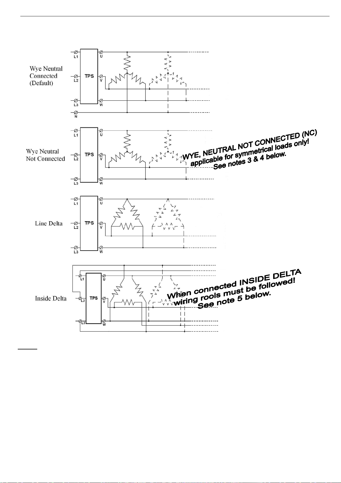
The TPS can be connect the load as shown in section 4.1 on page 12. The available configurations are:
Wye with Neutral Connected, Wye with Neutral not Connected, Delta or inside Delta.
Load connection type must be programmed to TPS. Refer to section 7.7.1 page 28.
Note:
Any number of parallel branches may be connected in the shown connection types provided that the total
connected load will not exceed the current rating of the TPS unit.
3.8 Modes of operation
3.8.1 Zero Crossing
In this mode of operation thyristor’s firing is performed so that current starts at its zero crossing point .
Main advantages of this mode are:
Minimizing RFI noise.
Minimizing current THD.Main disadvantages are:
No “Soft start”.
High inrush current in case of load with temperature dependant characteristic (lower resistance when
cold)
Current may vary in time.
In this mode of operation the TPS is programmed to operate in a cycle. (Tct)
When, during this cycle, analogue input is set to maximum – The TPS will conduct continuously.
When analogue input is lower, a proportional number of waves will be delivered to the load during Tct.
Firing method must be programmed to TPS. Refer to section 7.7.1 page 28.

10 • Technical Data
________________________________________________________________________________________________
Note:
Tct = 1-10Sec.
(Adjustable in 0.1 sec
steps)
Ton=2 cycles – Tct
Seconds (Minimum
conducting time is 2
cycles)
3.8.2 Phase Control
In this mode of operation thyristor’s firing is performed in every half cycle proportional to the analogue input.
Maximum analogue input will cause a full wave to load. When analogue input is lower, a proportional part of
the sine wave will be delivered to the load.
Main advantages of this mode are:
Enables “Soft start”
Current variations are limited.
Main disadvantages are:
Relatively high RFI noise.
Relatively high current THD.
Note:
When load is connected in WYE NEUTRAL NOT CONNECTED or in LINE DELTA (both connections are
without a neutral point) AND TPS is in PHASE CONTROL it is impossible to go to zero output.
Minimum possible firing for such case gives 10-20% of output voltage. This is since in this case the firing of
each phase depends on the three phases mains and we cannot control each phase voltage down to zero.
In this case, zero input in analogue input causes the minimum possible voltage to appear in the output. Then,
upon increasing the analogue input voltage, output voltage/current is monotonically increased.
Firing method must be programmed to TPS. Refer to section 7.7.1 page 28.
3.8.3 Phase control to zero crossing (Soft start)
The user can program a time of which the TPS will function in PHASE CONTROL and then change to ZERO
CROSSING mode.
This mode of operation allows soft starting of the load. This mode is recommended when load resistance has
a temperature dependant characteristic (lower resistance when cold).
Program PHASE CONTROL TO ZERO CROSSING time to a value from 1-3600 seconds.
During starting the TPS for the first 1-3600 seconds , TPS will operate in PHASE CONTROL mode of
operation thyristor’s firing is performed in every half cycle proportional to the analogue input.
The outcome of this process will be a small current withdraw from the supply and slow heating of the heat
element thus increasing its resistance and lowering the current.
Firing method must be programmed to TPS. Refer to section 7.7.1 page 28.
3.8.4 Phase Control-Power
In this mode of operation TPS function in PHASE CONTROL (See explanations above).
In PHASE CONTROL-POWER the output power of the TPS will be kept linear to the analogue input of the
TPS.
Firing method must be programmed to TPS. Refer to section 7.7.1 page 28.

11 • Technical Data
________________________________________________________________________________________________
3.9 Synchronized mode
This mode of operation is applicable only if mode of operation is set to ZERO CROSSING.
In this mode of operation the TPS Sync. Terminals should be wired in “daisy chain” as shown in section 4.4 on
page14. This mode is used to time share the ON time (Ton) period between the units.
In this mode, the beginning of the ON cycles of the connected TPSs is equally shifted.
For example:
No. of TPS units – 3
Cycle time when TPS is in ZERO CROSSING (Tct – see section 3.8.1 page 9) – 3 seconds.
In this example TPS#1 will be set to master and TPS#2, TPS#3 will be set to slave.
When system is stated, TPS#1 will go to ON first, TPS#2 will go to ON after 1 second (3 seconds/3), TPS#3
will go to ON after 2 seconds.
So, if the required duty cycle (Ton/Tct) is less than 1/3, one TPS only can be in ON state.
The Master is transmitting a “Sync” signal, received by all connected TPSs (Sync group members).
Only one unit of the group should be set as Master. All others should be set as slaves.
Refer to section 7.7.4 page 34 for programming.
Notes:
1. Sync. LED will lit once function is enabled.
2. In order to have a full number of ON cycles it is recommended to program the ON-OFF CYCLE
time In such manner that the number of cycles (50 or 60 Hz) divided by the number of connected TPS
units will be an integer . i.e. if 3 TPS units are connected with 50Hz mains, the ON-OFF time can be,
for example, 0.9Sec (45 cycles), 1,2 Sec (60 cycles), 3Sec (150 cycles).
3. Synchronized mode cannot be implemented if one current analog input is connected to several TPS
units in series.
12 • Recommended Wiring Scheme
________________________________________________________________________________________________
4. RECOMMENDED WIRING SCHEME
4.1 Load connection schemes
Notes: (1) – Set connection type to TPS. Refer to section 7.7.1 on page 28
(2) When load is connected in WYE NEUTRAL NOT CONNECTED or in LINE DELTA (both
connections are without a neutral point) AND TPS is in PHASE CONTROL it is impossible
to go to zero output.
Minimum possible firing for such case gives 10-20% of output voltage. This is since in this
case the firing of each phase depends on the three phases mains and we cannot control
each phase voltage down to zero.
In this case, zero input in analogue input causes the minimum possible voltage to appear
in the output. Then, upon increasing the analogue input voltage, output voltage/current is
monotonically increased.
(3) WYE, NEUTRAL NOT CONNECTED (NC) applicable for symmetrical loads only.
Connecting to non symmetrical loads might damage the load!
(4) When WYE, NEUTRAL NOT CONNECTED (NC) applies set the UNBALANCE protection
to the lowest practical value and trip the TPS upon UNBALANCE or else load will damage.
Refer to section 7.7.3 on page 32.
(5) Refer to section 4.2 next page for INSIDE DELTA wiring instructions.

13 • Recommended Wiring Scheme
________________________________________________________________________________________________
4.2 INSIDE DELTA Wiring
When the TPS is connected INSIDE DELTA wiring must be exactly as in the following diagram:
L1-U, L2-V, L3-W represent the three controlled TPS
phases.
R1, R2 R3 represent the load.
L1, L2, L3 are mains voltage.
Verify the following:
Phase sequence as below:
Phase L1-U of the TPS is connected between L1
and L3 of the mains.
Phase L2-V of the TPS is connected between L1
and L2 of the mains.
Phase L3-W of the TPS is connected between L2
and L3 of the mains.
4.3 Typical control scheme
Notes:
(1) - Use fuses for thyristors short circuit protection. Refer to section 4.5.1 on page 15
Note: In 1000V models semiconductor protection fuses for “type 2 coordination" are built –in.
(2) - For Aux. input programming refer to section 7.7.2 on page 30.
(3) - For programmable output relays A, B &C refer to section 7.7.2 on page 30.
(4) - When emergency Stop switch is required it is recommended to trip a series contactor or the
feeding circuit breaker. (Not shown)
(5) – Potentiometer control is only possible if option P (Potentiometer control) is ordered.
(6) – Only short current protection is mandatory in models other than 1000V. The TPS has a
built-in over current protection.
L2
L3
L1

14 • Recommended Wiring Scheme
________________________________________________________________________________________________
4.4 Communication and Synchronization wiring
Notes:
(1) – Use shielded twisted pair for Synchronization loop and for RS485 communication.
(2) – For communication cabling length of cables should not exceed 200m.
(3) - For Synchronization cabling length of cables should not exceed 20m.
(4) - Synchronized mode cannot be implemented if one current analogue input is connected
to several TPS units in series.
4.5 Wiring Notes
WARNINGS! When mains voltage is connected to the TPS, even if control voltage is
disconnected, full voltage may appear on the TPS load terminals.
Therefore, for isolation purposes, it is necessary to connect an isolating device
before the TPS.
Power factor correction capacitors must not be installed on TPS load side.
When required, install capacitors on TPS line side.
Laptop computer
RS-232
Thyristor Power System TPS Thyristor Power System TPS Thyristor Power System TPS
TPS 1 TPS 2 TPS 10
RS-485
TPS 1 TPS 2 TPS 32
Communication Loop
(up to 32 units)
Synchronization Loop
(up to 10 units)
23(-) 24(+) 23(-) 24(+) 23(-) 24(+)
18(+) 19(-) 18(+) 19(-) 18(+) 19(-)

15 • Dimensions
________________________________________________________________________________________________
4.5.1 Short Circuit Protection
For “type 2 coordination”, use fuses for semiconductor protection to protect the TPS from a short circuit.
Fuses for semiconductor protection give excellent results because they have low I²t values and high
interruption ratings.
Recommended fuse selection procedure:
(1) Fuse rated voltage: Choose minimum fuse rated voltage which is above the rated voltage of the
mains.
(2) Fuse rated current: Select a fuse which is 1.6 times the rated TPS current
(3) Fuse I²t: Verify that the I²t value of the fuse is less than or equal to the I²t value of the thyristor in the
TPS as shown in the table below.
(4) TPS Model Max. Thyristor I2t
[A2Sec] TPS Model Max. Thyristor
I2t [A2Sec]
TPS-8 5,000 TPS-390 200,000
TPS-17 5,000 TPS-460 700,000
TPS-31 5,000 TPS-580 700,000
TPS-44 5,000 TPS-820 700,000
TPS-58 12,000 TPS-950 Consult Factory
TPS-72 12,000 TPS-1100 Consult Factory
TPS-85 12,000 TPS-1500 Consult Factory
TPS-105 15,000 1000V Models Installed fuses (A2Sec)
TPS-145 60,000 TPS-55 1000V Bussmann 170M3243 (16000)
TPS-170 60,000 TPS-105 1000V Bussmann 170M3243 (16000)
TPS-210 140,000 TPS-160 1000V Bussmann 170M3245 (54500)
TPS-310 200,000 TPS-200 1000V Bussmann 170M3246 (115000)
Note: In 1000V models semiconductor protection fuses for “type 2 coordination" are built –in.
The fuses listed under “installed fuses” in the table above are recommended, however equivalent fuses from
other manufacturers can be used as well as long as their I2t values are equal or lower to the values mentioned
in parentheses.
4.5.2 Transient Protection
Line transient voltages can cause a malfunction of the TPS and damage to the thyristors. All TPS units
incorporate Metal Oxide Varistors (MOV) to protect from normal line voltage spikes.
When higher transients are expected, additional external protection should be used (consult factory).
5. DIMENSIONS
5.1 400-690VAC Models

16 • Dimensions
________________________________________________________________________________________________

17 • Dimensions
________________________________________________________________________________________________

18 • Dimensions
________________________________________________________________________________________________
For other models dimensions – consult factory.

19 • Dimensions
________________________________________________________________________________________________
5.2 1000VAC Models
Note: In 1000V models semiconductor protection fuses for “type 2 coordination" are built –in.

20 • Installation
________________________________________________________________________________________________
For other models dimensions – consult factory.
6. INSTALLATION
WARNING! Do not interchange line and load connections
6.1 Prior to Installation
Check that LOAD RATED CURRENT (FLA) is lower than, or equal, to the TPS RATED CURRENT.
Note:
TPS RATED CURRENT (FLC)≥LOAD RATED CURRENT In all 3 phases!!
Check that Mains and Control voltages are as indicated on the TPS side label.
Make sure TPS RATED CURRENT(FLC)≥LOAD
RATED CURRENT! (In all 3 phases)
Make sure Mains voltage is right!
Make sure Control voltage is right!
TPS label - example
6.2 Mounting
The TPS must be mounted vertically. Allow sufficient space (at least 100mm) above and below the TPS for
suitable airflow.
It is recommended to mount the TPS directly on the rear metal plate for better heat dissipation.
Note:
Do not mount the TPS directly on the rear metal plate in case a ventilation fan or ventilation opening is on the
back side of the TPS.
Do not mount the TPS near heat sources.
Surrounding air temperature in the cabinet should not exceed 50ºC
Protect the TPS from dust and corrosive atmospheres.
Note: For harsh environments, it is recommended to order the TPS with printed circuit board coating. Refer to
section Error! Reference source not found. on page Error! Bookmark not defined. for ordering
information.
6.3 Temperature range & heat dissipation
The TPS is rated to operate over a temperature range of -10ºC (14ºF) to + 50ºC (122ºF).
Relative non-condensed humidity inside the enclosure should not exceed 95%.
ATTENTION! Operating at surrounding air temp. (Inside the cabinet) higher than 50ºC may
cause damage to the TPS.
Heat Dissipation is:
1.3x3xI+FAN and TPS consumption rating
Where:
Iis the RMS current of the TPS.
FAN and TPS consumption rating - is shown on the technical specifications page 42.
So, for example, the maximum heat dissipation for a 210A TPS is: 1.3x3x210+64=883Watt.
6.4 Protection bus-bars covers for power terminals.
Protection bus-bars covers can be fitted with power terminals.
Consult factory for this option.
This manual suits for next models
22
Table of contents
Other Solcon Power Supply manuals


Popular Power Supply manuals by other brands


Edge-Core
Edge-Core RPS900W installation guide

TDK-Lambda
TDK-Lambda ELC12 Series instruction manual

Capetti Elettronica
Capetti Elettronica Winecap BOX-PPS user manual

moon
moon Evolution 820S owner's manual

Federal Signal Corporation
Federal Signal Corporation SelecTone PS250 Installation and maintenance instructions

American DJ
American DJ MidiPak User instructions