Solid Solicard 4000 User manual

SOLICARD 4000
Installation guide UK
Contents 1
IG554000931B.doc
Contents
Introduction _______________________________________________ 1
Terminology _______________________________________________ 2
Technical specification ______________________________________ 3
4000CE ___________________________________________________ 8
4014LC Loop card ____________________________________________ 11
6416RK Relay card____________________________________________ 12
Peripheral Equipment _________________________________________ 13
DAC-30 __________________________________________________ 14
Peripheral Equipment _________________________________________ 21
Installation of DAC-30 _________________________________________ 22
Card Reader ______________________________________________ 23
Peripheral Equipment _________________________________________ 25
Assembly ________________________________________________ 26
Card Reader _________________________________________________ 27
Doors_______________________________________________________ 28
Wiring ______________________________________________________ 29
Master reset and addressing_________________________________ 32
Master reset and running mode for 4000 _________________________ 32
Perform a master reset and addressing of DAC-30 _________________ 32
Addressing of Card reader 6355MLB
II
___________________________ 34
Check-list at start up _______________________________________ 35
At the door __________________________________________________ 36
Indications _______________________________________________ 37
Trouble shooting guide________________________________________ 38
Overviews ________________________________________________ 39
Wiring Diagrams___________________________________________ 51


SOLICARD 4000
Installation guide UK
1
Introduction
The purpose of this manual is to assist in the projecting and installation of
the access control system SOLICARD 4000. The manual is intended for
project managers or leaders, consultants, and installation technicians.
Readers of this manual should possess a basic knowledge of telecom
equipment.
To understand the different technical terms, we recommend you to read
through the chapter “Terminology”, found on the next page. The manual
contains the following drawings:
•Measure sketches
•Wiring Diagrams
•Terminal blocks
See table of contents.
We continuously develop and improve all our products including our
manuals and therefore appreciate feedback concerning this manual and
the system itself.
Phone, write, or send a fax or e-mail.
SOLID AB
Sjöviksbacken 24 pl.8
SE-117 43 Stockholm
Phone: +46 8 685 10 00
Fax: +46 8 685 10 20
E-mail: [email protected]
We make reservations for mistakes and future alterations in this manual.

SOLICARD 4000
Installation guide UK
2
Terminology
In the following text door, gate, etc. is called door.
The following abbreviations/expressions are used throughout the
document.
ABP = Alarm bypass
CU = Control unit
PC = Computer
Activities
All activities performed by the control unit are done in co-operation with the
4000 program. For deeper information we ask you to read that part of the
manual.
The main use for an access control system is to control and facilitate
movements in a predefined area or in a building. One group of people will
have access to all areas, other can have limited access to some parts.
It is important to establish card users and access levels before the
programming of the system is made.
SOLICARD 4000 can handle 1 to 16 doors and is delivered with an easy to
use program for Windows.
The system is built around a control unit where an intelligent DAC-30 is
installed at every door.

SOLICARD 4000
Installation guide UK
3
Technical specification
4000 Control unit
24V feeding KP-1:1&2 17-24V AC/DC
At 12V DC feeding KP-1:3&4 +12V = 3/0V = 4
Temperature range +5° – +40°C
Internal consumption See Table 1
below
The table below shows the current consumption in 4000 when
communicating with DAC-30 (not running DAC-30).
DAC-30 1 2 3 4 5 6 7 8
24V to
4000CU 160
mA 170
mA 180
mA 190
mA 220
mA 230
mA 240
mA 250
mA
9 10 11 12 13 14 15 16
270
mA 280
mA 290
mA 300
mA 320
mA 330
mA 340
mA 350
mA
DAC-30 1 2 3 4 5 6 7 8
12V to
4000CU 190
mA 205
mA 220
mA 235
mA 270
mA 285
mA 300
mA 315
mA
9 10 11 12 13 14 15 16
350
mA 365
mA 380
mA 395
mA 430
mA 445
mA 460
mA 475
mA
Table 1

SOLICARD 4000
Installation guide UK
4
DAC-30
24V feeding KP-1:1&2
17-24V AC/DC *
12V DC stabilized feeding KP-1:6&7 +12V = 6/0V = 7
Temperature range +5° to +40° C
DAC-30 current consumption 12V DC Max 130mA
24V DC Max 70mA
Current consumption relay card Approx. 30mA/relay
Relay current limitation 1A
Total 12V current consumption, i.e. electric strike,
reader and 12V regulated output Max 0,7A (700mA)
Buzzer KP-2:17&18 Max 100mA
* When using a 24V electrical lock the DAC-30 shall be fed with 24V.
The table below shows the current consumption for the DAC-30 fed with
24V and with 1 or 2 readers connected.
Locked
mode Unlocked
mode Of that illumina-
tion in reader
DAC-30 fed with 24V 70mA 100mA
1 pcs. 6355MLB
II
110mA 160mA 15-20mA
2 pcs. 6355MLB
II
150mA 200mA 30-40mA
Table 2
The table below shows the current consumption for the DAC-30 fed with
12V and with 1 or 2 readers connected.
Locked
mode Unlocked
mode Of that illumina-
tion in reader
DAC-30 fed with 12V 100mA 120mA
1 pcs. 6355MLB
II
160mA 200mA 15-20mA
2 pcs. 6355MLB
II
230mA 280mA 30-40mA
Table 3

SOLICARD 4000
Installation guide UK
The table below shows the DAC-30 fed with 24V and with a motor lock
connected.
At work Slowed down Normal mode/
Waiting mode
DAC-30
24V fed with
motor lock
Start
peak for
0,1 sec.
Remaining
operating
time
Run for 3 sec., pause
for 4 sec. repeated 5
times. After that run
for 1 sec., pause for 1
min.
Plus Table 6 x
the number of
readers
EL650 550mA 280mA 700mA 190mA
8164 700mA 330mA 750mA 190mA
8087S 1.100mA 330mA 1.200mA 140mA
8000S 450mA 180mA 500mA 140mA
Table 4
The table below shows the DAC-30 fed with 12V and with a motor lock
connected.
At work Slowed down Normal mode/
Waiting mode
DAC-30
12V fed with
motor lock
Start
peak for
0,1 sec.
Remaining
operating
time
Run for 3 sec., pause
for 4 sec. repeated 5
times. After that run
for 1 sec., pause for 1
min.
Plus Table 7
x the number
of readers
EL650 570mA 300mA 720mA 200mA
8164 720mA 350mA 770mA 200mA
8087S 1.400mA 350mA 1.500mA 150mA
8000S 600mA 200mA 650mA 150mA
Table 5
5

SOLICARD 4000
Installation guide UK
6
6355MLB
II
Card reader
Voltage in 12V (from DAC-30)
Temperature range -40°C to +85° C
The tables below shows the current consumption for the reader connected
to DAC-30.
Normal Max
6355MLB
II
connected to DAC-30 that is fed with 24V 40mA 70mA
Table 6
Normal Max
6355MLB
II
connected to DAC-30 that is fed with 12V 70mA 120mA
Table 7
4 doors
1 pieces 4000CU, including one 4014LC loop card
4 pieces DAC-30
4-8 pieces 6355MLB magnetic card reader or similar
4 pieces TKN1/TKN2 Exit buttons
4 pieces Electric Strike
4 pieces Motor lock
1 pieces 2450PS or more if the system requires so
PC or Portable programmer
16 doors
1 pieces 4000CU, including one 4014LC loop card
3 pieces 4014LC Loop card
16 pieces DAC-30
16-32 pieces 6355MLB magnetic card reader or similar
16 pieces TKN1/TKN2 Exit buttons
16 pieces Electric Strike
16 pieces Motor lock
2 pieces 2450PS or more if the system requires so
PC or Portable programmer
There is also a relay card, 4016, which can be used to control three outputs
connected to optional relays (one card per control unit) to be used together
with the software for as an example alarm control.

SOLICARD 4000
Installation guide UK
7
System configuration
In the basic design the system can handle up to 4 doors (inner and outer
reader) and is delivered complete with an easy to use Windows program
for the programming.
Se more in the User guide under the heading To the installation contractor
wireman.
Memory at power failure At least 48 hours
Number of cards 7000
Number of events 2000
Number of schedules 15 (x 2 periods)

SOLICARD 4000
Installation guide UK
8
4000CE
4000CE in its basic design contains; a CPU card (at the top) and a loop
card (below) mounted in an aluminium casing. The control unit can be
supplemented with a relay card that is mounted over the CPU card giving
free relay outputs. Validation of card and PIN-codes are made in the control
unit and approval for each door is sent to respective DAC-30. The control
unit is programmed with valid cards and a number of schedules etc.
The control unit should be mounted indoors in a warm and dry space
(+5°-+40°). Make sure that the control unit is easily accessible.
Be careful when you strip the cable, then point each conductor towards an
appropriate cable inlet and adjust the length so it will lay flat against the
bottom of the casing and then up towards the right or left side. I facilitate
service and give a more professional impression.
Use conduit and mechanical protection where so is needed.
To guarantee operation at power failure the control unit should be equipped
with its own power supply and battery backup.
This also applies on all DAC-30.
Suitable power supply is 2450PS.

SOLICARD 4000
Installation guide UK
Casing
The casing is made of aluminium with lock and 7 rubber inlets, where the
hole have a diameter of 3x15,2 mm, 2x18,6 mm and 2x22,5 mm.
The casing with the measure 404,5x218x98,5 mm can hold up to 4 loop
cards.
9

SOLICARD 4000
Installation guide UK
CPU card
Microprocessor with memory, real time clock and built in backup. All
information for the control of the system is stored here, including data from
card and schedule times.
Portable programmer connection and terminal block (KP-01) you find on
this card.
Terminal block description for CPU
10

SOLICARD 4000
Installation guide UK
4014LC Loop card
Connections to the DAC-30 for each door are made on this card (4 doors
per card). The power supply to the door details (DAC-30, electric strike
etc.) is connected to this card when they are not locally powered.
Terminal block description
The card is mounted in the 4000 control unit below the CPU card.
The communication between the card and DAC-30 is made via a 20mA
constant power loop. If the loop is interrupted all communication is lost with
the DAC-30.
Every card makes it possible to connect 4 DAC-30 further to the system,
i.e. 4 doors. (Max 16 doors totally.)
Installation of additional 4014LC Loop card
The loop card is mounted below the CPU card in the control unit. Use the
four enclosed screws and fasten the corners in the rail meant for this.
Connecting the associated flat cable between AS3 on the CPU card and
AS3 on the 4014LC loop card makes the connection to the CPU card.
11

SOLICARD 4000
Installation guide UK
6416RK Relay card
The relay card is mounted over the CPU card with enclosed screws. The
enclosed flat cable is connected between the relay card and J8 on the CPU
card (to the right on the card, above the terminal block).
There are four relays on the card. Three of them are software controlled,
the fourth is used to monitor the control unit.
Maximum current consumption is 150mA.
Input KP-1:11&12 is a programmable input.
12

SOLICARD 4000
Installation guide UK
13
Peripheral Equipment
For further information on these products we reefer to the product data
sheets for each product.
Signal Transducer CL-20
Comprises the interface between the RS232 computer output and the
current loop of SOLICARD 4000. The power supply comes from a separate
transformer.
Transformer ST60S
ST60S is a protective transformer (240/24V 2,5A) with a ring-core that has
thermal protection. It is a suitable power supply for all our access control
products.
Power supply unit 24V 2450PS
2450PS emergency power supply (240V/24V 5A) have two (2) outputs that
each is two-pole fused with 2.5A, plus and minus individually fused. The
unit is equipped with restorable fuses for overload protection and deep
discharge protection with an alarm relay.
Overvoltage protection Z-01/Z-02/Z-03
An excess voltage limiting device or so called lightning conductor is used to
protect the loop from damage in case of stroke of lightning.
Z-01 is for 12V and Z-02 is for 24V.
Z-01 is a transient protection for replacement in the overvoltage protectors
above.

SOLICARD 4000
Installation guide UK
DAC-30
DAC-30 is an intelligent unit where all the door connections are made, for
example reader, electric strike, exit button, door monitor contact, alarm etc.
14

SOLICARD 4000
Installation guide UK
Terminal block KP-1
Terminal block KP-2
15

SOLICARD 4000
Installation guide UK
16
Terminal block description DAC-30
Free/D-N (KP-1:8)
Day/Night function for motor lock. Linked to 0V = Day.
Works as a free input when motor lock not is connected.
All changes generate a log event.
Schedule controlled output (KP-1:10)
Active C- out, Max 100mA. Open collector output.
Exit button (KP-2:7&8)
Unlocked when closed to 0V. The door will lock even if the input remains
closed, “flank triggered”.
Door monitor contact (KP-2:9&10)
The door is presumed closed when SW (pin 9) is connected to 0V (pin 10),
and DIP6 = OFF.
DIP6 ON = Balanced input on SW (see sketch on page 17).
OK = 2,2 kΩ
When direct connected motor lock is connected the input works parallel with
the magnet in the lock.
Electric strike (KP-2:11&12) Coil.
For function and voltage see jumper links, page 20.
ABP (KP-2:13&14) Alarm ByPass
NO = Normal mode
Blocking input (KP-2:15&16, pre mounted link)
The purpose of this input is to prevent anyone entering an alarmed section.
When this input is broken the DAC-30 will be blocked. The DAC-30 will not
accept the exit button or valid cards.
The function depends on if it is an alarm interface or if it is a slave in an
alarm zone.
Slave = Blocks only it self.
Alarm interface = Blocks concerned doors in the zone.
Buzzer (KP-2:17&18)
This output can be used for connection of an
external buzzer. The buzzer sound when the
buzzer in the reader sounds (if buzzer is
activated in the program).
•Door open to long
•Door forced
•Motor lock problem

SOLICARD 4000
Installation guide UK
Terminal block Relay card DAC-30RC
There are four relays on the relay card DAC-30RC
Choose between NO & NC with the jumper links to the right on the relay
card.
The desired functions is set via the PC program, see further in the user
guide.
Following functions is a selection, others are specified in the part of the
manual that is describing the software.
•Time controlled output
•Buzzer
•Temporary ABP (Alarm bypass)
•Automatic door operator
•Door position
•Tamper
•Permanent ABP (Alarm bypass)
17

SOLICARD 4000
Installation guide UK
Terminal block Alarm Interface DAC-30AI
The option card is mounted on the place for the relay card.
This means that you have to choose if it should be a relay function or a
detector function since only one of the cards can be mounted.
The resistors shown on KP-4 are the ones that will be delivered with the
alarm unit.
Do also set the correct function in the program, see further in the part of the
manual describing the software.
18
Table of contents
Popular IP Access Controllers manuals by other brands
SAFECONTROL
SAFECONTROL Touch-79W-A6 installation guide
Security Brands
Security Brands Ascent 16-X2 quick start guide
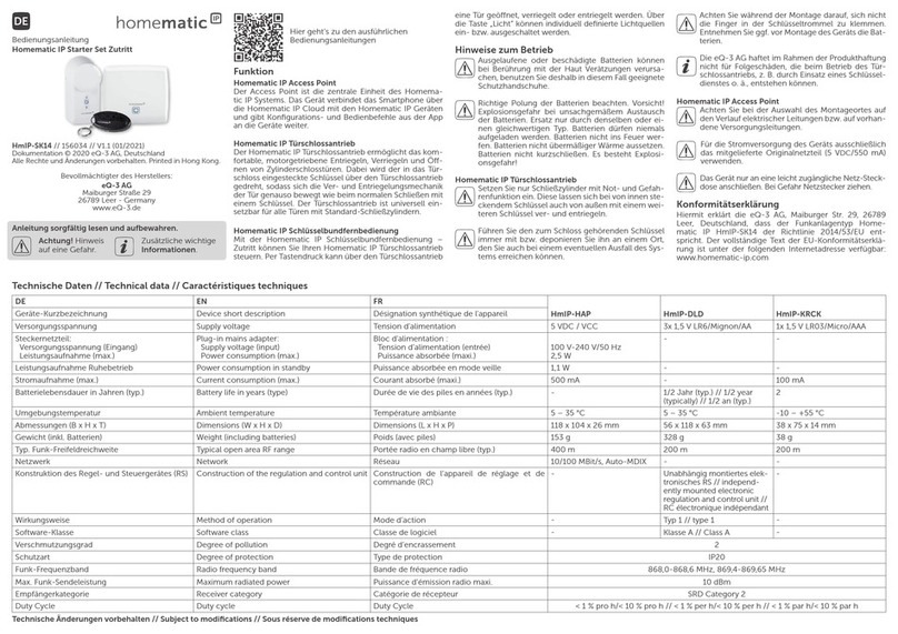
Homematic IP
Homematic IP HmIP-SK14 operating manual

Engineering Solutions
Engineering Solutions ACCESSOR 4000+ owner's manual
urmet domus
urmet domus 1099/811 quick guide
Toshiba
Toshiba e-Bridge ID Gate user manual
