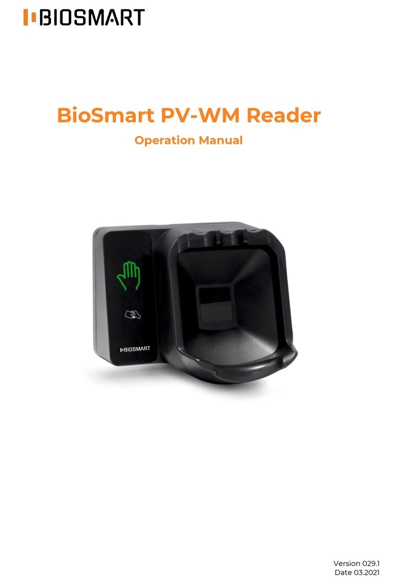
BioSmart BioSmart PalmJet User manual

Version 049.1
Date 03.2021
BioSmart BioSmart PalmJet,
BioSmart PalmJet BOX, BioSmart
PalmJet BOX-T Reader
Operation Manual

Operation Manual BioSmart BioSmart PalmJet, BioSmart PalmJet BOX,
BioSmart PalmJet BOX-T v.049.1|03.2021|en
Page 2 of 39
CONTENTS
Introduction .....................................................................................................................................................................................................................4
1The Reader Description................................................................................................................................................................................... 5
The Reader Purpose................................................................................................................................................................................... 5
Technical Characteristics........................................................................................................................................................................ 5
Composition and Appearance ............................................................................................................................................................6
Construction and Work ...........................................................................................................................................................................7
Marking and Sealing..................................................................................................................................................................................9
2Operating Restrictions...................................................................................................................................................................................10
Mechanical Factors...................................................................................................................................................................................10
Climatic Factors ..........................................................................................................................................................................................10
Biological Factors.......................................................................................................................................................................................10
Electromagnetic Fields and Electric Current ..........................................................................................................................10
Additional Restrictions ............................................................................................................................................................................ 11
3Installation ............................................................................................................................................................................................................. 12
BioSmart PlamJet Reader Installation......................................................................................................................................... 12
Installation of BioSmart PalmJet BOX reader (BioSmart PalmJet BOX-T) .......................................................... 13
4Reader Connection .......................................................................................................................................................................................... 15
Wire Assignment ....................................................................................................................................................................................... 15
Power Supply Connection ................................................................................................................................................................... 15
Ethernet Connection............................................................................................................................................................................... 15
Electromechanical Lock Connection............................................................................................................................................ 16
Buttons and Sensors to a Discrete Input Connection ....................................................................................................... 17
Load to Discrete Output Connection ........................................................................................................................................... 17
5Working Capacity Check.............................................................................................................................................................................. 19
6Network Settings..............................................................................................................................................................................................20
Network Features .....................................................................................................................................................................................20
IP CHANGER Utility.................................................................................................................................................................................. 20
7BioSmart SmartHub Software Service Installation ..................................................................................................................... 21
General Information................................................................................................................................................................................. 21
Installation Procedure ............................................................................................................................................................................ 21
8Biosmart-Studio Software Settings.......................................................................................................................................................23
General Instructions.................................................................................................................................................................................23
BioSmart SmartHub ................................................................................................................................................................................23
8.2.1 “General” Tab....................................................................................................................................................................................... 23
8.2.2 “System” Tab ..................................................................................................................................................................................24
8.2.3 “Diagnostics” Tab ........................................................................................................................................................................ 25
8.2.4 “Actions” Tab .................................................................................................................................................................................. 25
8.2.5 “Privilege” Tab ............................................................................................................................................................................... 26
Reader Settings.......................................................................................................................................................................................... 27
8.3.1 “General” Tab....................................................................................................................................................................................... 27
8.3.2 “System” Tab .................................................................................................................................................................................. 27
8.3.3 “Diagnostics” Tab ........................................................................................................................................................................29

Operation Manual BioSmart BioSmart PalmJet, BioSmart PalmJet BOX,
BioSmart PalmJet BOX-T v.049.1|03.2021|en
Page 3 of 39
9Reader Quick Start ........................................................................................................................................................................................... 31
10 Reader Faults and Methods of Its Elimination...............................................................................................................................33
11 Servicing..................................................................................................................................................................................................................35
General Information.................................................................................................................................................................................35
Protective Measures ................................................................................................................................................................................35
Maintenance for Intended Usage ...................................................................................................................................................35
Maintenance in Storage ........................................................................................................................................................................35
12 Storage and Transportation ...................................................................................................................................................................... 37
13 Utilization............................................................................................................................................................................................................... 37
Appendices.................................................................................................................................................................................................................... 38

Page 4 of 39
Dear Customers!
Thank you for purchasing our product. Subject to the rules of installation and operation, this device
will serve for many years.
Introduction
This operating manual (OM) applies to the BioSmart PalmJet, BioSmart PalmJet BOX, BioSmart
PalmJet BOX-T readers (hereinafter referred to as “readers”), the procedure for installation, connection, use
and configuration.
Documentation and software are constantly being improved, the latest current versions and software
may be found at https://biosmart-tech.com/.
Abbreviations used:
Software –software;
ACS –access control and management system;
OS –an operating system.
Before installation, configuration and operation of the reader, read the requirements of this manual
-this is example of important information that should be paid attention to.
Security Measures
It is forbidden to carry out installation, commissioning of the product during a thunderstorm, due to
the danger of electric shock during lightning discharges from interference on the communication line.
Requirements for the Personnel Qualifications
Employees who have studied this manual are allowed to install, connect and configure the reader.

Operation Manual BioSmart BioSmart PalmJet, BioSmart PalmJet BOX,
BioSmart PalmJet BOX-T v.049.1|03.2021|en
Page 5 of 39
1The Reader Description
The Reader Purpose
The readers are used as part of the BioSmart access control system together with the BioSmart
UniPass Pro controller or in conjunction with the BioSmart SmartHub software service.
Readers are designed for contactless reading of biometric data (palm vein pattern) of a person and
RFID-tag codes with subsequent transfer of the read information to the BioSmart UniPass Pro controller or
to a computer with BioSmart SmartHub installed.
BioSmart PalmJet reader is designed to build into a wall or turnstile. It’s located into a hole with
72 mm diameter and 45 mm depth.
BioSmart PalmJet BOX reader is designed for surface mounting using a special plate included in the
delivery set.
BioSmart PalmJet BOX-T reader is designed for surface mounting using a special plate included in
the delivery set. BioSmart PalmJet BOX-T reader is equipped with a built-in sensor for measuring body
temperature in the wrist area.
Technical Characteristics
Readers are compatible with the following RFID card formats:
NFC
MIFARE Classic
MIFARE Classic Mini
MIFARE Ultralight
MIFARE Ultralight C
MIFARE Ultralight EV1
MIFARE Plus S
MIFARE Plus SE
MIFARE Plus X
MIFARE Plus EV1
MIFARE DESFire EV1
MIFARE DESFire EV2
The main reader technical characteristics are shown in Table 1.
Table 1 - The reader main technical characteristics
Parameter
Value
BioSmart
PalmJet
BioSmart
PalmJet
BOX
BioSmart
PalmJet
BOX-T
Biometric ID
Palm vein pattern
Palm vein scanner type
Optical infrared
Palm distance from scanner, mm
From 30 to 90
Built-in RFID-tag reader
Yes
False Acceptance Rate based on biometric data, FAR *
10−8
Built-in temperature sensor
No
No
Yes
Temperature measurement accuracy
-
-
± 0,3 °С
Installation option
Rabbeted
installatio
n
Surface
mounting
Surface
mounting
Connection interface
Ethernet
(IEEE 802.3, 100BASE-TX)
Indicators
Buzzer and RGB LED
Number of the on-board relays
1
Electrical parameters of the on-board relay
DC 12 V 0,75 A

Operation Manual BioSmart BioSmart PalmJet, BioSmart PalmJet BOX,
BioSmart PalmJet BOX-T v.049.1|03.2021|en
Page 6 of 39
Parameter
Value
BioSmart
PalmJet
BioSmart
PalmJet
BOX
BioSmart
PalmJet
BOX-T
Relay contact status
Normal open
Number of discrete inputs/outputs
1/1
Discrete input signal level, V
From 5 to 12
Discrete output signal level, V
To 12
Maximum switching current of discrete outputs, mA
50
Discrete output type
Open collector
DC supply voltage, V
12 ±10%
Maximum consumed current, A
1
Case material
Plastic
Dimensions, mm
96х96х60
113х140х80
113х140х80
Net weight, g
350
550
550
Air temperature during operation, С
From –40
to + 35
From –40
to + 35
From +15
to +35
The upper value of the relative air humidity at a temperature
of 25 С, %
70
Enclosure protection
IP65
IP20
IP20
*The FAR value corresponds to the value FRR = 3%, obtained by calculation. The results correspond to a
database of 7,250 people.
Composition and Appearance
The reader appearance depends on its model.
BioSmart PalmJet reader has a built-in design and is shown in Figure 1.
Figure 1 –BioSmart PalmJet reader
BioSmart PalmJet BOX (BioSmart PalmJet BOX-T) reader is designed for surface mounting. The
appearance is shown in Figure 2.

Operation Manual BioSmart BioSmart PalmJet, BioSmart PalmJet BOX,
BioSmart PalmJet BOX-T v.049.1|03.2021|en
Page 7 of 39
Figure 2 –BioSmart PalmJet BOX reader
BioSmart PalmJet BOX-T reader is equipped with a built-in sensor for measuring body temperature
in the wrist area and is shown in Figure 3.
Figure 3 –BioSmart PalmJet BOX-T reader
1. Light indicator of operating modes
2. Palm vein scanner
3. Field for reading RFID-cards
4. Temperature measuring sensor (only for BioSmart PalmJet BOX-T)
Construction and Work
The reader works under the BioSmart SmartHub software service control or under the BioSmart
UniPass Pro controller control.
The reader, powered and connected to the BioSmart SmartHub software service or the BioSmart
UniPass Pro controller, enters into palm/card standby mode, according to the set operating mode.
When an object is brought to the palm vein biometric scanner, this object parameters are analyzed.
If the attached object is recognized as the palm of a living person, and biometric data of sufficient quality
may be read from the palm, then the biometric data is scanned in the infrared range. The read biometric
data is transferred to the BioSmart UniPass Pro controller or to a computer with the BioSmart SmartHub
software service. Next, the obtained biometric data is compared with the palm vein patterns stored in the
database. If a template was found in the database, deviations from which fall within the specified limit, the
1
2
3
4

Operation Manual BioSmart BioSmart PalmJet, BioSmart PalmJet BOX,
BioSmart PalmJet BOX-T v.049.1|03.2021|en
Page 8 of 39
access settings prescribe to grant access to the appropriate employee, then BioSmart UniPass Pro or
BioSmart SmartHub performs the actions specified in the working model for this situation and sends a
message about successful identification to the reader. If the template isn’t found in the database or the
access settings prescribe to deny access, then other actions are performed, prescribed by the operating
mode. A failed authentication message is being sent. Then there is a return to cyclic polling of the reader’s
state.
If the object attached to the reader is recognized as an RFID-tag (card), then the reader reads the
RFID-tag code and transmits it to the BioSmart UniPass Pro controller or to a computer with the BioSmart
SmartHub software service, where the RFID-tag code is compared with the codes stored in database. If a
match is found and the access settings instruct the corresponding employee to be allowed access, then
BioSmart UniPass Pro or BioSmart SmartHub performs the actions specified in the working model for this
situation. For example, BioSmart UniPass Pro or BioSmart SmartHub activates the relay and controls the
indication on the reader. If no match is found or the access settings prescribe to deny passage, then BioSmart
UniPass Pro or BioSmart SmartHub performs other actions specified in the working model. For example,
BioSmart UniPass Pro or BioSmart SmartHub controls the sound signal on the reader.
BioSmart PalmJet BOX-T reader has a built-in temperature sensor that works only with operating
modes with palm. According to the mode, after successful palm identification, the process of measuring the
wrist temperature starts. After measuring the temperature, the measured value is transferred to the
BioSmart UniPass Pro controller or to a computer with the BioSmart SmartHub software service. Depending
on whether the measured value is within the specified range (see par. 8.3.2), it is determined whether to allow
access to an employee or not. In this case, the corresponding sound and light indication will be triggered.
Detailed information about operating modes is given in paragraph 8.3.2.
The LED indicator along the case perimeter displays the current reader status (see Table 2).
The table of the reader sound and light signals is below, in the default setting.
Table 2 - The operating mode indication, LED indication
Action
Red
Green
Blue
Sound signal
(beeper)
General
BioSmart SmartHub with
PalmJet are connected
10 * 10 ms
A palm template from a
BioSmart PalmJet image is
received
1 * 10 ms
Image is captured from
BioSmart PalmJet
20 * 100 ms
1 * 2000 ms
1 * 30 ms
Cancel action
2 * 500 ms
2 * 500 ms
Identification
Successful identification
1 * 1500 ms
7 * 100 ms
1 * 300 ms
Failed identification
1 * 1500 ms
2 * 100 ms
Waiting for a second
identifier in multifactor
identification
20 * 250 ms
20 * 250 ms
Wrong palm position
1 * 30000 ms

Operation Manual BioSmart BioSmart PalmJet, BioSmart PalmJet BOX,
BioSmart PalmJet BOX-T v.049.1|03.2021|en
Page 9 of 39
Temperature
Temperature is
successfully measured
20 * 100 ms
1 * 2000 ms
1 * 60 ms
Temperature is higher or
lower the limit
20 * 20 ms
20 * 20 ms
The parameters of the indication operation mode is explained by example of the action "An image is
received from BioSmart PalmJet". The above settings mean the following:
Green signal 20 * 100 ms –the 20 times signal repetition with a duration of 100 ms;
Blue signal 1 * 2000 ms –the 1 time signal repetition with a duration of 2000 ms;
Sound signal 1 * 30 ms –the 1 time signal repetition with a duration of 30 ms.
Marking and Sealing
The serial number label is located on the back of reader case.
Each reader wire is labeled with a wire assignment (Table 4).
The packaging is marked with transport markings containing handling signs:
Crushable. Caution
Protect from moisture
Stacking limit 5 kg

Operation Manual BioSmart BioSmart PalmJet, BioSmart PalmJet BOX,
BioSmart PalmJet BOX-T v.049.1|03.2021|en
Page 10 of 39
2Operating Restrictions
This section contains requirements, non-observance of which is unacceptable for safety reasons and
which may lead to product failure or deterioration of its technical characteristics.
Mechanical Factors
Mechanical influences (shocks, vibrations) leading to the product structure damage must be
excluded. It's allowed to install the product directly on building structures (for example, on
walls, ceilings, foundations, floors, columns, farms) of enterprises, sales areas, etc. in places with
an insignificant shock level (an example of a minor shock is close-located slamming doors);
Mechanical influences leading to the product case damage, due to which liquid, dust, insects,
and foreign objects may get inside the case, are not allowed;
Mechanical influence damaging the biometric scanner surface (for example, scratches and
chips) are not allowed.
Climatic Factors
The product is allowed to operate at the ambient temperature and relative humidity specified
in the technical specifications;
It’s not allowed to operate the product when exposed to direct sunlight or light from nearby
bright light sources to avoid overheating of the product or deterioration of the quality of
scanning biometric data (due to optical interference);
The product operation in the immediate vicinity of flame sources is not allowed;
BioSmart PalmJet BOX and BioSmart PalmJet BOX-T readers operation when exposed to
atmospheric precipitation or other liquids is not allowed. The cases of these readers (in contrast
to the BioSmart PalmJet reader) are not protected against dust and moisture penetration into
the case, which may lead to the readers failure;
BioSmart PalmJet reader is protected from dust and moisture penetration into the case,
however, the biometric scanner surface must be protected from atmospheric precipitation
(hail, rain, snow), as well as frost, rime and ice. If hail falls on the biometric scanner surface, it
may be damaged. Rain, snow, ice, frost and rime falling on the biometric scanner surface (or
formed on its surface) may lead to the light signal distortion and deterioration of the biometric
data scanning quality;
BioSmart PalmJet reader is allowed to be operated in conditions corresponding to the
protection degree of the IP65 enclosure, while ensuring the case integrity, no damage (holes,
chips, cracks) through which liquid and dust can enter the case. It should be remembered only
the product case is protected from the liquids penetration, while the wires and connectors
used for connection are located outside the case and must be protected from the liquids
effects.
Example of permissible influences on the case in terms of IP65 protection degree: dust, splashes, rain,
water jets. Unacceptable influences are hot water jets under high pressure, immersion in water;
It’s not allowed to operate the product in environments with corrosive agents, in conditions of
sea (salt) fog;
The product operation in conditions of high concentration of static or dynamic dust (sand) is
not allowed. A dust (sand) layer accumulating on the biometric scanner surface can distort the
light signal and degrade the biometric data scanning quality. Sand particles can abrasively
affect the biometric scanner surface, which will also result in poor scan quality. BioSmart
PalmJet BOX and BioSmart PalmJet BOX-T readers (unlike the BioSmart PalmJet reader) are
not protected from dust (sand) getting inside the case, which may lead to failure of these
readers.
Biological Factors
The product operation under the moldy fungi influence, insects, and animals is not allowed.
Electromagnetic Fields and Electric Current
The product must be operated at the power supply voltage specified in the technical
specifications;

Operation Manual BioSmart BioSmart PalmJet, BioSmart PalmJet BOX,
BioSmart PalmJet BOX-T v.049.1|03.2021|en
Page 11 of 39
To minimize the negative impact on the built-in RFID-reader operation, don’t install the device
at a distance of less than 80 cm from other RFID-readers or other electromagnetic interference
sources.
Additional Restrictions
During the product operation, lightning protection of conection and power supply must be
provided;
It’s not allowed to operate the product in conditions of ionizing (radiation) exposure;
It’s not allowed to operate the product in explosive rooms or other places where the discharges
occurrence of static electricity or sparks may become an ignition source;
Unqualified interference in the product design by unauthorized persons is not allowed;
After the product has been in conditions of low temperature or high humidity, it must be taken
out of the packaging and kept in a dry room at a temperature of 20 ± 5 °С for at least 30 minutes
before turning on;
When using the built-in temperature sensor of the BioSmart PalmJet BOX-T reader and to
minimize the temperature measurement error, it’s necessary to exclude the cold air flows
influence (for example, from outside or an air conditioner) or hot air flows to the reader, as well
as the influence of various heaters and hot appliances.
The environmental requirements given in this instruction manual take into account typical factors
affecting product performance. At the operating facility, factors may exist or arise during operation that can’t
be predicted, estimated or verified, and which the manufacturer couldn’t take into account when
developing. In case of such factors manifestation, it’s necessary to agree on the admissibility of the product
operation under the manifested factors influence or to find another place for operation where these factors
are absent or don’t affect the product operation.

Operation Manual BioSmart BioSmart PalmJet, BioSmart PalmJet BOX,
BioSmart PalmJet BOX-T v.049.1|03.2021|en
Page 12 of 39
3Installation
The section contains the readers installation procedure and hardware kit. The mounting method for
BioSmart PalmJet and BioSmart PalmJet BOX (BioSmart PalmJet BOX-T) readers is different. Section 3.1
describes the installation procedure the BioSmart PalmJet reader, section 3.2 describes the installation
procedure the BioSmart PalmJet BOX (BioSmart PalmJet BOX-T) reader.
The readers must be installed with the power supply disconnected.
BioSmart PlamJet Reader Installation
The BioSmart PalmJet hardware kit includes the following items:
Self-Threaded Screw 3.5 x 38 - 4 pcs.
Butt Dowel 6 x 35 - 4 pcs.
Screw M3 x 12 - 2 pcs.
Figure 4 shows a diagram of the BioSmart PalmJet reader installation.
BioSmart PalmJet reader installation procedure:
1. Appreciate the best method to run the cable routing to connect the reader.
2. Prepare a hole in the surface, 72 mm in diameter and at least 45 mm deep, into which the
reader will be installed. Provide additional cable management space at the back of the reader.
If necessary, increase the hole depth for installing the reader, make channels for the cables in
the right direction.
3. Install the hold (1) so that the holes in the inner tabs are on the sides, on the left and right sides
of the prepared hole center.
4. Fix the hold (1) with dowels and self-threaded screws (2).
5. Insert the reader (3) into the hole through the hold (1).
The device orientation is important for further use and is related to the palm position during
scanning. The reader should be installed so that when the palm veins scanning the inscription
"UP" on the reader is at the top. If the reader is installed on a horizontal surface, then the
inscription "UP" should be located in the direction of user’s movement through this passage
point.
6. Mount the reader (3) to the hold with two screws (4).
7. Place the front panel (5) on the reader (3) over the installed device, in accordance with the
indicator lights position and fix with latches.

Operation Manual BioSmart BioSmart PalmJet, BioSmart PalmJet BOX,
BioSmart PalmJet BOX-T v.049.1|03.2021|en
Page 13 of 39
Figure 4 –BioSmart PalmJet reader installation scheme
Installation of BioSmart PalmJet BOX reader (BioSmart PalmJet BOX-T)
The BioSmart PalmJet hardware kit includes the following items:
Self-Threaded Screw 3.5 x 38 - 4 pcs.
Butt Dowel 6 x 35 - 4 pcs.
Readers are supplied with a mounting plate for vertical or horizontal surfaces, depending on the
operation way.
Figure 5 shows a diagram of installing the BioSmart PalmJet BOX reader (BioSmart PalmJet BOX-T)
on a vertical surface.
Figure 6 shows a diagram of the BioSmart PalmJet BOX (BioSmart PalmJet BOX-T) reader installation
on a horizontal surface.
BioSmart PalmJet BOX (BioSmart PalmJet BOX-T) reader installation procedure:
1. Mark the places of the reader mounting plate attachment (1).
2. Lead the cables to the place where the reader is installed.
3. Secure the mounting plate (1) with dowels and self-threaded screws (2).
4. Attach the reader casw (3) to the mounting plate (1). To do this, insert the two upper
projections of the mounting plate into the corresponding mountings in the reader case.
5. Fix the reader case to the mounting plate with the screw (4).

Operation Manual BioSmart BioSmart PalmJet, BioSmart PalmJet BOX,
BioSmart PalmJet BOX-T v.049.1|03.2021|en
Page 14 of 39
Figure 5 –Installation scheme of BioSmart PalmJet BOX reader (BioSmart PalmJet BOX-T) on a vertical
surface
Figure 6 –Installation scheme of BioSmart PalmJet BOX reader (BioSmart PalmJet BOX-T) on a horizontal
surface

Operation Manual BioSmart BioSmart PalmJet, BioSmart PalmJet BOX,
BioSmart PalmJet BOX-T v.049.1|03.2021|en
Page 15 of 39
4Reader Connection
Wire Assignment
Readers are connected using wires leading outside the reader case. The wires purpose, color and
marking are shown in Table 3.
Table 3 - List of wires and their purpose
Wire marking
(color)
Description
Purpose
REL1 (blue)
Normally open contact output 1 relay
(DC 12V 0.75A)
An executive device connection
(electromechanical lock)
REL2 (yellow)
Normally open contact output 2
relay (DC 12V 0.75A)
IN (orange)
Discrete input
Connecting sensors, buttons
OUT (purple)
Discrete output.
“Open collector”type.
Discrete signal supply. Discrete output
parameters:
DC 5 - 12V, 50mA
+12 V (red)
Power supply, + 12V
Connecting to the positive pole ("-" или
"GND") of the 12V power supply
GND (black)
Power supply, common wire
Connecting to the negative pole ("+") of
the 12V power supply
Ethernet
Ethernet communication interface
connector
Ethernet connection (IEEE 802.3,
100BASE-TX)
Power Supply Connection
The reader operates using a power supply with DC 12V 1A parameters.
To connect, use the red and black wires. Red wire connects to the positive pole of the power supply
(+12 V), black wire connects to the negative pole (GND).
The connection diagram is shown in Figure 7.
Figure 7 –Power supply connection scheme
Ethernet Connection
To connect to an Ethernet network, connect the Ethernet cable into the network device.
The scheme is shown in Figure 8.
Readers must be connected with the power supply disconnected.
Power supply
Reader
+12 V
(red)
+12 V
GND
GND
(black)

Operation Manual BioSmart BioSmart PalmJet, BioSmart PalmJet BOX,
BioSmart PalmJet BOX-T v.049.1|03.2021|en
Page 16 of 39
Figure 8 –Connecting the reader to the Ethernet network scheme
Electromechanical Lock Connection
Readers can control executive devices using a built-in relay with normal open contacts. Blue and
yellow wires are used for connection.
The executive device is controlled by switching the voltage from an external power source. The
switched voltage shouldn’t exceed 12 V, the maximum current through the relay contacts shouldn’t exceed
0.75 A.
The scheme (Figure 9) shows an example of connecting a reader to control an electromechanical lock.
Figure 9 –Electromechanical lock connection scheme
If it’s necessary to control one electromechanical lock using two readers, the connection is carried out
in accordance with the scheme below (Figure 10).
Network
device
Reader
Ethernet
Power supply
Reader
GND
Electromechanical lock
+12 V
VD1
REL1
(blue)
REL2
(yellow)
To protect the on-board reader relay from the reverse current that occurs in the circuit when the
lock is triggered, it’s necessary to install a shunt diode in accordance with the scheme. It’s
recommended to use a 1N4007 diode (included in delivery) or equivalent.
It is forbidden to use a common power supply for connecting the lock and reader.

Operation Manual BioSmart BioSmart PalmJet, BioSmart PalmJet BOX,
BioSmart PalmJet BOX-T v.049.1|03.2021|en
Page 17 of 39
Figure 10 –Connection scheme of an electromechanical lock to two readers
Buttons and Sensors to a Discrete Input Connection
An orange wire is used to connect a button or a passage sensor. The button circuit is flowed with
current from the power supply. The button connection scheme is shown in Figure 11. The passage sensor is
connected in the same way.
Figure 11 –Button connection scheme
Load to Discrete Output Connection
A purple wire is used to connect the load to the discrete output.
The current flowing through the load and the digital output mustn’t exceed 50 mA. When a voltage
of 12 V is supplied, the load resistance must be at least 250 Ohm.
Power supply
GND
Electromechanical lock
+12 V
VD1
REL1
(blue)
Reader
REL2
(yellow)
REL2
(yellow)
REL1
(blue)
Reader
Button
Reader
IN
(orange)
Power supply
GND
+12 V
+12 V
(red)
GND
(black)

Operation Manual BioSmart BioSmart PalmJet, BioSmart PalmJet BOX,
BioSmart PalmJet BOX-T v.049.1|03.2021|en
Page 19 of 39
5Working Capacity Check
To check the reader working capacity check, it’s necessary to apply the supply voltage to the reader
and control the occurrence of a short-term light and sound signal.
When connected to Biosmart-Studio software, the reader's working capacity may be monitored in
the Devices section in the "Connection status" column. The values description is given in the Biosmart-
Studio User Guide in section 5.14 Devices.

Operation Manual BioSmart BioSmart PalmJet, BioSmart PalmJet BOX,
BioSmart PalmJet BOX-T v.049.1|03.2021|en
Page 20 of 39
6Network Settings
Network Features
The reader supports DHCP and UDP protocols.
The reader default IP-address is 192.168.1.1.
IP CHANGER Utility
The IP CHANGER utility is intended to change the network settings of the BioSmart PalmJet reader
(BioSmart PalmJet BOX, BioSmart PalmJet BOX-T). The utility may be downloaded from the site
https://biosmart-tech.com/.
Figure 13 –IP CHANGER Utility
To change the reader network settings, double-click the left mouse button on the line with the reader.
In the window that opens, specify the Static value and the required parameters, click OK.
Figure 14 –Changing the reader network settings
This manual suits for next models
2
Table of contents
Other BioSmart IP Access Controllers manuals
Popular IP Access Controllers manuals by other brands

Tidel
Tidel IES 50 Installation and startup guide

Benzoville Hardware
Benzoville Hardware SDGF-001 user guide
ektor
ektor EV-AWAC-KIT installation instructions
Texas Instruments
Texas Instruments TMS320C645X user guide

CrucialTrak
CrucialTrak Quattro Troubleshooting

BRAINTECH
BRAINTECH FM1000 series user manual

