manuals.online logo
Brands
  1. Home
  2. •
  3. Brands
  4. •
  5. Solos
  6. •
  7. Indoor Furnishing
  8. •
  9. Solos V2 Standing Desk SD-ET147 User manual

Solos V2 Standing Desk SD-ET147 User manual

1
2
3
4
6
5
7
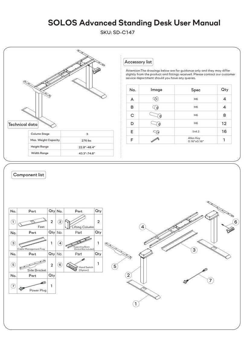
Technical data
Column Stage
Max. Weight Capacity
Height Range
Width Range
27.1"-46.5"(Without table top)
2
220lbs
43.3"-74.8"
Component list
61
3141
71
1222
52
No. Part Qty No. Part Qty
No. Part Qty
Feet Lifting Column
Supporting Beam
(Control Box included)
Cable ManagementTray
Side Bracket
Hand Switch
(Option)
Power Plug
A
C
D
4
B
E
4
F
16
12
8
1
Accessory list
ferAttention:The drawings below are for guidance only and they may dif
slightly from the product and fittings received. Please contact our customer
service department should you have any queries.
No. Image Spec Qty
Allen Key
0.16"x0.16"
St4.2
M6
M6
M6
M6
SKU: SD-ET147
SOLOS V2 Standing Desk User Manual
Ex12
2
1
E
E
STEP 4 TInstall the abletop
The expansion distance of the
supporting beam can be adjusted
according to the actual use.
Attention: When the supporting beam is greater than 67.7",
the installation method is as follows: Method 2 in Step 6.
Loosen
Adjust
Tighten
6
STEP 5 Install the Control Panel
7
Port for
hand switch
Power port
Port for cable
connected to the
lifting column
B
4
3
Bx4
STEP 6 Install the Cable
ManagementTray
Method 1
3
Tighten
Firstly
with
, rotate the screws (B) incompletely into the supporting beam (4)
Allen Key (F), which means do not tighten them. Next, slide one
side of the cable management tray (3) into the screws (B), then the
other side Finally, tighten the screws (B) withAllen Key (F).
1Slide one side
2Buckle the other side
F
0.16"x0.16"
F
0.16"x0.16"
5
F
A
A
5
4
STEP 1 Install the Side Brackets
Attach the side brackets(5) to the ends of the supporting beam (4) using
screws(A) as show with theAllen Key(F).
4
D
F
2
Dx 8
STEP 2 Install the Lifting Columns
Insert the lifting columns (2) into the ends of the supporting beam(4).
Fix the lifting columns using screws(D) with theAllen Key(F).
Install the Feet
C
F
1
2
Cx 8
STEP 3
Place the feet(1) on the bottom of the lifting column(2).
Fix the feet using screws(C) withAllen Key(F).
F
0.16"x0.16"
F
0.16"x0.16"
Ax4
F
0.16"x0.16"
3
4
D
B
B
D
Method 2
Install the cable management tray as Method 1, Step 6.
When the supporting beam stretches over 67.7",
the cable management tray needs to be mounted on
the middle of the supporting beam.
Do not stretch the support
beam beyond this hole
Waste disposal This marking indicates that this product should
not be disposed with other household wastes.
To prevent possible harm to the environment or
human health from uncontrolled waste disposal,
recycle it responsibly to promote the sustainable
reuse of material resources. To return your used
device, please use the return and collection
systems or contact the retailer where the
product was purchased. They can take this
product for environmental safe recycling.
Common fault treatment
g
The following tips w ill help you dete cted and eliminate the c ommon fault
and e rror.If the fault you met is n ot lis ted below, p leas e contact with your
s upplier. Only themanufacturer and profes sionals a re capable for inves tigatin
and correcting thos e fault and error.
1.Check i f all the c ables b e connected well
2.Contact your s upplier or deale r
1. Check i f overloaded, max l oading: 220 lbs;
1. Check if overloaded, m ax loading: 220 lbs;
2. Contact your s upplie r or dealer
2. Contact your s upplier or deale r
1. Contact your s upplie r or dealer
1 .Re pos ition
2.Contact your s upplie r or dealer
(Duty cycle: Max 2min on/18min OFF)
1. Res tart after s us pe nd for 1 8mins w hile
c onne cting with p ower;
2. Contact your s upplie r or dealer;
1. Pre s s "M"and "3" toge ther for 3 s e conds o r
more, afte r he aring continuous b eeping for twice,
it will res tore factory s ettings
2.Contact your s upplier or deale r
Go down but not go up
The motor not move as instructed
Rising In a low Speed
No response while pressing up
arrow/down arrow after connected
with a power supply
No response while long pressing up
arrow/down arrow after connected
with a power supply
Downward Sliding
Frequently Reposition
Overwork
Not enough up& down height
Method
Fault Phenomenon
ionAttent
1. Power supply: AC100V-240V,50/60Hz
2. Service Environment: 0-40
3. Unplug the power plug before cleaning, wipe the dust on surface with slight wet
dishcloth when cleaning, be careful not to let the drops into the internal parts, not loose
the connector.
4. The electric box contains electronic components, metals, plastics, wires etc., so
dispose of it in accordance with each country's environmental legislation, not the
general household waste.
5. Check carefully to ensure correct and complete assembly before using.
6. Be familiar with all functions and program settings of the product before first use.
7. Children are forbidden to play on the product because of unforeseen action when
playing, so any dangerous consequences caused by this improper action will not be on
8. Slight noise caused by the V-ribbed belt or brake system due to structure will not
have any effect on the use of the equipment.
9. Corrosive or abrasive materials are forbidden to clean the equipment. Must ensure
that the cleaner used will not pollute the environment.
10. This appliance can be used by children aged from 8 years and above and persons
with reduced physical, sensory or mental capabilities or lack of experience and
knowledge if they have been given supervision or instruction concerning use of the
appliance in a safe way and understand the hazards involved. Children shall not play
with the appliance.
11. Cleaning and user maintenance shall not be made by children without supervision.
12. If the supply cord is damaged, it must be replaced by the manufacturer, its service
agent or a similarly qualified person in order to avoid a hazard.
13. Please make sure there is no hazard sources in your operating environment. e.g.,
do not litter the tools around.Always be careful to treat the packaging materials in order
to avoid any possible danger , e.g. plastic bag may lead to choking hazard to children.
14. Keep the original package of the equipment if necessary in case of the future use in
transportation.
°C
Dx4
Bx4
F
0.16"x0.16"

Other Solos Indoor Furnishing manuals

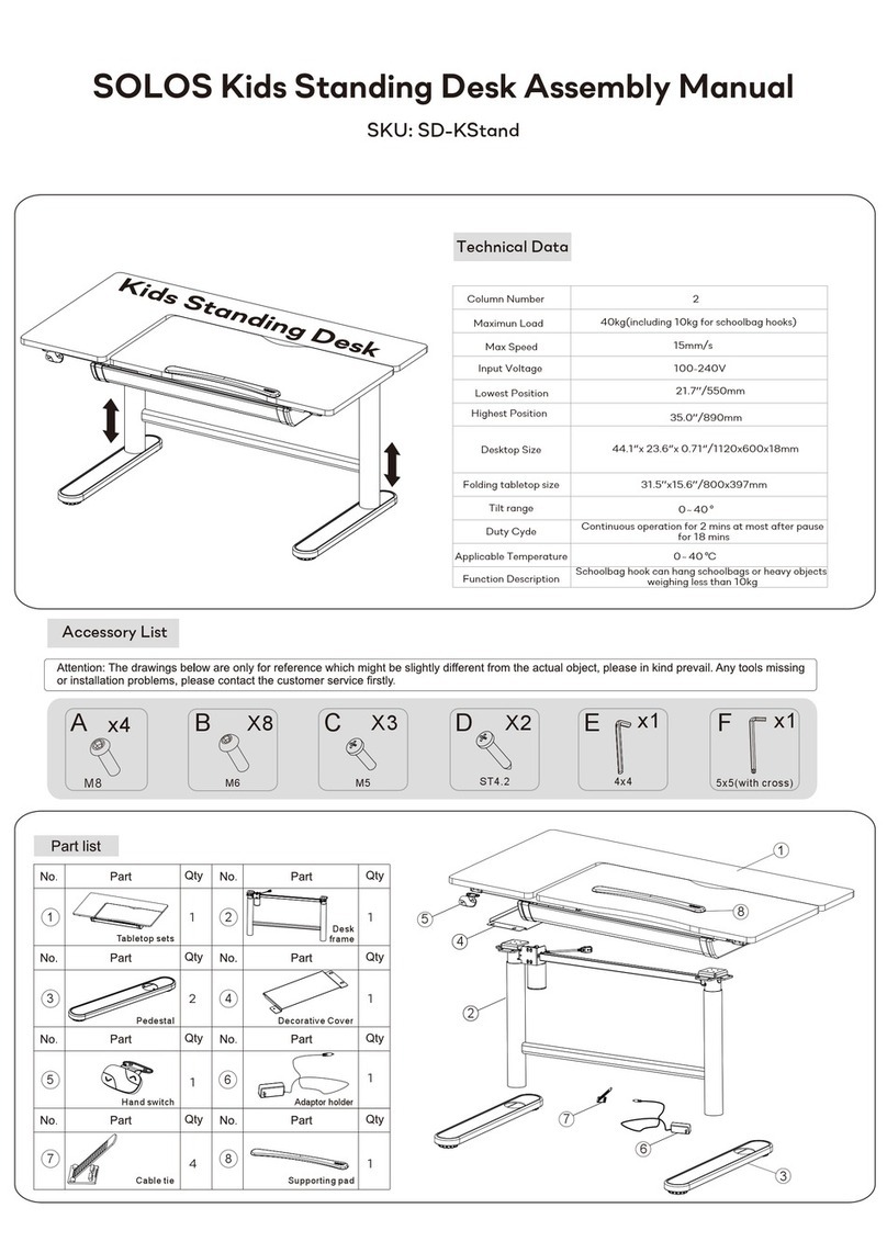
Solos SD-KStand001-WH User manual

Solos

Solos SD-KStand001-WH User manual

Solos SD-GStand-BK User manual

Solos

Solos SD-GStand-BK User manual

Solos SD-B147 User manual

Solos

Solos SD-B147 User manual

Solos L-shaped Standing Desk SD-LD16137-WH User manual

Solos

Solos L-shaped Standing Desk SD-LD16137-WH User manual

Solos SD-KStand User manual

Solos

Solos SD-KStand User manual

Solos SD-C147 User manual

Solos

Solos SD-C147 User manual

Popular Indoor Furnishing manuals by other brands

New Classic Furniture VEGA U3822-30-PBK Assembly instructions

New Classic Furniture

New Classic Furniture VEGA U3822-30-PBK Assembly instructions

OVE CLAUDIA 60 installation manual

OVE

OVE CLAUDIA 60 installation manual

Yaasa Chair White manual

Yaasa

Yaasa Chair White manual

King Living Felix Assembly instructions

King Living

King Living Felix Assembly instructions

Accuride ST8200 quick start guide

Accuride

Accuride ST8200 quick start guide

cimol TAIS 10871 Assembly instruction

cimol

cimol TAIS 10871 Assembly instruction

Suncast GH1732 Assembly instructions

Suncast

Suncast GH1732 Assembly instructions

SEI HZ640200TX Assembly instructions

SEI

SEI HZ640200TX Assembly instructions

Argos Linear 247/6216 Assembly instructions

Argos

Argos Linear 247/6216 Assembly instructions

MBM Romeo Assembly instruction

MBM

MBM Romeo Assembly instruction

KI System 3000 Countertop Assembly instructions

KI

KI System 3000 Countertop Assembly instructions

Leggett & Platt Raven owner's manual

Leggett & Platt

Leggett & Platt Raven owner's manual

East West Furniture CAT-CAP-S Assembly instruction

East West Furniture

East West Furniture CAT-CAP-S Assembly instruction

BROSA Siesta 3 Seater Sofa Bed Assembly guide

BROSA

BROSA Siesta 3 Seater Sofa Bed Assembly guide

Core Products TV 112-OKW Assembly instructions

Core Products

Core Products TV 112-OKW Assembly instructions

Bonaldo ART 220.325.6 manual

Bonaldo

Bonaldo ART 220.325.6 manual

The Interior Gallery TIG-682060 installation guide

The Interior Gallery

The Interior Gallery TIG-682060 installation guide

Next 808953 Assembly instructions

Next

Next 808953 Assembly instructions

manuals.online logo
manuals.online logoBrands
  • About & Mission
  • Contact us
  • Privacy Policy
  • Terms and Conditions

Copyright 2025 Manuals.Online. All Rights Reserved.