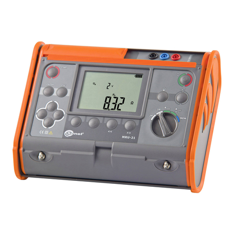
Sonel MZC-306 User manual


OPERATING MANUAL
FAULT LOOP IMPEDANCE METER
MZC-306
SONEL SA
ul. Wokulskiego 11
58-100 Świdnica
Version 1.06 27.01.2016

OPERATING MANUAL MZC-306 version 1.06
2
The MZC-306 meter is a modern, easy and safe in use measuring device. Please acquaint yourself
with the present manual in order to avoid measuring errors and prevent possible problems related to
operation of the meter.

OPERATING MANUAL MZC-306 version 1.06
3
CONTENTS
1SAFETY....................................................................................................................5
2MEASUREMENTS..................................................................................................6
2.1 SELECTION OF GENERAL MEASUREMENT PARAMETERS.........................................6
2.2 REMEMBERING THE LAST MEASUREMENT RESULT ................................................7
2.3 MEASUREMENT OF ALTERNATING VOLTAGE .........................................................8
2.4 CHECKING THE CORRECTNESS OF PE (PROTECTIVE EARTH)CONNECTIONS...........8
2.5 MEASUREMENT OF FAULT LOOP PARAMETERS ......................................................8
2.5.1 Selection of measurement parameters ...........................................................9
2.5.2 Prospective short-circuit current.................................................................10
2.5.3 Measurement of fault loop parameters in the L-N and L-L circuits ............11
2.5.4 Measurement of fault loop parameters in the L-PE circuit .........................13
2.5.5 Measurement of short circuit loop impedance in L-PE circuit protected with
a residual current device (RCD)..................................................................14
3MEMORY OF MEASUREMENT RESULTS.....................................................17
3.1 STORING THE MEASUREMENT RESULTS DATA IN THE MEMORY ...........................17
3.2 VIEWING MEMORY DATA.....................................................................................19
3.3 DELETING MEMORY DATA...................................................................................20
3.3.1 Deleting bank data.......................................................................................20
3.3.2 Deleting the whole memory .........................................................................21
3.4 COMMUNICATION WITH PC.................................................................................22
3.4.1 Set of accessories to connect the meter to a PC ..........................................22
3.4.2 Data transmission........................................................................................22
3.4.3 Software update...........................................................................................23
4TROUBLESHOOTING.........................................................................................24
5POWER SUPPLY OF THE METER...................................................................25
5.1 MONITORING OF THE POWER SUPPLY VOLTAGE...................................................25
5.2 REPLACING BATTERIES (RECHARGEABLE BATTERIES).........................................25
5.3 CHARGING RECHARGEABLE BATTERIES...............................................................26
5.4 GENERAL RULES OF USING THE NICKEL METAL HYDRIDE (NI-MH) BATTERIES..27
6CLEANING AND MAINTENANCE....................................................................28
7STORAGE ..............................................................................................................28
8DISMANTLING AND DISPOSAL.......................................................................28
9TECHNICAL SPECIFICATIONS .......................................................................29
9.1 BASIC DATA ........................................................................................................29

OPERATING MANUAL MZC-306 version 1.06
4
9.2 ADDITIONAL DATA..............................................................................................32
9.2.1 Additional uncertainties according to IEC 61557-3 (Z)..............................32
10 EQUIPMENT .........................................................................................................32
10.1 STANDARD EQUIPMENT.......................................................................................32
10.2 OPTIONAL ACCESSORIES .....................................................................................33
11 MANUFACTURER ...............................................................................................34

OPERATING MANUAL MZC-306 version 1.06
5
1 Safety
MZC-306 meter is designed for performing check tests of protection against electric shock in
mains systems. The meter is used for making measurements and providing results to determine safe-
ty of electrical installations. Therefore, in order to provide conditions for correct operation and accura-
cy of obtained results, the following recommendations must be observed:
Before you proceed to operate the meter, acquaint yourself thoroughly with this manual and ob-
serve the safety regulations and specifications provided by the producer.
Any application that differs from those specified in the manual may result in a damage to the de-
vice and constitute a source of danger for the user.
MZC-306 meters must be operated only by appropriately qualified personnel with relevant certifi-
cates authorising the personnel to perform works on electric systems. Operating the meter by un-
authorised personnel may result in damage to the device and constitute a source of danger for
the user.
Using this manual does not exclude the need to comply with occupational health and safety regu-
lations and with other relevant fire regulations required during the performance of a particular type
of work. Before starting the work with the device in special environments, e.g. potentially fire-
risk/explosive environment, it is necessary to consult it with the person responsible for health and
safety.
It is unacceptable to operate:
a damaged meter which is completely or partially out of order,
a meter with damaged insulation,
a meter stored for an excessive period of time in disadvantageous conditions (e.g. excessive
humidity). If the meter has been transferred from a cool to a warm environment with a high
level of relative humidity, do not start measurements until the meter is warmed up to the am-
bient temperature (approximately 30 minutes).
One should remember that when the word appears on the display, it indicates insufficient
voltage of power supply and the need to charge the accumulator or replace batteries. Measure-
ments performed by means of the meter whose supply voltage is too low are burdened with addi-
tional errors that are impossible to be estimated by the user. Such measurements must not be re-
lied on in order to state correctness of protection of a network tested.
Battery spill and damage to the meter may occur if discharged batteries are left in the meter.
Before measurements may commence, make sure the leads are connected to the appropriate
measurement sockets.
Do not operate a meter with an open or incorrectly closed battery (accumulator) compartment or
power it from other sources than those specified in the present manual.
Repairs may be performed only by an authorised service point.
ATTENTION!
Only standard and additional accessories for a given device should be used, as listed in
the "Equipment" section. Using other accessories may cause damage to measuring termi-
nals and introduce additional measurement uncertainty.
Note:
An attempt to install drivers in 64-bit Windows 8 may result in displaying "Installation
failed" message.
Cause: Windows 8 by default blocks drivers without a digital signature.
Solution: Disable the driver signature enforcement in Windows.

OPERATING MANUAL MZC-306 version 1.06
6
Note:
Due to continuous development of the meter’s software, the actual appearance
of the display, in case of some of the functions, may slightly differ from the dis-
play presented in this operating manual.
2 Measurements
WARNING:
During measurements, the earthed parts and parts accessible in the electrical
installation being tested must not be touched.
WARNING:
During a measurement, switching of the range switch is forbidden because it
may damage the meter and pose a threat to the user.
2.1 Selection of general measurement parameters
Keeping SET button pressed,
turn on the meter and wait for the pa-
rameter selection screen.
Use and buttons to go to the next parame-
ter.
Use and buttons to change the parameter
value. The value or symbol to be changed is
flashing.
Symbol indicates an active parameter, while
symbol - indicates an inactive parameter.
Set the parameters according to the following algorithm:

OPERATING MANUAL MZC-306 version 1.06
7
Parameter
System
voltage
Auto-
OFF
Main result of
fault loop im-
pedance
measurement
Symbol(s)
Press ENTER to validate the changes and go to the
measurement function,
or
Press ESC to go the measurement function without validat-
ing the changes.
Note:
Before the first measurements, select the mains rated voltage Un(110/190V, 115/200V, 127/220V,
220/380V, 230/400V, 240/415V, 290/500V or 400/690V) used in the area where measurements are
made. This voltage value is used for calculating the values of prospective short-circuit current.
- After turning the meter on and displaying the software version, a current nominal system voltage is
displayed: phase voltage in the main field and interphase voltage in the auxiliary one.
2.2 Remembering the last measurement result
The result of the latest measurement is remembered by the meter until a next measurement is
started or measurement settings are changed or the measuring function is changed by means of the
rotary switch. When you go to the voltage measurement screen with the ESC button, you can recall
this result by pressing ENTER. Use the same button to recall the last result after powering the meter
off and on (if the position of function selector has not been changed)

OPERATING MANUAL MZC-306 version 1.06
8
2.3 Measurement of alternating voltage
The meter measures and displays alternating mains voltage before the measurement. This
voltage is measured for the frequencies within the range of 45..65 Hz. The test leads should be con-
nected as for a given measuring function.
2.4 Checking the correctness of PE (protective earth) connections
Note:
WARNING:
When a dangerous voltage is detected on PE conductor, measurements must
be immediately stopped and a fault in the installation must be removed.
- The person making a measurement must ensure that he/she is standing on a non-insulated floor
during the measurement; otherwise the result may be incorrect.
- The threshold value, which triggers the signal of exceeded allowable voltage on PE conduit, is ap-
proximately 50 V.
- In the ZL-PE and ZL-PE RCD functions, when only the phase conductor is connected to one of the
measuring terminals of the meter (L,N,PE), the "PE" alarm will be generated when the contact elec-
trode is touched.
When in the ZL-PE and ZL-PE RCD functions only L and N conductors are connected (respectively to
the meter's L and N terminals), the "PE" alarm may be triggered when the contact electrode is
touched, but sometimes this does not happen (this depends, among other things, on the floor re-
sistance, mains voltage, footwear, etc.).
2.5 Measurement of fault loop parameters
If there are residual current devices in the network tested, they should be bypassed by
bridging for the period of impedance measurement. However, it should be remem-
bered that the tested circuit is modified in this way and the obtained results may slight-
ly differ from the actual results.
After completing measurements, always remove modifications introduced to the tested
system for the period of measurements and check the operation of the residual current
switch.
The above remark does not apply to measurements of short circuit loop impedance
with ZL-PE RCD function.
After connecting the meter
according to the drawing,
touch the contact electrode
with a finger and wait for
about 1 second. When volt-
age is found on PE the meter
displays symbol (error in
the installation; PE connected
to the phase conductor) and
generates a continuous beep.
This option is available for the
ZL-PE measurements.
or

OPERATING MANUAL MZC-306 version 1.06
9
Measurements of fault loop impedance performed downstream of inverters are ineffec-
tive and their results are unreliable. This is due to the instability of internal impedance
in inverter circuits during its operation. The measurements of fault loop impedance
should not be performed directly downstream of inverters.
2.5.1 Selection of measurement parameters
Turn the rotary switch to one of
the loop impedance measure-
ment ranges.
Set the phase conductor length according to the following
algorithm, and according to the rules described in general
parameters setting.
NOTE: The Uni-Schuko WS-xx lead is detected by the me-
ter and it is then impossible to select the cable length (the
symbol is displayed). Before starting the measurement
with test leads terminated with banana plugs, select the ap-
propriate length of the phase conductor, compatible with
the length of the test lead used for measurement.
Parameter
Phase
conductor
length
Approval
Note:
Cables from known manufacturers and selection of the correct length guaran-
tees the declared measurement accuracy.

OPERATING MANUAL MZC-306 version 1.06
10
The leads with Uni-Schuko plugs can be used only in mains below 250V.
2.5.2 Prospective short-circuit current
The meter always measures impedance. The short-circuit current is calculated according to the
following formula:
S
n
kZ
U
I
where: Un- mains rated voltage, ZS- measured impedance.
On the basis of Unrated voltage selected (section 2.1), the meter automatically recognizes the
measurement at phase-to-neutral or phase-to-phase voltage and takes it into account in the calcula-
tions.
If the voltage of the network being tested is outside the tolerance range, the meter will not be able
to determine a proper rated voltage for the short-circuit current calculation. In such a case, horizontal
dashes will be displayed instead a short-circuit current value. The following diagram shows voltage
ranges for which short-circuit current value is calculated.
The voltage range for which the impedance
measurement is performed
The voltage range U L-N, for which the short-
circuit current is calculated
The voltage range U L-L, for which the short-
circuit current is calculated
The voltage range for which the impedance
measurement is performed

OPERATING MANUAL MZC-306 version 1.06
11
2.5.3 Measurement of fault loop parameters in the L-N and L-L circuits
Turn on the meter.
Turn the rotary switch
to the Z/UL-N,L-L position.
Depending on the needs, select the measurement parameters ac-
cording to section 2.5.1.
Connect test
leads according
to the drawing
a) for meas-
urement in the
L-N circuit
or
b) for meas-
urement in the
L-L circuit
The meter is ready for
measurement.
Phase conductor
length or the sym-
bol.
UL-N voltage
Make measurement by pressing
START push-button.
Read the main meas-
urement result: fault
loop impedance ZSor
short-circuit current
IK.
or

OPERATING MANUAL MZC-306 version 1.06
12
To read additional results, press the <<
and >>.
IK
short-circuit
current or
ZS
fault loop
impedance
R
fault loop
resistance
XL
fault loop
reactance
Mains volt-
age at the
time of
measurement

OPERATING MANUAL MZC-306 version 1.06
13
Note:
- Enter the result into memory (see section 3.2) or press ESC to return to the voltage measurement.
- When many measurements are made in short time intervals, the meter may emit a large amount of
heat. As a result of this, the housing of the device may become hot. This is normal and the meter is
equipped with the protection against excessive temperature.
- Minimum interval between successive measurements is 5 seconds. This is controlled by the meter
which displays the message informing that the measurement can be made.
Additional information displayed by the meter
The meter is ready for measurement.
L-N!
Voltage on terminals L and N is not within the measura-
ble range.
Error during the measurement.
Error during the measurement –voltage loss after the
measurement
Short circuit malfunction!
L and N reversed. Signalling works if you use WS-xx lead
or PE lead additionally.
2.5.4 Measurement of fault loop parameters in the L-PE circuit
Turn on the meter.
Turn the rotary switch
to the Z/UL-PE position.
Depending on the needs, select the measurement parameters ac-
cording to section 2.5.1.
Connect test leads
according to one
of the drawings.
or

OPERATING MANUAL MZC-306 version 1.06
14
Checking effectiveness of protection against electric shock
of the enclosure in case of: a) TN b) TT.
The meter is ready
for measurement.
Phase conductor
length or the
symbol.
UL-PE voltage
Make measurement by pressing START push-
button.
Remaining issues connected with the measurements are the same as those described for meas-
urements in L-N circuit or L-L circuit.
Note:
- If you do not use the lead with AC power plug, a double cable measurement is possible.
Additional information displayed by the meter
The meter is ready for measurement.
L-N!
For the lead with the plug - voltage on terminals L and N
is not within the measurable range.
L-PE!
Voltage on terminals L and PE is not within the measura-
ble range.
All remaining messages as in case of measurement in L-N and L-L circuit.
2.5.5 Measurement of short circuit loop impedance in L-PE circuit protected
with a residual current device (RCD)
The MZC-306 enables the fault loop impedance measurements without altering the mains with
RCD's with the rated current of at least 30mA.

OPERATING MANUAL MZC-306 version 1.06
15
Turn on the meter.
Turn the rotary switch
to position .
Depending on the needs, select the measurement parameters ac-
cording to section 2.5.1.
Connect test leads according to one of the drawings.
Remaining issues connected with the measurements are the same as those described for meas-
urements of the L-PE circuit.
Note:
- Maximum measurement time is about 32 seconds. The measurement can be interrupted by press-
ing the ESC button.
In the electrical installations where RCD switches are used with short-circuit current of 30 mA, the
sum of leakage currents of the installation and the test current may cut the RCD. If this happens, try
to reduce the leakage current in the tested mains (for example by disconnecting loads).

OPERATING MANUAL MZC-306 version 1.06
16
Additional information displayed by the meter
The meter is ready for measurement.
L-N!
Voltage on terminals L and N is not within the measura-
ble range.
L-PE!
Voltage on terminals L and PE is not within the measura-
ble range.
Conductor N is not connected.
This message displayed after the measurement indicates
major noise in the system during the measurement. The
measurement result may be affected by a large, unspeci-
fied error.
All remaining messages as in case of measurement in L-N and L-L circuit.

OPERATING MANUAL MZC-306 version 1.06
17
3 Memory of measurement results
MZC-306 meters are equipped with the memory that can store 3500 single measurement results.
The whole memory is divided into 10 memory banks with 99 cells in each bank. Thanks to dynamic
memory allocation, each of the memory cells can contain different quantity of single measurement re-
sults, depending on the needs. Optimal use of the memory can be ensured in this way. Each meas-
urement result can be stored in a memory cell marked with a selected number and in a selected
memory bank. Thanks to this, the user of the meter can, at his/her option, assign memory cell num-
bers to individual measurement points and the memory bank numbers to individual facilities. The user
may also perform measurements in any chosen sequence and repeat them without losing other data.
Memory of measurement results is not deleted when the meter is switched off. Thanks to this,
the data can be later read or sent to a computer. The number of a current memory cell or memory
bank is not changed either.
Note:
- Results of measurements performed for all measuring functions can be stored in one
memory cell.
- After each entry of the measurement result to the cell, its number is automatically incremented. Set
the appropriate cell number to allow entering to a single cell of successive measurement results relat-
ing to a given measuring point (facility).
- Only the results of measurements triggered by START push-button may be stored in the memory.
- It is recommended to delete the memory after reading the data or before performing a new series of
measurements that may be stored into the same memory cells as the previous ones.
3.1 Storing the measurement results data in the memory
Press ENTER after finishing the measurement.
The meter is in the memory storing mode.
You can change a cell number by pressing and a bank number by pressing and .
The cell is empty.
The cell contains the
result of the same type
which is to be entered.

OPERATING MANUAL MZC-306 version 1.06
18
The cell contains the
result of a different type
than is to be entered.
The cell is completely
full.
You can view different types
of results and their compo-
nents using buttons << ,>>.
Select the bank and cell number or leave the
current number. Then press ENTER again. The
screen (shown below) appears for a moment,
accompanied by three short beeps, and then
the meter returns to display the last result of the
measurement.
An attempt to overwrite a result causes
the warning symbol to appear.
This manual suits for next models
1
Table of contents
Other Sonel Measuring Instrument manuals

Sonel
Sonel MIC-10 User manual

Sonel
Sonel MRU-120 User manual

Sonel
Sonel MRU-120HD User manual

Sonel
Sonel WMGBMZC304F User manual

Sonel
Sonel MIC-10k1 User manual

Sonel
Sonel MPI-502 User manual

Sonel
Sonel MMR-620 User manual

Sonel
Sonel MRU-10 User manual

Sonel
Sonel KT-256 User manual

Sonel
Sonel MIC-2 User manual

Sonel
Sonel CMP-1010 User manual

Sonel
Sonel MZC-305 User manual

Sonel
Sonel MRU-21 User manual

Sonel
Sonel MIC-5010 User manual

Sonel
Sonel MPI-505 User manual

Sonel
Sonel MMR-640 User manual

Sonel
Sonel MPI-540 User manual

Sonel
Sonel MPI-525 User manual

Sonel
Sonel CMP-3kR User manual

Sonel
Sonel LXP-10B User manual