Sonel SRM-0R1-4K1 User manual


USER MANUAL
HIGH-CURRENT
DECADE RESISTOR
SRM-0R1-4k1
SONEL S.A.
Wokulskiego 11
58-100 Świdnica
Version 1.03 24.05.2021

SRM-0R1-4k1 –USER MANUAL
2
CONTENTS
1Introduction .................................................................................................................................3
2Intended use................................................................................................................................4
3Technical specifications .............................................................................................................4
4Structure and principle of operation ..........................................................................................5
5Marking and sealing....................................................................................................................7
6General guidelines for using the device ....................................................................................7
7Safety measures..........................................................................................................................7
8Operating the device...................................................................................................................7
8.1 Procedures for adjusting the resistance of the device..............................................8
8.1.1 Adjusting the first decade...............................................................................................8
8.1.2 Adjusting the second decade.........................................................................................8
8.1.3 Adjusting the third decade..............................................................................................9
8.1.4 Adjusting the fourth decade............................................................................................9
8.1.5 Adjusting the fifth decade.............................................................................................10
8.1.6 Simulation of fault loop impedance...............................................................................10
9Calibration of the device...........................................................................................................11
10 Operation and maintenance......................................................................................................11
11 Transport....................................................................................................................................12
11.1 Packaging .............................................................................................................. 12
11.2 Transport conditions............................................................................................... 12
12 Manufacturer..............................................................................................................................12
SRM-0R1-4k1 –USER MANUAL
3
NOTE!
Due to ongoing improvement works on the product, enhancing its technical and opera-
tional parameters, the design of the device may be subject to minor changes not speci-
fied in this publication.
Before operating the device, store it in normal climatic conditions for at least 12 hours.
Before operating the device, it must be earthed using the connector on its front pan-
el. Then, connect the power cord to the appropriate connector on the back of the
device. Operating the device without earthing is prohibited.
After connecting SRM-0R1-4k1 to the mains, set the device in a manner that does not
prevent its disconnection.
1 Introduction
This manual contains information about the design and operation of SRM-0R1-4k1 high-current
decade resistor, including its operating limits and operational safety measures. The manual is intended
for persons working with the set, as well as for the operating/maintenance personnel.
Symbols shown on the instrument:
Read the manual before using the instrument. Strictly comply with the safety rules and
manufacturer's recommendations.
Alternating current
Operational earthing terminal
Warning, dangerous voltage

SRM-0R1-4k1 –USER MANUAL
4
2 Intended use
SRM-0R1-4k1 is a high-current decade resistor designed for simulation and inducing fault loop
resistance using mains voltage of 220/380 V (230/400 V), 50 Hz AC.
SRM-0R1-4k1 high-current decade resistor is used as a reference device for calibration and
certification tests of measuring instruments included in MZC, MIE, MRP, MPI series and others
according to the parameters of "phase-neutral", "phase-to-earth" "phase-PE" "phase-phase" fault loop,
applying a short-term (30-40 ms) test current of 45 A.
SRM-0R1-4k1 high-current decade resistor (hereinafter: the device) provides a gradual resistance
adjustment in the range from 0.1 Ω to 4111 Ω, within the allowable basic error ± 0.1% in the first
decade and up to ± 0.05% in other decades.
The device has a high allowable dissipation power, making it useful for measuring circuits.
Resistors of the device meet all requirements for decade resistors to be used in calibration
laboratories and for testing measuring instruments and may be used in other AC/DC measuring
systems.
3 Technical specifications
Decade No.
of the
device
Nominal resistance values [Ω]
Maximum
permissible
measurement
error
Maximum surge
current
(30 - 40 ms) [A]
1st decade
0.1 / 0.2 / 0.3 / 0.4 / 0.5 / 0.6 / 0.7 / 0.8 / 0.9 / 1.0
± 0.001R
45
2nd decade
1 / 2 / 3 / 4 / 5 / 6 / 7 / 8 / 9 / 10
± 0.0005R
35
3rd decade
10 / 20 / 30 / 40 / 50 / 60 / 70 / 80 / 90 / 100
± 0.0005R
15
4th decade
100 / 200 / 300 / 400 / 500 / 600 / 700 / 800 / 900 / 1000
± 0.0005R
2
5th decade
1000 / 2000 / 3000
± 0.0005R
0.3
Initial resistance of the device (the resistance during setting the switches of all the decades to
'zero' indication) does not exceed 0.025 Ω.
The device is designed to operate in the ambient temperature range from 10°C to 30°C, relative
humidity from 25% to 60% and atmospheric pressure from 630 to 800 mm Hg. Storage conditions of
the device are described in section 11 of this manual.
Additional technical parameters
Permissible limit of the additional measurement error caused by changes in ambient tempera-
ture (compared to the normal operating temperature range) is equal to the accuracy precision
class.
a) nominal temperature ........................................................................................................ (20 ± 5)°C
b) operating temperature range ...........................................................................................(20 ± 10)°C
c) maximum operating voltage .................................................................................................... 450 V
d) measurement cycle duration Тmeas ................................................................................30-40 ms
e) cooling time (pause) Тpaus..................................................................at Umeas. up to 230 V 20 s
............................................................................................................at Umeas. up to 450 V 25 s
f) insulation resistance............................................................................................................>100 MΩ
g) dimensions .......................................................................................................500 x 340 x 170 mm
h) weight..........................................................................................................................approx. 12 kg
SRM-0R1-4k1 –USER MANUAL
5
4 Structure and principle of operation
The front panel of the device with functional switches is shown in Fig. 1; the connection diagram of
decades in the device is shown in Fig. 2; the connection diagram of the device when simulating fault
loop impedance is shown in Fig. 3.
SRM-0R1-4k1 consists of five decades connected in series. The first position is for the decade
with lowest resistance values (Ω x 0.1), and the last for the decade with highest resistance values (x
1000 Ω). Setting the resistance starts from the lowest decade and ends at the highest decade, always
remembering that all the decades set below must have the maximum value.
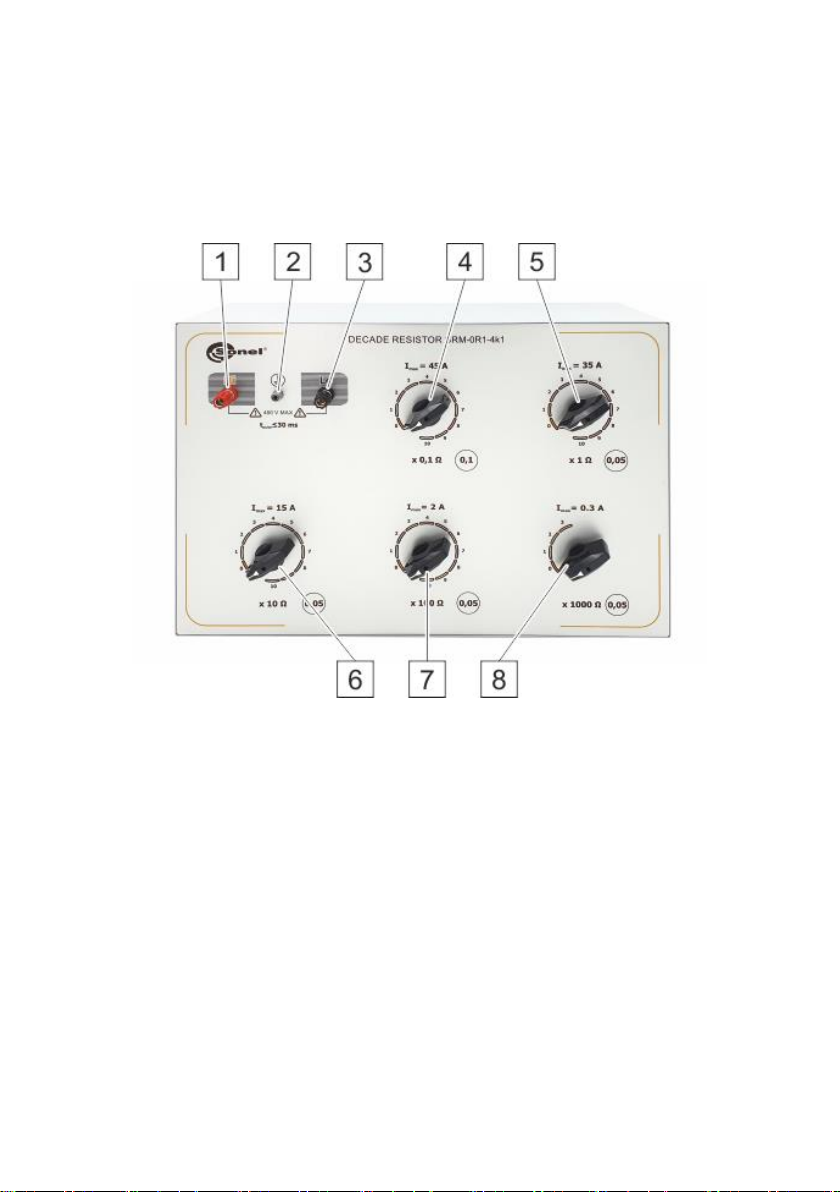
Fig. 1. Front panel of SRM-0R1-4k1
1 - connector for external voltage phase (H)
2 –connector for protective conductor (PE)
3 - connector for connecting tested measuring device (L)
4 - rotary switch (multiplier) of the first decade
5 - rotary switch (multiplier) of the second decade
6 - rotary switch (multiplier) of the third decade
7 - rotary switch (multiplier) of the fourth decade
8 - rotary switch (multiplier) of the fifth decade

SRM-0R1-4k1 –USER MANUAL
6
Fig. 1. Side panel of SRM-0R1-4k1
1 - fans
2 - switch of cooling system
3 - fuse (F 0.5 A)
3 –connector for the power cord
Fig. 2. Connection diagram of decades in the device
Fig. 3. Measuring system for testing fault loop meters
Tested
measuring device
SRM-0R1-4k1
SRM-0R1-4k1 –USER MANUAL
7
5 Marking and sealing
Name, symbol and trade mark of the device are placed at the top of its front panel.
Serial number and year of manufacture of the device are shown on the rear panel.
The set received by the quality control department is sealed with self-adhesive seals (self-
destructing when device is opened), located on the latches of the top panel.
6 General guidelines for using the device
Maintenance activities on the device are carried out in order to ensure its interrupted operation
and readiness for use.
During the maintenance activities on the device, check the following:
- intact seals;
- completeness of the device;
- external mechanical damage;
- cleanliness of connectors and sockets;
- condition of coatings, electroplating and precision of engraving;
- condition of connecting cables and cable glands.
During operation, the measuring device must not be placed on its front or rear panel, as this may
damage its controls and power cord connection.
7 Safety measures
The instrument may be operated only by persons with appropriate training in safe work with
electrical equipment.
Before connecting the device to the mains, make sure the power cord is intact.
Before commencing measurements, make sure the test leads are connected to the appropriate
measurement sockets;
Repairs must be performed only by an authorised service point.
NOTE!
It is forbidden to use the device without activating the cooling system and/or with impaired
air exhaust.
8 Operating the device
Task (example): the resistance value must be at the level of 2 Ω. To achieve this, set the decade
marked as 10 x 0.1 into position "10" (1 Ω), and the decade marked as 10 x 1 Ω set into position "1" (1
Ω); then the required value of 2 Ω is achieved. Using the above method of adjustment, the circuit will
connected to 11 resistors and each of them will generate a proportional part of the power consumed in
the circuit.
It is not allowed to set the second decade in position "2" (2 Ω), when decade 10 x 0.1 Ω is set in
position "0" as the power provided to resistor 2 Ω, in the second decade will exceed by 100% the
permissible dissipation power.
The algorithm of correct resistance setting for decades is presented in section 8.1.
NOTE!
Failure to follow the above set-up procedure may lead to excessive overheating of the
device and its damage.
SRM-0R1-4k1 –USER MANUAL
8
8.1 Procedures for adjusting the resistance of the device
8.1.1 Adjusting the first decade
In the first decade (marked as 10 x 0.1 Ω) any resistance value can be set in the range of 0.1 Ω ...
1.0 Ω (a higher decade must be set to "0") - Fig. 4.
Fig. 4. Connection diagram for adjusting the resistance of the first decade
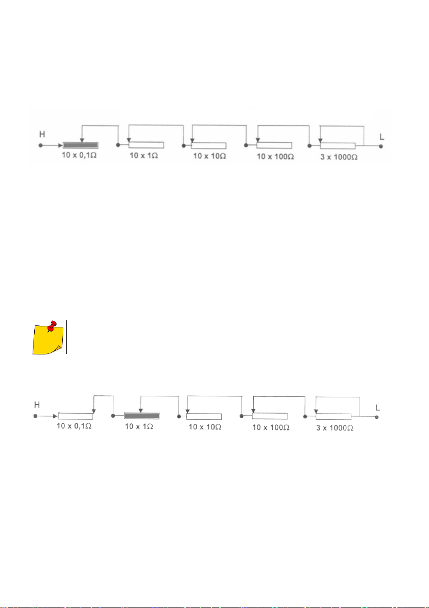
8.1.2 Adjusting the second decade
In order to start the adjustment of resistance in the second decade, the first decade must remain in
position "10" (i.e. a value of 1 Ω) - Fig. 5.
In the second decade (marked as 10 x 1 Ω) the user may set any resistance value in the range
from 1 Ω to 11 Ω (higher decades must be set at "0"), thus the total resistance value obtained is in the
range of: Rmin < R < Rmax.
Rmin = 1 Ω + 1 Ω = 2 Ω
Rmax = 1 Ω + 10 Ω = 11 Ω
Any other settings are not recommended, e.g. 3.2 Ω; 5.7 Ω etc.
Fig. 5. Connection diagram for adjusting the resistance of the second decade
Position 10
1 Ω
Position 0
Position 0
Position 0
Position 0
Position 0
Position 0
Position 0

SRM-0R1-4k1 –USER MANUAL
9
8.1.3 Adjusting the third decade
In order to start the adjustment of resistance in the third decade, the first decade must remain in
position "10" (i.e. the value of 1 Ω) and the second decade must be set at "9" (i.e. the value of 9 Ω) –
Fig. 6.
In the third decade (marked as 10 x 10 Ω) the user may set any resistance value in the range from
10 Ω to 110 Ω (higher decades must be set at "0"), thus the total resistance value obtained is in the
range:
from Rmin =1 Ω + 10 Ω +10 Ω = 21 Ω
to Rmax = 1 Ω + 10 Ω + 100 Ω = 111 Ω
Fig. 6. Connection diagram for adjusting the resistance of the third decade
Any settings other than those specified above are not recommended.
8.1.4 Adjusting the fourth decade
In order to start the adjustment of resistance in the fourth decade, the first decade must remain in
position "10" (i.e. the value of 1 Ω), the second decade must be set at "9" (i.e. the value of 9 Ω) and
the third decade must be set at "9" (i.e. the value of 90 Ω)– Fig. 7.
In the fourth decade (marked as 10 x 100 Ω) the user may set any resistance value in the range
from 100 Ω to 1100 Ω (higher decades must be set at "0"), thus the total resistance value obtained is
in the range:
from Rmin =1 Ω + 10 Ω +100 Ω + 100 Ω = 211 Ω
to Rmax = 1 Ω + 10 Ω + 100 Ω + 1000 Ω = 1111 Ω
Fig. 7. Connection diagram for adjusting the resistance of the fourth decade
Any other settings are not recommended.
Position 0
Position 0
Position 10
1 Ω
Position 9
9 Ω
Position 10
1 Ω
Position 9
9 Ω
Position 9
90 Ω
Position 0

SRM-0R1-4k1 –USER MANUAL
10
8.1.5 Adjusting the fifth decade
In order to start the adjustment of resistance in the fifth decade, the first decade must remain in
position "10" (i.e. the value of 1 Ω), the second decade must be set at "9" (i.e. the value of 9 Ω), the
third decade must be set at "9" (i.e. the value of 90 Ω) and the fourth decade must be set at "9" (i.e.
the value of 900 Ω) – Fig. 8.
In the fifth decade (marked as 3 x 1000 Ω) the user may set any resistance value in the range
from 1000 Ω to 4000 Ω, thus the total resistance value obtained is in the range:
from Rmin =1 Ω + 10 Ω +100 Ω + 1000 Ω + 1000 Ω = 2111 Ω
to Rmax = 1 Ω + 10 Ω + 100 Ω + 1000 Ω + 3000 Ω = 4111 Ω
Fig. 8. Connection diagram for adjusting the resistance of the fifth decade
Fault loop measurement devices may be checked starting from the highest resistance value. For
this purpose, set the decades of the device as shown in Fig. 8. Then, the adjustment starts from the
fifth decade, and then the values of the fourth, third, second and first decade are successively
reduced.
The described method of setting the device ensures that all used resistors are included in the
series, significantly reducing the power dissipated on them.
8.1.6 Simulation of fault loop impedance
When it is necessary to simulate the fault loop impedance in series using the device, activate an
external calibration coil. Connection diagram of the measuring circuit is shown in Fig. 9.
Fig. 9. Simulation of fault loop impedance
Position 10
1 Ω
Position 9
9 Ω
Position 9
90 Ω
Position 9
900 Ω
Tested
measuring
device
SRM-0R1-4k1
W

SRM-0R1-4k1 –USER MANUAL
11
9 Calibration of the device
It is advised to check the device every 12 months.
10 Operation and maintenance
The operator carrying out the measurements using SRM-0R1-4k1, may perform the following
maintenance activities:
fuse replacement –type F 0.5 A;
cleaning the device.
NOTE!
Before replacing the fuse, it is mandatory to disconnect the device from the power supply.
The housing of SRM-0R1-4k1 may be cleaned with a soft, dry cloth. Do not use solvents or
abrasive cleaners (powders, pastes, etc.). The electronic circuit of SRM-0R1-4k1 does not require
cleaning, except for the sockets of test leads.
Any other maintenance works are performed only by authorized service of the manufacturer.
The cooling system of the device is powered from mains - AC 230 V, 50 Hz.
SRM-0R1-4k1 packed in the shipping box may be transported by any means of transport to any
distance.
SRM-0R1-4k1 packaged in the shipping box, should be stored befrore operation at the ambient
temperature of 5°C ... 40°C and relative humidity of 80% at 25 ° C
When storing SRM-0R1-4k1 without packaging, the ambient temperature must be in the range of
10°C - 35°C and relative humidity up to 80% at +35°C.
Storage rooms/areas must be free from dust, fumes acids, and corrosive alkalis.
Standard environmental conditions
up to 2000 m above sea level;
operating temperature 10°C…35°С
storage temperature -20°C…+60°C
at the maximum relative humidity of 80% for temperatures up to 31°С and a linear decrease
in relative humidity to 50% at a temperature increase to 40°С
Shelf life in the manufacturer's original packaging: 5 years.
SRM-0R1-4k1 –USER MANUAL
12
11 Transport
11.1 Packaging
To ensure safety of the device during transport, a protective cardboard box is used.
Pack the device in the following order:
put the device placed in a plastic bag, which must be tied and inserted in the box,
insert documentation in a separate plastic bag and place it on the packaged device or be-
tween the side wall of the box and the device,
wrap the box with a plastic tape and seal it.
11.2 Transport conditions
The device packed in the transport box may be shipped using all kinds of transport and to any
distance.
During the transport, the packaging must be protected against rain and dust. Do not tilt the device.
12 Manufacturer
The manufacturer of the device and provider of guarantee and post-guarantee service:
SONEL S.A.
Wokulskiego 11
58-100 Świdnica
Poland
tel. +48 74 858 38 60
fax +48 74 858 38 09
E-mail: ex[email protected]
Web page: www.sonel.pl
NOTE!
Service repairs must be performed only by the manufacturer.
Made in Russia.


SRM-0R1-4k1 –USER MANUAL
14
Table of contents
Other Sonel Laboratory Equipment manuals


Popular Laboratory Equipment manuals by other brands


Fluke Biomedical
Fluke Biomedical INCU Operator's manual

Agilent Technologies
Agilent Technologies Graphite Tube Atomizer GTA 120 user guide

Parker Laboratories
Parker Laboratories Thermasonic Gel Warmer user manual

Diesse
Diesse cube 30 touch user manual

Fritsch
Fritsch PULVERISETTE 1 classic line operating instructions

ZINEXTS
ZINEXTS ZiXpress 32 Dx system instruction manual


