SONOPAN DLM-102 User manual

April 2019
DLM-102
CLASS II
SOUND LEVEL METER
Instruction manual
This manual describes operation of the DLM-101 meter with firmware version
1. .0021. The firmware version number can be viewed on the welcome screen
which is displayed after turning on the meter (the exact description can be found
in section Błąd! Nie można odnaleźć źródła odsyłacza. of this manual).
PPUH SONOPAN Sp. z o.o.
ul. Ciołkowskiego 2/2 15-950 Białystok Poland
phone +48 85 742 36 62
sonopan@sonopan.com.pl
https://www.sonopan.com.pl/

2
TABLE OF CONTENTS
1. INSTRUMENT CHARAKTERISTRICS..............................................................................................................3
1.1. Accessories.................................................................................................................................................4
1.2. System configuration ..............................................................................................................................4
1.3. Measured quantities................................................................................................................................4
1.4. Specifications ............................................................................................................................................4
1.5. Influence of operating environment...................................................................................................8
1.6. Influence of instrument accessories....................................................................................................8
2. CONTROLLING OF THE INSTRUMENT ........................................................................................................9
2.1. Control keys...............................................................................................................................................9
2.2. Input and output connectors of the instrument ..............................................................................9
2.3. Default instrument settings............................................................................................................... 11
2.4. Preparation of the instrument to operation.................................................................................. 11
3. OPERATION.................................................................................................................................................... 11
3.1. Instrument data plate .......................................................................................................................... 12
3.2. Results...................................................................................................................................................... 13
3.3. Date and time......................................................................................................................................... 14
3.4. Measures memory................................................................................................................................. 14
3.5. Time history memory............................................................................................................................ 15
3.6. Calibration............................................................................................................................................... 16
4. RECOMENDATIONS FOR INSTRUMENT USE ......................................................................................... 17
4.1. Recommendations for correct performing of measurements................................................... 17
4.2. Internal battery...................................................................................................................................... 18
4.3. Calibration of the instrument ............................................................................................................ 18
4.4. Warranty.................................................................................................................................................. 19
4.4.1. Complaint instructions for the purchaser: .............................................................................. 19
4.5. Maintenance and repair....................................................................................................................... 19
4.6. Firmware.................................................................................................................................................. 19
5. CE MARKING AND CONFORMANCE TO EU COUNCIL DIRECTIVES.................................................. 20
Appendix A. Filter characteristics............................................................................................................... 21
Appendix B. Directional characteristics .................................................................................................... 22

3
1. INSTRUMENT CHARAKTERISTRICS
DLM-102 is fully digital single range integrating sound level meter with type 1 accuracy. Easy
operation wide range and small dimensions allow measurements of noise in many areas. This
meter is ideal for company health and safety inspector or building inspector controlling building
work. The low price enables use of meter where until now the noise was not evaluated because
of high cost of measuring instruments.
Internal Li-ION battery provides long-term measurements on single charging and easy to read
backlit display allows comfort use in tight dark places.
The large internal memory allows the use of the DLM-102 meter in environmental noise
monitoring and the ability to record the measurement history log with 100ms interval enables
its use also in the assessment of aircraft noise.
microphone
connector
charger
connector
LED to signal charger
attaching
RS-232 connector
USB connector
Fig. 1.1. DLM-102 sound level meter – general view.

4
PN-EN 61672-1:2005
PLT1113
DLM-102
Nr.
Klasa 2
Fig. 1.2. DLM-102 sound level meter – data plate.
1.1. Accessories
Basic accessories:
• Charger 6WZS 12/400 (Tatarek).
• OP60/4 microphone windscreen.
• RS-232 cable (DB9F-RJ10) 1.8m.
• USB cable (USBA-USBB mini) 1.8m.
• Carrying case.
• Instruction manual.
• Declaration of Conformity.
• Warranty Card.
Additional accessories:
• KA-10 type 2 acoustic calibrator.
• Supporting stand for the instrument SMR (1 5m height).
1.2. System configuration
Basic configuration:
• DLM-102 sound level meter (Sonopan).
• MK-401 ¼” measurement microphone (Sonopan).
• OP60/4 microphone windscreen.
Other accessories specified in section 1.1 are optional.
1.3. Measured quantities
Sound level meter allows simultaneous measurement:
• with A or C frequency weighting:
- current RMS sound level (with SLOW or FAST time weighting) e.g. LAF
- minimum RMS sound level (with SLOW or FAST time weighting) e.g. LAFmn
- maximum RMS sound level (with SLOW or FAST time weighting) e.g. LAFmx
- time-average (equivalent continuous) sound level e.g. LAeq.
- sound exposure level e.g. LAE.
• with C frequency weighting:
- current peak sound level LCPk
- maximum peak sound level LCMPk
• measurement time.
1.4. Specifications
Instrument meets the requirements of following standards:
EN 61672-1:2014 Electroacoustics. Sound level meters. Part 1:
Specifications.
Meter belongs to the group X as defined in EN 61672-1:2003.
5
Specification (for microphone sensitivity 12.5mV/Pa):
• Accuracy class 2
• Frequency weightings A C
• Time weightings SLOW FAST
• Readout resolution:
- measure 0.1dB
- calibration 0.01dB
• Maximum value of sound pressure
causing no damage to the meter 150dB
• Maximum unweighted sound pressure level
causing no activating of overload indicator 137.9dB
• Maximum electrical signal value causing no
damage to the instrument (applied using electrical
input facility) 5.34Vp-p
• The way of insert electrical signals into the meter
input directly from the generator with
internal impedance ≤ 600Ω
• Reference conditions
- type of sound field free
- reference frequency 1000Hz
- reference sound pressure level 94dB
- reference level range 40 - 135dB
- sampling frequency 41.7kHz
- microphone reference direction microphone symmetry axis
- microphone reference point microphone diaphragm centre
- reference orientation sound wave arriving from
reference direction
- reference temperature +23°C
- reference humidity 50%
- reference static pressure 101.325kPa
• Starting point at which to begin tests of level
linearity deviation on the reference level range reference sound pressure level
• Permissible error for sinusoidal reference signal
(progressive sound wave incident perpendicularly
to microphone diaphragm 94dB 1000Hz) ≤ ±1.0dB
• Total range for LA sound level and LAeq
time-average sound level) 40 – 135dBA
• Measuring ranges at specified frequencies for sound level (L) and time-average sound
level (Leq)
31.5Hz 1kHz 4kHz 8kHz
A
40-98dBA 40-135dBA 40-137dBA 40-135dBA
C 45-135dBC 45-135dBC 45-135dBC 45-135dBC
• Total range for LCPk peak sound level 50 – 138dBC
• Self-generated noise
without microphone with MK-401 microphone
A
≤19dB ≤35dB
C ≤20dB ≤43dB
• Measurement duration with 1s resolution 999 hours 59 minutes 59 seconds
• Warm-up time
- after turn-on 1 minute
- after environmental conditions change 15 minutes
• Power supply
- internal battery Li-ION 7.2V 700mAh
- charger 6WZS 12/400 (Tatarek)
• Minimum operating voltage of internal battery 6.6V
6
• Operating temperature range 0 ÷ +40°C
• Storage temperature range -10 ÷ +50 °C
• Operating humidity range ≤ 90% (without condensation)
• Operating static pressure range 65 ÷ 108kPa
• Electromagnetic emission within the limits specified in
EN 61672-1:2002 (maximum
emission when operating with
charger)
• Dimensions (without microphone) 194 x 81 x 30 mm
• Continuous operating time (battery fully charged) 16h
• Weight 400g
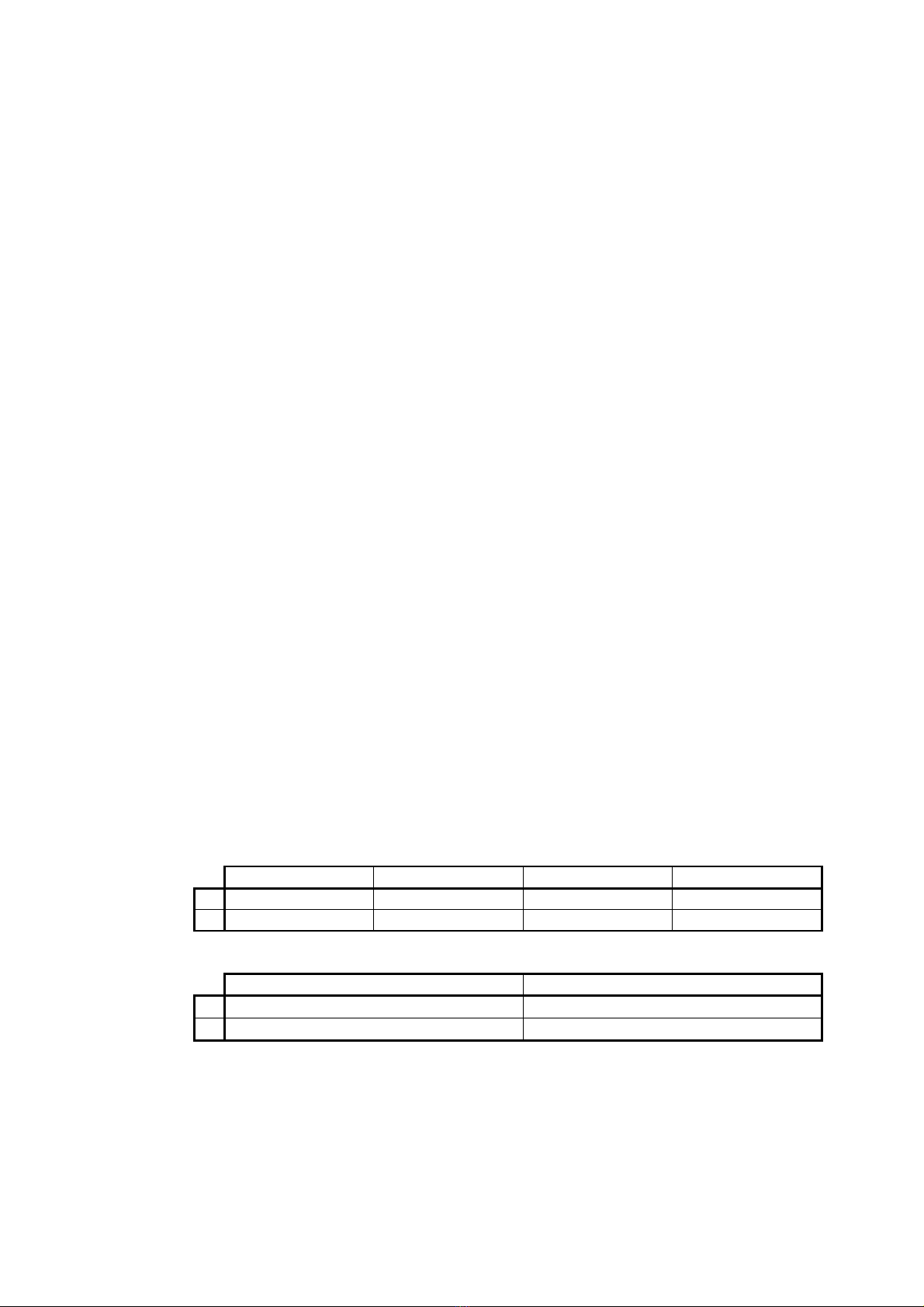
• Nominal corrections for effects of reflection
from instrument case (free field 0° incidence) See table below
f [Hz]
250 315 400 500 630 800 1000 1250 1600 2000 2240
dL [dB]
0.01 0.05 0.11 0.12 0.40 0.17 0.01 -0.22 -0.23 -0.01 0.22
U [dB]
≤ 0.10
f [Hz]
2500 2800 3150 3550 4000 4500 5000 5600 6300 7100 8000
dL [dB]
0.24 -0.53 0.27 0.23 -0.34 0.31 0.18 -0.47 0.37 0.03 -0.02
U [dB]
≤ 0.12
f [Hz]
8500 9000 9500 10000
10600
11200
11800
12500
13200
14000
15000
dL [dB]
0.00 -0.33 -0.29 0.28 0.39 -0.27 0.01 -0.41 0.37 -0.18 0.26
U [dB]
≤ 0.12 ≤ 0.17
f [Hz]
16000
17000
18000
19000
20000
dL [dB]
0.38 -0.30 -0.30 -0.08 -0.26
U [dB]
≤ 0.17
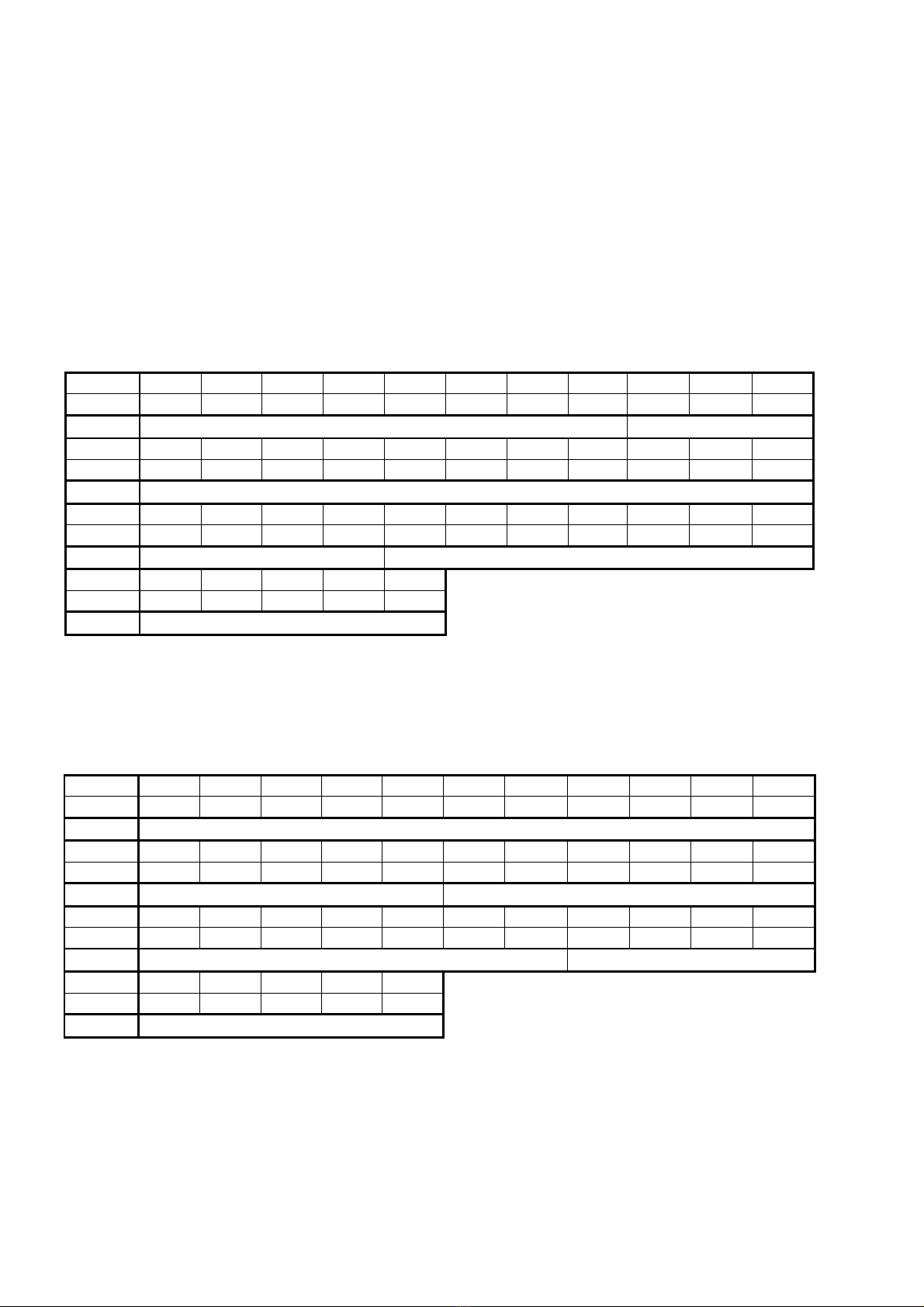
• Differences between MK-401 microphone free
field frequency response at 0° incidence and
multi-frequency acoustic calibrator response;
expanded (k=2) uncertainty of the determination
of these differences: See table below and Fig. 1.3.
f [Hz]
250 315 400 500 630 800 1000 1250 1600 2000 2240
dL [dB]
0.00 0.01 0.03 0.04 0.00 0.07 0.07 0.12 0.09 -0.03 0.06
U [dB]
≤ 0.25
f [Hz]
2500 2800 3150 3550 4000 4500 5000 5600 6300 7100 8000
dL [dB]
-0.02 -0.06 -0.03 0.09 0.15 0.18 0.18 0.35 0.41 0.54 0.36
U [dB]
≤ 0.25 ≤ 0.45
f [Hz]
8500 9000 9500 10000
10600
11200
11800
12500
13200
14000
15000
dL [dB]
0.67 0.79 0.81 0.76 0.78 0.95 1.37 1.73 1.61 1.84 2.56
U [dB]
≤ 0.45 ≤ 0.58
f [Hz]
16000
17000
18000
19000
20000
dL [dB]
2.78 3.12 3.54 4.08 4.10
U [dB]
≤ 0.58
7
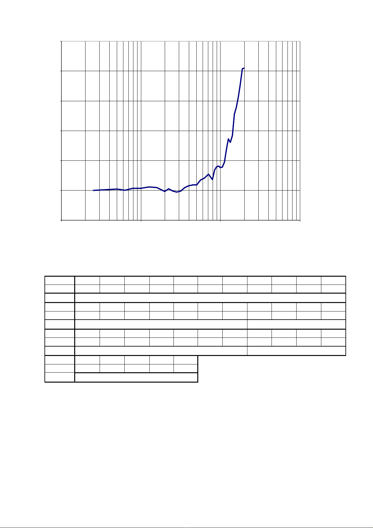
-1,0
0,0
1,0
2,0
3,0
4,0
5,0
100 1000 10000 100000
Fig. 1.3. Free-field correction for MK-401 microphone (0° incidence).
Table below and Fig. 1.4 show typical free-field frequency response of MK-401 microphone.
f [Hz]
250 315 400 500 630 800 1000 1250 1600 2000 2240
dL [dB]
0.00 -0.01 -0.01 0.00 -0.03 -0.02 -0.05 -0.02 -0.02 -0.14 -0.02
U [dB]
≤ 0.23
f [Hz]
2500 2800 3150 3550 4000 4500 5000 5600 6300 7100 8000
dL [dB]
-0.03 0.00 0.08 0.21 0.28 0.33 0.41 0.65 0.77 0.93 0.88
U [dB]
≤ 0.23 ≤ 0.43
f [Hz]
8500 9000 9500 10000
10600
11200
11800
12500
13200
14000
15000
dL [dB]
1.17 1.33 1.40 1.43 1.20 1.32 1.72 2.05 1.78 1.87 2.37
U [dB]
≤ 0.43 ≤ 0.52
f [Hz]
16000
17000
18000
19000
20000
dL [dB]
2.37 2.32 2.36 2.54 2.28
U [dB]
≤ 0.52

8
-3,0
-2,0
-1,0
0,0
1,0
2,0
3,0
100 1000 10000 100000
Fig. 1.4. Typical free-field frequency response of MK-401 microphone
1.5. Influence of operating environment
• Influence of static pressure -0.009dB/kPa (for 1kHz)
• Influence of temperature ≤ ±0.7dB (for 1kHz)
• Influence of humidity ≤ ±0.1dB (without condensation)
• Influence of electromagnetic field conformable to EN 61672-1:2003
specifications (maximum when
meter is parallel to field direction)
• Influence of electrostatic field conformable to EN 61672-1:2003
• Influence of a.c. power-frequency (reading in 80 A/m field intensity)
- at A frequency weighting not detectable
- at C frequency weighting not detectable
1.6. Influence of instrument accessories
Installation of additional equipment does not deteriorate accuracy class of the instrument
however some influence of this equipment on entire instrument performance can be detected:
• Influence of windscreen (at 0° incidence) See table below and Fig. 1.5.
f [Hz]
250 315 400 500 630 800 1000 1250 1600 2000 2240
dL [dB]
0.07 0.12 0.13 0.12 0.16 0.27 0.24 0.34 0.47 0.45 0.53
U [dB]
≤ 0.08 ≤ 0.10
f [Hz]
2500 2800 3150 3550 4000 4500 5000 5600 6300 7100 8000
dL [dB]
0.47 0.49 0.50 0.49 0.21 0.18 -0.08 -0.15 -0.25 0.34 -0.35
U [dB]
≤ 0.10
f [Hz]
8500 9000 9500 10000
10600
11200
11800
12500
13200
14000
15000
dL [dB]
-0.06 -0.37 -0.54 -0.40 -0.84 -0.32 -0.98 -0.69 -2.09 -1.56 -1.74
U [dB]
≤ 0.10 ≤ 0.11

9
f [Hz]
16000
17000
18000
19000
20000
dL [dB]
-2.90 -2.98 -2.89 -3.46 -3.48
U [dB]
≤ 0.11
-4,0
-3,5
-3,0
-2,5
-2,0
-1,5
-1,0
-0,5
0,0
0,5
1,0
100 1000 10000 100000
f[Hz]
dL[dB]
Fig. 1.5. Influence of OP60/4 windscreen.
2. CONTROLLING OF THE INSTRUMENT
DLM-102 sound level meter can be controlled by instrument keyboard.
2.1. Control keys
Instrument keyboard contains following keys:
• power switch:
• keys used to select the instrument settings (they also serve as cursors):
• keys used to control memory and calibration:
• keys: START/STOP of measurement and ENTER
2.2. Input and output connectors of the instrument
Instrument is equipped with:
10
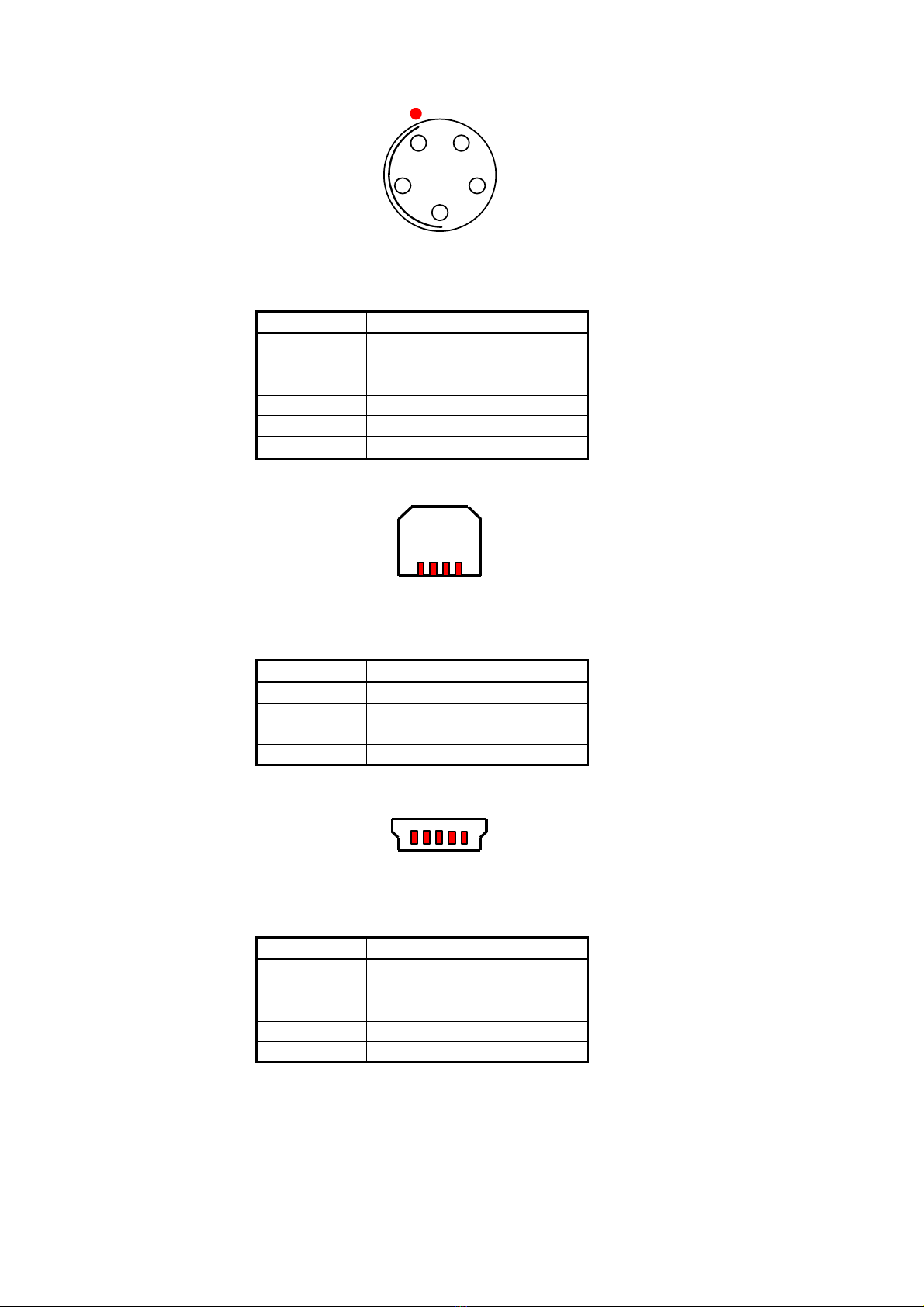
• Microphone connector FISHER DB102A054-130.
1
2
3
4
5
Fig. 2.1. Microphone connector external view.
Pin no. Signal
1 +13V
2 not connected
3 GND
4 not connected
5 signal input
screen case ground
• RS-232 connector Amphenol AMP-215875-1 to data transmission with PC.
1
4
Fig. 2.2. RS-232 connector – external view.
Pin no. Signal
1 GND
2 TxD
3 GND
4 RxD
• USB mini B connector Wurth Electronics 65100516121 to data transmission with PC.
1
5
Fig. 2.3. USB mini B connector – external view.
Pin no. Signal
1 VBUS
2 D-
3 D+
4 not connected
5 GND

11
• Charger connector RM650/1.3 DC-JACK with 1.3mm inner pin.
1
2
Fig. 2.4. Charger connector – external view.
Pin no. Signal
1 Positive supply terminal
2 Negative supply terminal
2.3. Default instrument settings
Default settings of DLM-101 after instrument turn-on are specified below:
• Frequency weighting A
• Time weighting FAST
2.4. Preparation of the instrument to operation
Connect the microphone to microphone connector. Take off microphone protecting cap. Place
windscreen on the microphone. Using windscreen is recommended regardless of weather
conditions because it gives the microphone additional protection against dust. Turn the
instrument on
Default instrument setup is specified in chapter 2.3. Now it is recommended to perform acoustic
calibration of the instrument as described in chapter 4.3.
After measurements completion turn the instrument off and place protecting cap on the
microphone.
3. OPERATION
All functions of the instrument are invoked using the keyboard but access to functions critical
for measurement is difficult. To activate this function selected key should be hold down for
about 1.5 second
Power of the instrument can be switched on or off by hold down power switch for about
1.5 second.
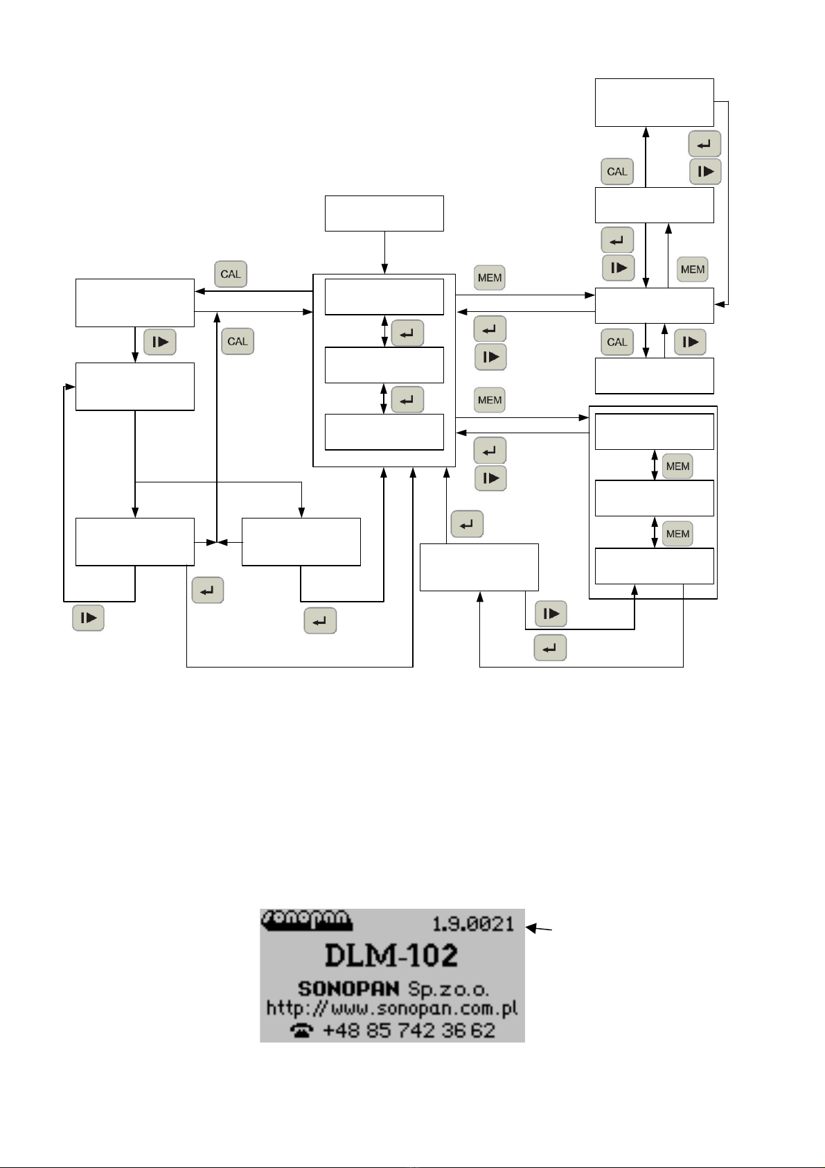
The scheme of transitions between menu screens is shown on Fig. 3.1. All menus are described in
details in this chapter.
12
Results 1
Results 2
any key
Calibration
ref. level
Calibration
measurement
Calibration
accept
Calibration
error
Repeat
OK Error
Accept
Cancel
Confirm
Cancel
1.5 sec
Reset cal.
factor
Results 3
Data plate
Save meas.
Load meas.
Delete meas.
1.5 sec
Delete all meas.
– confirm
Yes
No
History options
History data
History – del.
Delete all hist.
– confirm
Start/Stop
Back
1.5 sec
Last
Cancel
Yes
No
Fig. 3.1. The scheme of transitions between menu screens.
3.1. Instrument data plate
After turning the instrument on initial information is displayed on the screen. This information
contains instrument name firmware version and manufacturer data (name website phone).
After pressing any key results screen will be displayed. If no key is pressed instrument will
switch to the result screen automatically after 15 seconds.
If the internal battery of the instrument has been completely discharged the instrument may
not start immediately after the charger is connected - wait a few minutes then. After starting
before the data plate you will be prompted to enter the current date and time
Fig. 3.2. Instrument data plate.
firmware
version

13
3.2. Results
Results are updated once per second. When the measurement is stopped using START/STOP
key the measurement results are immediately available.
Fig. 3.3. Results screen 1.
Fig. 3.4. Results screen 2.
Fig. 3.5. Results screen 3.
Fig. 3.6. Results screen 3 – measurement history
log registration turned on.
On each results screen you can found:
• measurement time:
format hhh:mm:ss
• analogue level indicator
• battery gauge:
battery fully charged
battery charged in 75%
battery charged in 50%
battery charged in 25%
battery discharged
battery discharged automatic shutdown possible
• indicator of attached charger (if not attached this indicator is not visible):
charger is attached
• measurement status indicator:
measurement in progress
measurement stopped
waiting for instrument readiness to operation; the number displayed stands
for number of seconds remained to the end of waiting period
• time history registration indicator (if time history is turned off this indicator is not
visible):
time history registration turned on
• overload indicator (if there was no overload this indicator is not visible):
overload has occurred during last second
overload has occurred after measurement starting but not during last
second

14
• results:
result correct
result below measuring range (under-range)
no result.
frequency weighting change: A / C (only if the measurement is stopped)
hold down 3 seconds – language change: POLISH / ENGLISH
time weighting change: SLOW / FAST (only if the measurement is stopped)
START / STOP of measurement
current results screen change
hold down 1.5 second – clear current results (only if the measurement is stopped)
transition to measurement memory menu (only if the measurement is stopped)
hold down 1.5 second – transition to time history memory menu.
transition to date and time setup
hold down 1.5 second – transition to calibration menu (only if the measurement is
stopped).
WARNING! Changing frequency weighting or time weighting clear current measure results.
WARNING! Changing the language displays instrument data plate. After pressing any key,
results screen is shown back.
3.3. Date and time
You can use this menu to check the date and time currently set and change it. When you enter
edit mode set the hour minute second day month and year respectively passing to the next
item with the ENTER key. Pressing ENTER when the year is edited causes saving date and time
and to leave edit mode.
WARNING! It is not possible to set invalid date (e.g. 31-02-2017). In that case, press the
Cancel button and set the date again.
Fig. 3.7. Date and time.
Fig. 3.8. Date and time - edition.
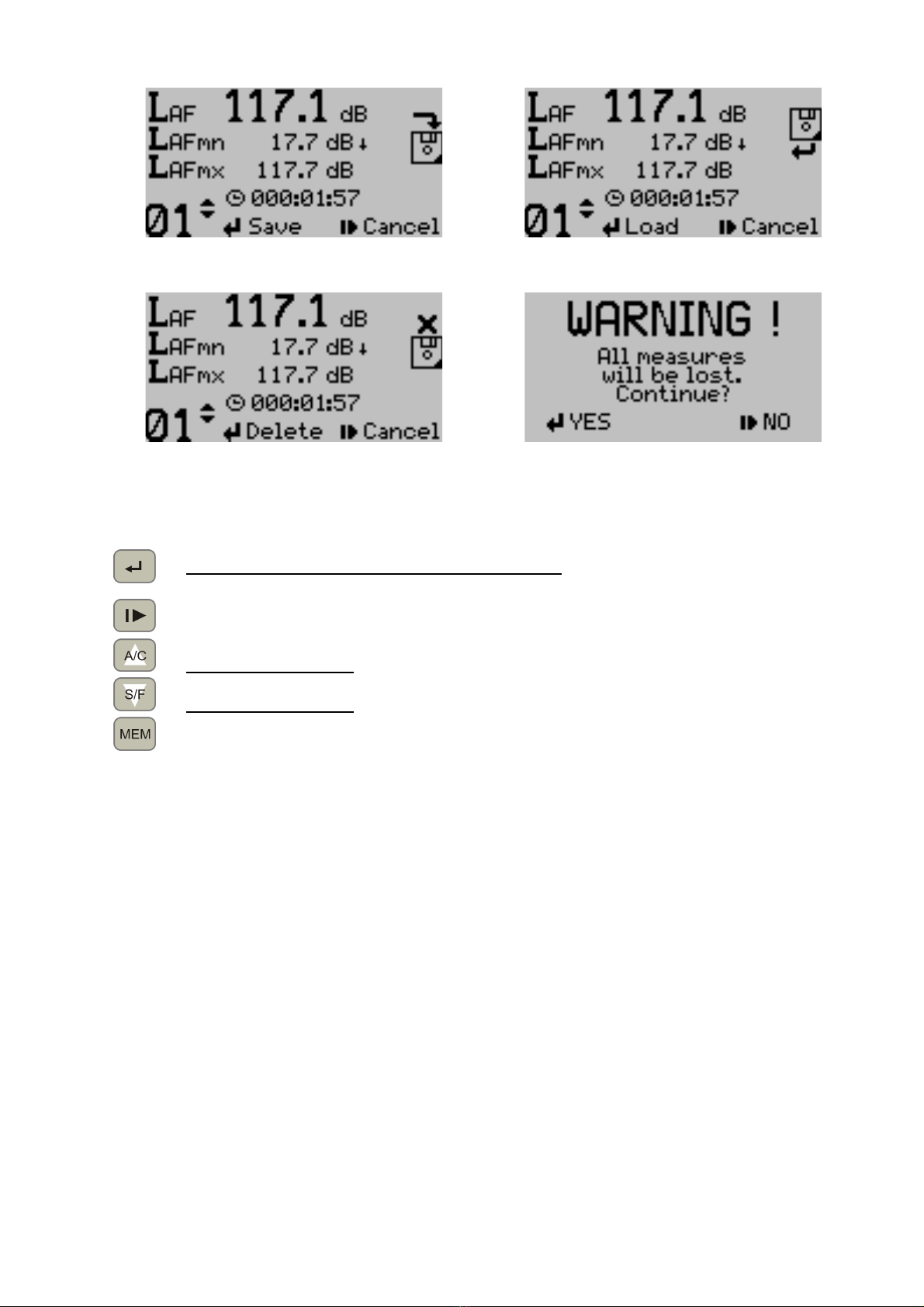
3.4. Measures memory
Using measures memory consists of three actions: save measure load measure and delete
measure. It is also possible to delete all measures but this requires additional confirmation.
15
Fig. 3. . Save measure to memory.
Fig. 3.10. Load measure from memory.
Fig. 3.11. Delete measure in memory.
Fig. 3.12. Delete all measures in memory –
confirmation.
save / load / delete measure confirmation
hold down 1.5 second on delete measure screen – delete all measures (with additional
confirmation)
cancel
select cell to save / load / delete – increase by 1
hold down 1.5 second – automatic repeat
select cell to save / load / delete – decrease by 1
hold down 1.5 second – automatic repeat
change the action: save / load / delete measure.
3.5. Time history memory
Time history registration means cyclic recording selected quantities into memory measured in
registration period. One to four quantities registration is possible: LXeq LXYmx LXYmn LCpk where X
stands for selected frequency weighting (A or C) and Y stands for selected time weighting (S -
SLOW or F - FAST).
The options screen displays the maximum registration time for selected combination of the
registration interval and number of quantities taking into account available free memory. In
addition you can set the recording interval (period) by selecting one of the predefined values:
100ms 1s 5s 10s 15s 30s 60s and enable or disable the automatic start option.
History registration starts when the measurement is started and ends when it is stopped or
when all available memory is full. If the autostart option is enabled then starting the next
measurement will also start time history recording.
It is possible to delete the last time history or all registered (this requires additional
confirmation).
The maximum time for recording history (with empty memory) is shown in the table below.

16
Time horizon (format: days – hours : minutes : seconds)
No of
quantities
100ms 1s 5s 10s 15s 30s 60s
1 000-
19:27:10
008-
02:31:44
040-
12:38:40
081-
01:17:20
121-
13:56:00
243-
03:52:00
486-
07:44:00
2 000-
11:40:18
004-
20:43:02
024-
07:35:10
048-
15:10:20
072-
22:45:30
145-
21:31:00
291-
19:02:00
3 000-
08:20:13
003-
11:22:10
017-
08:50:50
034-
17:41:40
052-
02:32:30
104-
05:05:00
208-
10:10:00
4 000-
06:29:03
002-
16:50:34
013-
12:12:50
027-
00:25:40
040-
12:38:30
081-
01:17:00
162-
02:34:00
Fig. 3.13. Time history – options.
Fig. 3.14. Time history – selecting quantities.
Fig. 3.15. Time history – delete.
Fig. 3.16. Delete all time histories – confirmation.
Start / Stop time history registration
return to the previous screen
transition to selecting quantities to register
selecting registered quantity
selecting registered quantity
transition to delete time history menu.
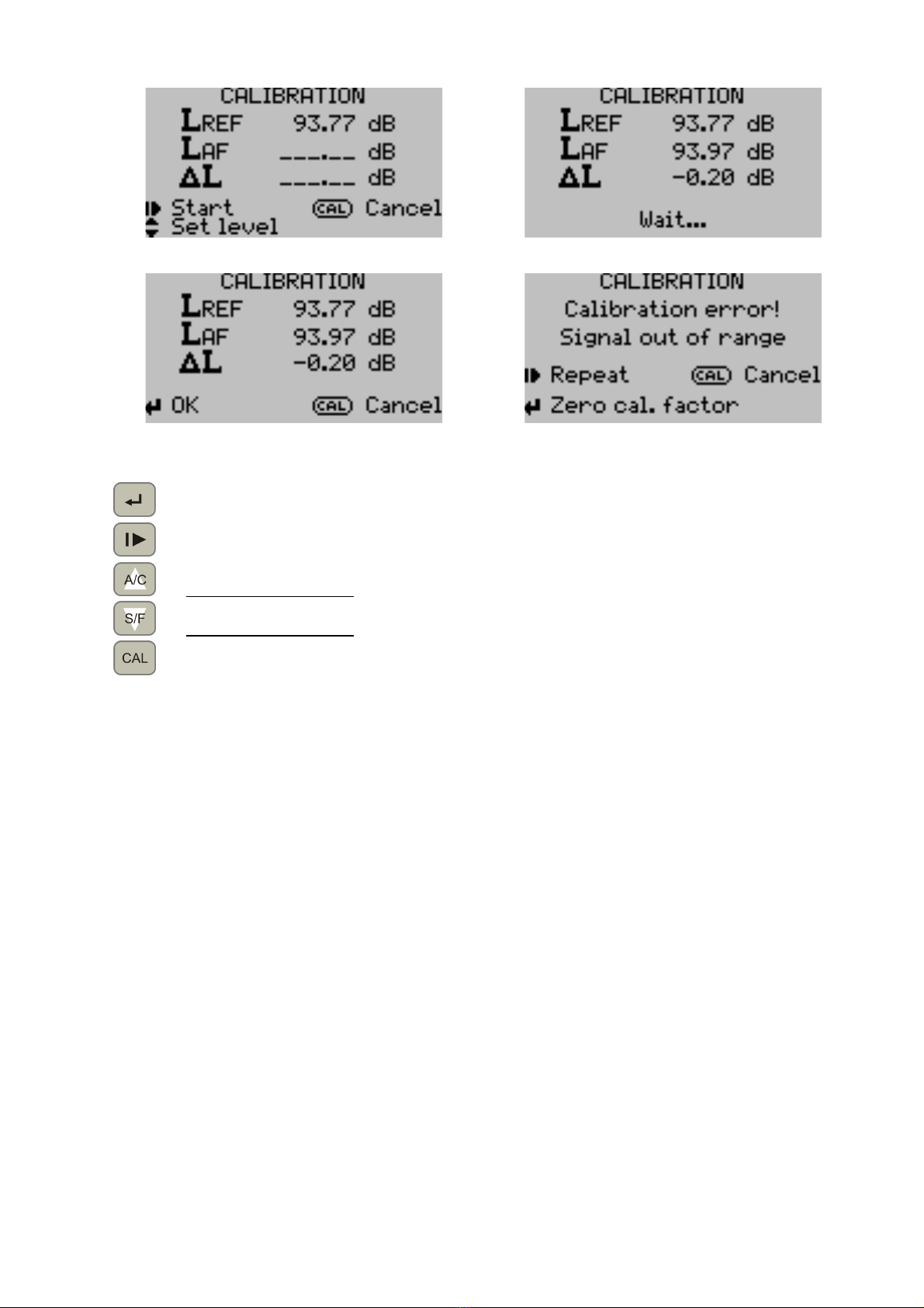
3.6. Calibration
Calibration consists of three phases:
• setting reference level – detailed description of the calibration is in chapter 4.3
• coupling acoustic calibrator and running the measurement
• reading the result or error message and accepting it.
Menu screens of each phase are presented below.
17
Fig. 3.17. Calibration – setting reference level.
Fig. 3.18. Calibration – measurement in progress.
Fig. 3.1 . Calibration – accept the result.
Fig. 3.20. Calibration – error message.
accept the result of the calibration / zero calibration factor if calibration error
start / repeat the measure
set reference level – increase by 0.01dB
hold down 1.5 second – automatic repeat
set reference level – decrease by 0.01dB
hold down 1.5 second – automatic repeat
abort calibration procedure reject results and back to the results screen.
4. RECOMENDATIONS FOR INSTRUMENT USE
During instrument use following recommendations should be strictly observed:
• perform all connection changes (connecting or disconnecting of microphone) only when
the instrument is turned off; making these changes when the instrument is turned on
can lead to instrument damage
• protect the microphone against mechanical shocks dust moisture and strong gusts of
wind (use windscreen!).
4.1. Recommendations for correct performing of measurements
Fasten the instrument (or its microphone) to its supporting stand and ensure you are located at
a distance (from the instrument or its microphone) assuring to avoid sound field disturbance.
The measurement range should be chosen so that the meter does not indicate over-range or
under-range condition of the measurement circuit. If the indicated value is less than the lower
limit of the meter's linearity range the correction should be subtracted from the measurement
result. This correction is calculated on the basis of the self-generated noise level read from
calibration certificate using the formula::
(
)
LsLw
L⋅⋅ −⋅= 1.01.0 1010log10
where:
L corrected sound level
Lw sound level read from the meter
Ls self-generated noise level

18
Do not perform measurements if the ambient temperature and humidity combination can lead
to vapor condensation in the microphone.
4.2. Internal battery
The instrument is normally operated with internal battery supply. To charge the battery connect
the charger. Attaching the charger is indicated by lighting LED located near charger connector
and displaying icon on results screen also there is a battery gauge displayed on results screen.
Battery charging in progress is indicated by pulsing LED. If the LED continuously lit it means that
battery is fully charged.
As far as possible before charging the internal battery have to be fully discharged (to
automatically switch off the instrument) - avoid the situation when the battery is often
recharged a little bit beacause it reduces its durability. Continuous operation with connected
charger is possible..
WARNING! If the instrument is not used for more than two months, the battery should be
recharged. This is necessary because of self-discharge of the battery.
WARNING! The battery is charged regardless of whether the instrument is turned on or off!
4.3. Calibration of the instrument
Correct measurement can be performed only when calibrated instrument is used.
Recommended sound calibrator for DLM-102 sound level meter is SONOPAN KA-10 acoustic
calibrator. This device produces calibrated sound signal of 94 dB nominal sound pressure level
and 1000 Hz nominal frequency. Another sound calibrator of class 2 or better producing signal
of nominal sound pressure level and frequency equivalent to KA-10 sound calibrator can be also
used for calibration.
To perform calibration of the instrument correctly:
• enter calibration mode (see chapter 3)
• calculate and set reference level:
Lref = Lkal + ∆Lff
Lkal acoustic calibrator sound pressure level read from its calibration certificate
∆Lff free field correction for ¼” microphone equal to 0 00dB.
• couple calibrator with the microphone and turn it on.
• start the calibration procedure.
• calibration will be conducted automatically after a moment you will get the result to
accept.
• if an error message appears remove the cause of an error and repeat the measurement.
• after accepting calibration result turn off and decouple the calibrator.
• meter is ready to measurement.
WARNING! During calibration the instrument together with the calibrator shall not be
exposed to noise higher than nominal sound pressure level of sound calibrator in use or
ground vibration.

19
Calibration error messages description:
Message Possible cause
Signal out of range
- calibrator turned off
- calibrator poorly coupled
- invalid reference level
- broken microphone.
Unstable reading
- too high background noise level
- strong ground vibrations
- broken calibrator
- broken microphone.
Unknown error - unknown contact service.
4.4. Warranty
SONOPAN grants the warranty on following stipulations:
• no remains of changes corrections crossing-out etc. are found on Warranty Card
• the instrument shall be used according to manufacturer Instruction Manual
• the warranty becomes void if instrument repairs or modifications are undertaken by
unauthorized persons.
SONOPAN warrants this instrument:
• to be fulfilling the specifications given in Instruction Manual
• to be working correctly for 12 months from purchase date in 24 months from date the
instrument was produced.
Not covered by this warranty:
• damages resulting from instrument transportation (provided no clear neglects of
manufacturer have been stated)
• mechanical damages through the fault of the purchaser
• internal damages through the fault of the purchaser.
The purchaser is entitled to warranty claim only when instrument dealer does not meet his
obligations resulting from this warranty.
4.4.1. Complaint instructions for the purchaser:
• contact SONOPAN and specify the cause of complaint Warranty Card number date and
place of purchase and date the instrument was produced
• after complaint receipt is confirmed send the instrument with Warranty Card included to
SONOPAN by freight company
• if SONOPAN service find instrument damage to be not covered by warranty or warranty
conditions to be not fulfilled then the purchaser is obliged to cover service and
transport costs as specified in the bill made out by SONOPAN
• the costs specified above are covered by SONOPAN if the complaint is accepted.
4.5. Maintenance and repair
DLM-102 sound level meter requires no special maintenance treatments.
All repairs of the instrument are performed by the manufacturer.
4.6. Firmware
User has no ability to update install delete firmware of the meter. Firmware version is displayed
on instrument data plate detailed description is presented in chapter Błąd! Nie można
odnaleźć źródła odsyłacza..

20
5. CE MARKING AND CONFORMANCE TO EU COUNCIL
DIRECTIVES
The product described in this instruction conforms to following EU Council Directives:
2004/108/EC Electromagnetic compatibility.
The conformance to above-mentioned
requirements is confirmed by CE mark.
This product cannot be thrown away with household waste. Deposit the
product in an authorized electrical and electronic waste collection area for
recycling. Contact local Municipal Bureau or nearest waste disposal company
to get more detailed information.
Table of contents
Other SONOPAN Measuring Instrument manuals


Popular Measuring Instrument manuals by other brands


Wacom
Wacom SD-210L user manual

Panametrics
Panametrics DigitalFlow GS868 Programming manual

DOSER Messtechnik
DOSER Messtechnik DM7 operating instructions

Xylem
Xylem FLYGT CCD 301 Installation, operation and maintenance manual

Danfoss
Danfoss SonoSelect installation guide

BRUEL & KJAER
BRUEL & KJAER Matron 3 user manual

TX Testing Instruments
TX Testing Instruments ED-400 user manual

Endress+Hauser
Endress+Hauser Stamolys CA71NO operating instructions

Balluff
Balluff BFT Series user guide

Pro-dig
Pro-dig Intelli-Tork H200 instruction manual

Precision Medical
Precision Medical 3MFA1001 quick start guide

GHM
GHM Delta OHM LPPYRA13 operating manual