SONOPAN L-100 User manual

LUXMETER L-100
INSTRUCTION MANUAL
PPUH SONOPAN Sp. z o.o.
Poland, 15-950 Bialystok, ul. Ciolkowskiego 2/2
tel./fax:+48 (85) 742 36 62
http://www.sonopan.com.pl

–
2 –
CONTENTS:
1. INSTRUMENT CHARACTERISTICS ...............................................................................................4
1.1. Technical specification ................................................................................................................4
1.2. Measuring probe ..........................................................................................................................5
1.3. Control unit..................................................................................................................................5
2. ACCESSORIES ...................................................................................................................................5
2.1. Basic accessories..........................................................................................................................5
2.2. Additional accessories .................................................................................................................6
3. GENERAL VIEW ................................................................................................................................6
4. RESULTS PANEL...............................................................................................................................6
4.1. Measure window..........................................................................................................................7
4.1.1. Measured quantity value format..............................................................................................7
4.2. Measured value logarithmic bar ..................................................................................................8
4.3. Status bar .....................................................................................................................................8
4.3.1. Measurement range field .........................................................................................................8
4.3.2. Measure type field ...................................................................................................................8
4.3.3. Change range control field ......................................................................................................8
4.3.4. Statistics field ..........................................................................................................................8
4.3.5. Memory field...........................................................................................................................8
4.3.6. Battery indicator field..............................................................................................................8
4.3.7. Alarm field ..............................................................................................................................9
4.3.8. Date/time field.........................................................................................................................9
5. OPERATION .......................................................................................................................................9
5.1. Menu............................................................................................................................................9
5.1.1. Menu MODE...........................................................................................................................9
5.1.1.1. Single measure................................................................................................................9
5.1.1.2. Continuous measure........................................................................................................9
5.1.1.3. Relative measure.............................................................................................................9
5.1.1.4. Integration.....................................................................................................................10
5.1.1.5. Integration-clear............................................................................................................10
5.1.1.6. Statistics........................................................................................................................10
5.1.2. Menu SETUP ........................................................................................................................10
5.1.2.1. Autorange .....................................................................................................................11
5.1.2.2. Zero setting ...................................................................................................................11
5.1.2.3. Calibration... .................................................................................................................11
5.1.2.4. Luminance ....................................................................................................................11
5.1.2.5. Backlight.......................................................................................................................12
5.1.2.6. More..............................................................................................................................12
5.1.3. MEMORY.............................................................................................................................13
5.1.3.1. Save measure... .............................................................................................................13
5.1.3.2. Load measure................................................................................................................14
5.1.3.3. Clear last .......................................................................................................................14
5.1.3.4. Clear all.........................................................................................................................14
5.1.3.5. Autosave... ....................................................................................................................14
5.1.3.6. Send to PC... .................................................................................................................15
5.2. Turning on the instrument..........................................................................................................15
5.3. Selecting measurement range ....................................................................................................16
5.4. Measuring ..................................................................................................................................16
5.4.1. Single measure ......................................................................................................................16
5.4.2. Continuous measure ..............................................................................................................16
5.4.3. Relative measure ...................................................................................................................16
5.4.4. Integrating .............................................................................................................................16
5.4.5. Statistics.................................................................................................................................16
5.5. Measures memory......................................................................................................................17
5.5.1. Working with external memory module................................................................................17
5.6. Working with luminance measure adapter ................................................................................17
5.7. Working without measure probe................................................................................................18
5.8. Turning off the instrument.........................................................................................................18

–
3 –
6. COMMUNICATION WITH PC........................................................................................................18
6.1. Transmission protocol................................................................................................................18
6.2. Automatic power on...................................................................................................................18
6.3. PC software................................................................................................................................19
7. POWER SUPPLY ..............................................................................................................................19
7.1. Control of battery supply. ..........................................................................................................19
7.2. Automatic power off..................................................................................................................19
8. RECOMMENDATIONS FOR INSTRUMENT USE........................................................................19
9. WARRANTY AND REPAIRS..........................................................................................................20
10. CE MARKING AND CONFORMANCE TO EU COUCIL DIRECTIVES.................................20
11. APPENDIX A: Photometric probe G.L-100.................................................................................21
12. APPENDIX B: Luminance measure adapter PL1.-RF100 ...........................................................22

–
4 –
1. INSTRUMENT CHARACTERISTICS
Luxmeter L-100 belongs to the family of RF-1xx devices (where xx is numerical designation). De-
vice structure is based on concept of separation device function onto probe with is complete meter and
user control unit which role is link user control device with probe. This concept of device allows operat-
ing with many probes with can have different metrological function. Under notion of metrological func-
tion includes here: detector spectral characteristics, number of measure ranges, dynamic range, unit of
physical quantity. Type of measure probe decides about complete measurement device function, so it can
be photometer or radiometer with arbitrarily defined spectral sensitivity. Control unit has defined list of
probes together it can operate and it has predefined maximal firmware version of probe with it can oper-
ate. It allows in easy way to evolve into both device types with backward compatibility into older ver-
sions.
Luxmeter L-100 is designed to work with measure probe type G.L-100. Radiometer-photometer
RF-100 with G.L-100 probe implements luxmeter function too.
Luxmeter L-100 fulfill recommendations of International Commission On Illumination (CIE),
published in publication no. 69-1987: „Methods of characterizing illuminance meters and luminance me-
ters: Performance, characteristics and specifications”.
Device was approved by Polish Central Office of Measures (decision no. RP T 02 196). Luxmeter
L-100 is designed for measurement illuminance in range from 0.001 lx to 300 000 lx, but after installing
proper adapter - for measurement luminance. There are three kinds of luminance adapters with different
field apertures: 1°, 3°, 10°.
Luxmeter L-100 fulfills requirements of EMC standards:
EN 61326 „Electrical equipment for measurement, control and laboratory use. EMC re-
quirements ”.
EN 61000-6-2 „Electromagnetic compatibility (EMC). Generic standards. Immunity standard
for industrial environments ”
EN 61000-6-3 „Electromagnetic compatibility (EMC). Generic standards. Emission standard for
residential, commercial and light-industrial environments ”
1.1. Technical specification
• Accuracy class: A (CIE)
• Accuracy: ≤2.5% ±1LSB
• Spectral matching: f1’≤2% (CIE)
• Cosine correction matching: f2≤1.5% (CIE)
• Detector: Silicon photodiode V(λ) (CIE standard photometric observer)
spectral filtered and cosine corrected
• Measure ranges:
Luxmeter Luminance meter
L [cd/m2]
E [lx]
1° 3° 10°
0.001 ÷ 30 0.1 ÷ 12k 0.01 ÷ 1.2k 0.001 ÷ 120
0.1 ÷ 3000 10 ÷ 1.2M 1 ÷ 120k 0.1 ÷ 12k
10 ÷ 300 000 1k ÷ 120M 100 ÷ 12M 10 ÷ 1.2M
• Display: LCD 128×64,
• Supply: Battery 9V (IEC: 6LR61)
• Dimensions: 152 × 83 × 33 mm
• Operating temperature: 0 ÷ 40ºC
• Operating humidity: ≤80%
Main features of instrument:
• Manual or automatic measurement range control.
• Four different measure modes: single, continuous, relative to set reference, integration.
• Statistical calculations: average, minimum, maximum, min/average, min/max.
–
5 –
• Manual or automatic adding measurement to statistics.
• Measure memory: 512 cells with user comments.
• External memory module (511 cells).
• Viewing measures saved in memory.
• Continuation of measurement saved in memory.
• Manual or automatic writing measures to memory.
• Zero setting measure probe (detector dark current).
• Automatic zero function.
• Measurement probe calibration system.
• RS232C communication port.
• Remote switching on/off through RS-232C interface.
• Calendar and real time clock with alarm function.
• Battery gauge.
• Auto power-off function.
• LCD backlight.
The device user options are available through expandable menu lists visible at graphic display.
Luxmeter L-100 consists of two cooperate units: measuring probe and control unit.
1.2. Measuring probe
Measuring probe G.L-100 is complete photometer which includes:
• Spectral and cosine corrected detector.
• Analog to digital converter.
• Zero setting system.
• Auto zero setting system.
• Automatic measure range control.
• Calibration value register.
• Control unit communication interface.
0,0
0,1
0,2
0,3
0,4
0,5
0,6
0,7
0,8
0,9
1,0
380
400
420
440
460
480
500
520
540
560
580
600
620
640
660
680
700
720
740
760
λ
[nm]
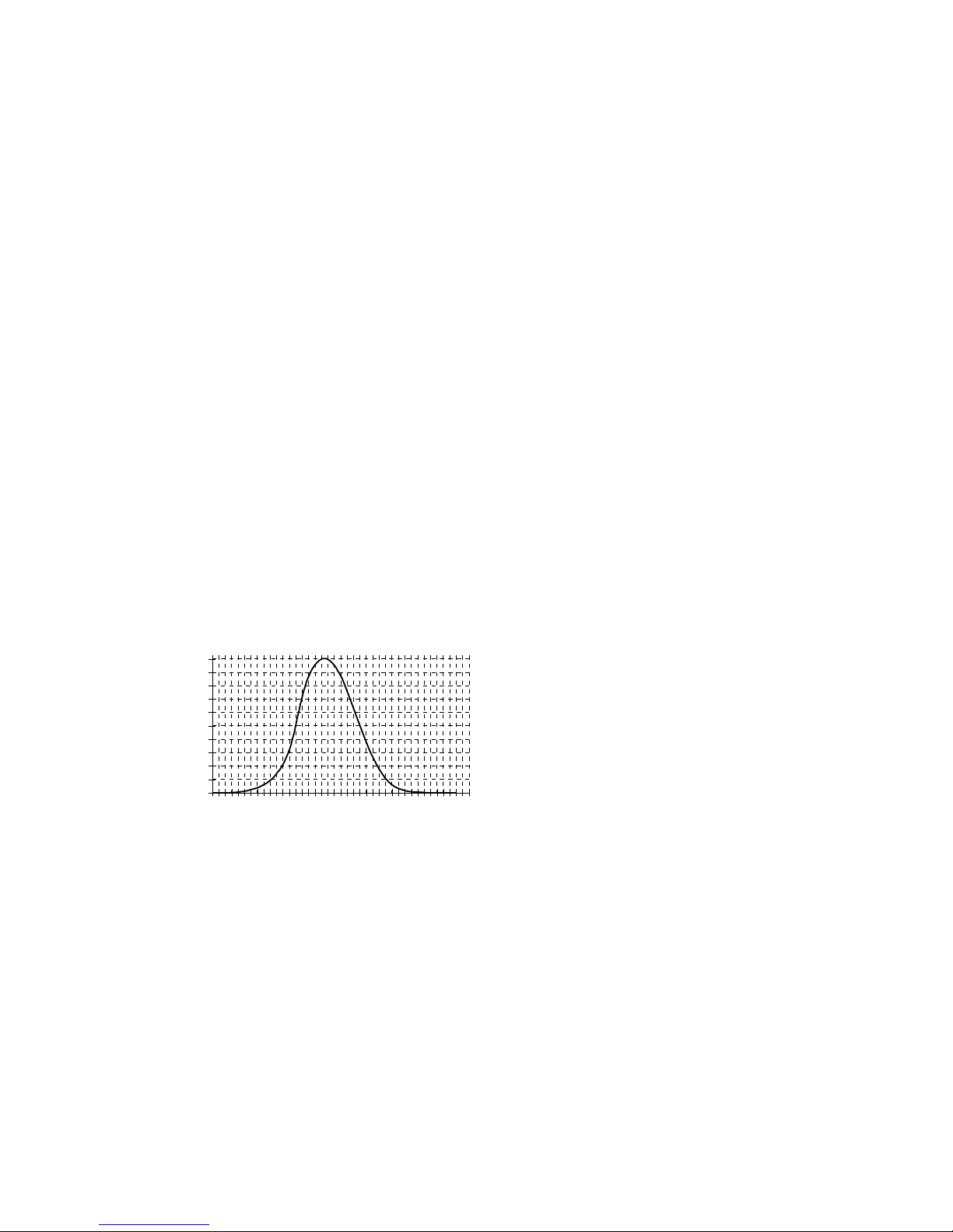
Fig. 1. Relative visible spectrum response of measure probe type G.L 100
1.3. Control unit
Control unit provides:
• Communication with measurement probe.
• Visualization measured results.
• Human machine interface.
• Communication with PC.
2. ACCESSORIES
2.1. Basic accessories
• 9V battery.

–
6 –
• RF-1xx PC software.
• RS232C interface cable.
• Instruction manual.
2.2. Additional accessories
• Luminance measure adapter PL1.RF-100 (field aperture 1°).
• External memory module MP32.RF-100 (511 cells).
• Luxmeter calibrator KF-10.
• Photometric probe handle.
• Carrying case.
There are profiled soft nests assigned for placing accessories inside carrying case. They provide proper
storage and transport conditions that don't expose content on mechanical damages.
3. GENERAL VIEW
–
P
D
Y
M
A
$ +
S V
G J
@
Q
E
Z
N
B
% !
T W
H K
#
R
F
/
O
C
& ?
U X
I L
9
5
1
8
4
0
6 7
2 3
LUXMETER L-100
MODE
SETUP
h
i
d
d
e
n
c
a
l
i
b
r
a
t
e
b
u
t
t
o
n
b
a
c
k
l
i
g
h
t
b
u
t
t
o
n
measure probe socket
ext. power supply / PC socket
display
keyboard
alphanumeric keyboard
ESC
external memory socket
Fig. 2. L-100 luxmeter general view.
4. RESULTS PANEL
Results panel is main window of the meter. All bookmarks are hidden and there is no displayed message
on the screen. Results panel consists of measure window, logarithmic bar of measured value and status
bar.
–
7 –
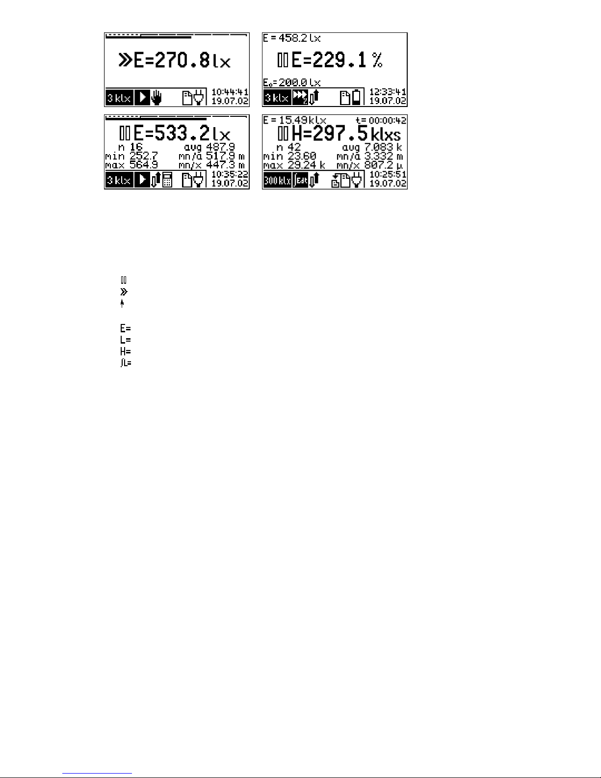
Fig. 3. Results panel view for illuminance, relative measurement, statistics and integration mode
4.1. Measure window
Measure window includes:
• measure state indicator:
pause,
run,
• range overflow indicator,
• measured quantity symbol:
illuminance
luminance,
luminous exposure (time integral of the illuminance),
time integral of the luminance,
• measured quantity value,
• measured quantity unit.
Besides:
for relative measurement mode: actual measured value (E) and reference value (E0) ,
for integral measurement mode: actual measured value (E) and integration time (t) in format
hours:minutes:seconds,
for statistics and integration mode: statistics field including: number of measures (n), minimum (min),
maximum (max), average (avg), minimum to average ratio (mn/a),
minimum to maximum ratio (mn/x).
In measured quantity unit field, before basic unit, multiplier can be displayed. Measured values displayed
in statistic field do not includes designation of basic unit. Only metric prefix corresponding to multipliers
are displayed:
• f (femto) = ×10-15
• p (pico) = ×10-12
• n (nano) = ×10-9
• µ (micro) = ×10-6
• m (mili) = ×10-3
• k (kilo) = ×103
• M (mega) = ×106
• G (giga) = ×1012
• T (tera) = ×1015
• P (peta) = ×1018
4.1.1. Measured quantity value format
Measured quantity value is displayed in measure window with fixed resolution, corresponding to set
measure range. In case when measure value is greater then 9999×LSB (where LSB is weight of less sig-
nificant bit), there is a clipping of showed number to four most significant digits. Position of decimal
point and unit multiplier are set to present result with best precision.
–
8 –
4.2. Measured value logarithmic bar
Measured value bar: is placed in upper part of the result screen. Bar is
displayed during illumination measure without relative measure or statistics option selected. It includes
scale that covers whole measuring range and strip of fulfillment. Doted part of scale covers lower range.
If strip of fulfillment is in this area it signifies, that measurement is possible with greater resolution on
lower range. Indicator is not refreshed during return from MENU to result panel.
4.3. Status bar
Current setup is displayed in lower part of meter’s screen. This status bar is divided into: measurement
range field, measure type field, change range control field, statistics field, memory field, battery indicator
field, alarm field, date/time field.
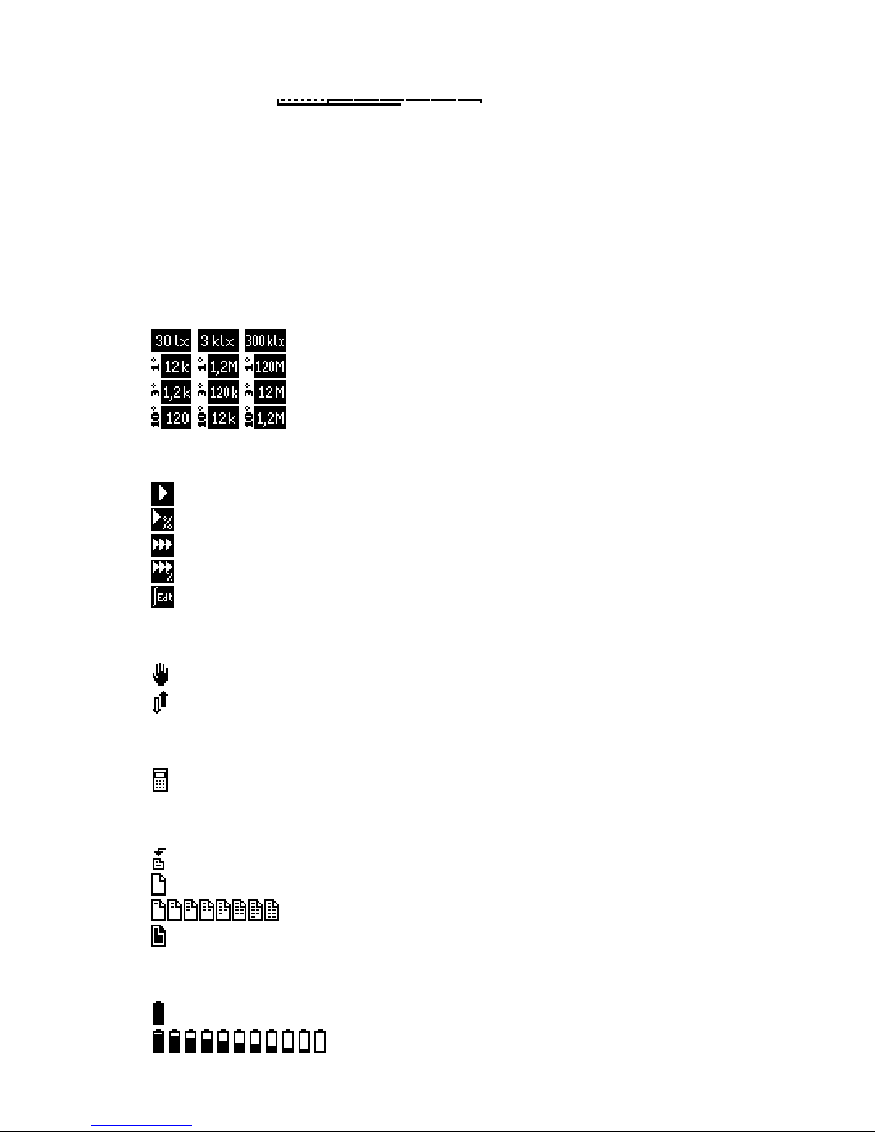
4.3.1. Measurement range field
selected measurement range (illuminance),
selected measurement range (luminance with 1° field aperture [cd/m2]),
selected measurement range (luminance with 3° field aperture [cd/m2]),
selected measurement range (luminance with 10° field aperture [cd/m2]),
4.3.2. Measure type field
single measure,
relative single measure,
continuous measure,
relative continuous measure,
integration.
4.3.3. Change range control field
manual measurement range control (only for single measure mode),
automatic measurement range control.
4.3.4. Statistics field
automatic adding measure to statistics.
4.3.5. Memory field
automatic save measure to memory,
Memory is empty,
Memory is partially full,
Memory is full.
4.3.6. Battery indicator field
Battery is full,
Battery is partially empty,

–
9 –
Battery is empty,
4.3.7. Alarm field
Alarm is active.
4.3.8. Date/time field
Current date and time is shown in lower right corner of a display. In case
when viewing measures from memory, this field displays date and time of
saved measure.
5. OPERATION
5.1. Menu
Menu contains three bookmarks: MODE, SETUP, MEMORY, which are selected through buttons:
. All bookmarks contains list of available options. User can change setup option by
changing the position of pointer (option displayed in negative) by arrows: and apply the setup value
by key . Menu items which have sub-menus are ended with three dots (expandable menu). Instrument
memorize last position of menu pointer.
Canceling is available using key .
Actual selected options are signalized on the list by checkout .
The messages that are shown during operation can be deleted by keys: or . Changing instru-
ment setup can be only made in pause mode. All setup values and positions of pointers in menus are
memorized and will be restored after power on.
5.1.1. Menu MODE
Instrument can operate in one of three modes:
−
−−
−single measure,
−
−−
−continuous measure,
−
−−
−integrating.
Additionally, for single or continuous measure relative measure option is provided (on/off type).
Fig. 4. Menu MODE with selected continuous measure option.
5.1.1.1. Single measure
Function: turns on single measure mode, other options stay unchanged.
5.1.1.2. Continuous measure
Function: turns on continuous measure mode, also turns on automatic measurement range control.
5.1.1.3. Relative measure
Function: turns on/off relative measure option.

–
10 –
After turning on this option, new window for setup reference value opens. Window contains last meas-
ured value by default for reference:
Edit can be made by passing numeric values directly from alphanumerical keyboard. Position of cursor
can be modified by key . Keys change multiplication factor of unit. Approving reference value
can be made by key . After that instrument change measurement range control to automatic. If that
option was selected during integrating mode, single measure mode is selected by the instrument.
5.1.1.4. Integration
Function: turns on integration mode.
Instrument loads last measures values after switching to this mode, so continuation of last integral meas-
urement is possible. Result value of actual illuminance is rewritten from last single or continuous meas-
ure. After leaving integrating mode (switching to single, continuous or relative measure), in the result
field instrument displays last measured value of illuminance during integral operation mode.
5.1.1.5. Integration-clear
Function: Clears measured integrated value and it's related statistics.
Instrument displays notice window: . After selecting YES and approving it by key me-
ter deletes measured integrated value and it's related statistic values.
5.1.1.6. Statistics...
Function: displays statistics sub menu:
−
−−
−Add measure - adding last measure to statistics.
−
−−
−Clear all - delete (after approving the notice window) statistics .
−
−−
−Auto add - appending data to statistics after every measure (on/off).
Statistic option only concern single and continuous measure. In integrating mode instrument make inde-
pendent statistical calculations.
5.1.2. Menu SETUP
Fig. 5. Menu SETUP menu with selected options: automatic measurement range control (Autorange) and display
backlight on.

–
11 –
5.1.2.1. Autorange
Function: turns on/off automatic measurement range control.
Turning off this option is equal to set manual measurement range control. In this case single measure
mode will be set automatically.
5.1.2.2. Zero setting
Function: compensates photo detector dark current.
WARNING! Zero setting can be made only after covering measure probe. If measure probe at
zero setting process is not covered, instrument may work improperly.
The meter will remind about covering measure probe, and after pressing key, zeroing process will be
started..
Zero setting process is done on all measurement ranges. Values of zero setting are saved in internal regis-
ters of measure probe.
5.1.2.3. Calibration...
Function: stores calibration factor in measure probe.
WARNING! Calibration should be made only by authorized personnel of the calibration labora-
tory, during instrument calibration process. In other case, instrument indications
may be incorrect.
Calibration can be done on any measurement range for value about 3/4 measurement range.
After selecting Calibration from SETUP menu, new edit window will be opened:
Value editing is allowed by inputting values from alphanumerical keyboard. Position of cursor can be
changed by key . Keys change multiplication factor of unit. Approving calibration value can be
made by key „Calibration” available through hole on the left side of control unit (Fig. 2). If inputted
value does not fit instrument criteria, meter will generate one of the following error messages:
New calibration factor is stored in internal registers of measure probe. From main window of instrument
last and actual calibration factor can be viewed only in the same form that is saved in internal probe regis-
ter:
The value of calibration factor may include in range: 0.5÷1.0. In internal memory probe format that value
equals range: 4194304÷8388607.
Calibration can be done also in luminance mode. The Calibration factor is only one and it equal concerns
illuminance and luminance measurements. This can be done because control unit allows only proper dis-
play and calculation of various physical values.
5.1.2.4. Luminance
Function: turns on/off luminance measure mode.

–
12 –
It is necessary to connect (or disconnect) proper luminance measure adapter. Type of used adapter can be
chosen from expandable luminance menu:
Luminance mode can be set only for probes that are compatible with this mode. In other case instrument
does not allow to setup that option (includes RF-100 and probes not equal to G.L-100).
For luminance option, all types of instrument operations are available. Besides all setup option, integral
values and statistics are memorized. That option allows to continue measures when switching from illu-
minance to luminance mode and vice versa.
5.1.2.5. Backlight
Function: turns on/off display backlight.
Display backlight increase contrast of LCD display, through that increase readability of the screen, but
when it's on, it decrease battery life time. On battery, backlight power is reduced to extend battery life and
it’s visible in dark rooms only. On external DC adaptor, backlight is visible at normal illumination. Using
backlight increase power consumption about 25%. By default, display backlight is turned off.
Backlight can be turned on for a moment by using key placed on left side of lateral control unit (Fig. 2).
5.1.2.6. More...
Function: displays sub menu for system setup options:
−
−−
−Date-Time... - real time clock setup. New windows will open sequentially:
Setup values is done by the alphanumeric keyboard keys. Position of cursor can be
changed in right direction by keys , and in left direction by key . Approv-
ing setup values is done by key .
−
−−
−Alarm... - turning on/off alarm. This option can be used in example to remind about date of
calibration. When alarm is active (signalized by icon in status bar: ), during
startup of instrument alarm message will appear, if date will be equal or greater
than setup alarm date value. After switching alarm option on new windows will
open sequentially:

–
13 –
Editing date value is done like edit process of real time clock setup. During alarm
message edit process, directly from keyboard alphanumeric keys are available base
characters (digits, dot and space). Additionally with all keys, user can input three
different characters that are placed at left part of the key. Switching through differ-
ent key functions is done by using menu keys: , that background
color is same as input special characters. So, to enter character from upper row of
special characters, user must press key , from middle row – key and
from bottom row – key , before pressing keyboard alphanumeric key.
If menu key was used again it cause switching to entering base characters mode.
Shape of cursor decides about selected sort of input character: - base characters,
- upper row characters, - middle row characters, - bottom row characters.
Cursor position can be shift right by keys: , and shift left by key . Ap-
proving setup value can be done by key .
−
−−
−Auto off... - inactive time setup for auto off mode. After selecting, new window will appear:
Keyboard key shift pointer to previous position, to next position, and
shift among columns. Approving setup value can be done by key . This setup
window sets time interval that must elapse from last key press to automatic turning
off the instrument. This time is counted only if instrument is in PAUSE mode.
Automatic power off is used for increase battery life time.
−
−−
−RS 232... - RS 232 data transfer parameters setup. After selecting, new window will appear:
Menu contains, in sequence: baud rate, parity control, number of data bits and
number of stop bits. As can be seen, user can only change baud rate – the rest of
transmission parameters are the same for all options. Selection can be done by keys
and approving setup values can be done by key .
−
−−
−Service mode... - This option should be used only by manufacturer, in production process. It should
not be used by user.
5.1.3. MEMORY
Fig. 6. Menu MEMORY with autosave option turned on.
5.1.3.1. Save measure...
Function: saves last measure to memory.
–
14 –
After selecting, new window with cell number and comment will appear (max 512 cells for internal
memory and 511 for external memory):
Comment editing can be done just like editing alarm comment in menu SETUP. Approving setup value
can be done by key .
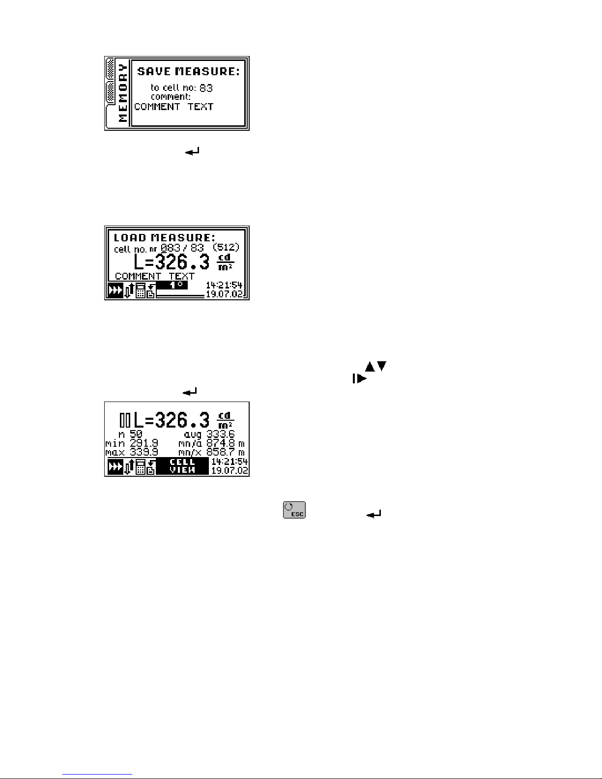
5.1.3.2. Load measure...
Function: browses memory content.
After selecting, new window with measure saved in cell will appear:
Fig. 7. Window with measure saved in cell.
In this window, instrument displays: number of current cell, number of occupied cell, measured value
with unit, user comment, instrument setup during measure, date and time of measure.
By default, instrument displays last saved cell. Editing number of browsing cell is done by keyboard al-
phanumeric keys, by entering suitable cell number or by keys increasing or decreasing number of
actually selected cell. Cursor position change is done by key .
After pushing key new window with data stored in selected cell (data explorer window) will appear:
Fig. 8. Data explorer window.
User can return to cell list by pushing key , pushing key will load content of displayed cell to
measure window of the instrument. Measure options and saved instrument setup is set in the instrument.
This option allows in easy way to continue saved measure. However meter forbids stored luminance
measure when instrument is not in luminance measure mode. Also meter forbids stored illuminance
measure when instrument is in luminance mode. Control unit forbids stored measure that was made with
different probe that actually is connected to the instrument (concerns RF-100).
5.1.3.3. Clear last
Function: clears content of last saved memory cell (after approving).
5.1.3.4. Clear all
Function: clears content of all memory cells (after approving).
5.1.3.5. Autosave...
Function: turns on/off automatic save measures to memory.
After selecting, new window to select auto save time will appear :

–
15 –
Selecting predefined time interval is done by keys and approve by key . After that, new
window witch allows user to edit comment, will appear. The comment is the same for all automatically
saved measurements:
Process of comment editing is the same, as in case of editing alarm comment.
With auto save option turned on, instrument will switch to continuous measure mode. Instrument firm-
ware does not allow switching to single measure mode or turning off automatic measurement range con-
trol while auto save option is turned on. After running measure, instrument will save measurements with
predefined time interval. During measure, instrument signalize auto save by blinking icon and by mem-
ory auto save icon on status bar. After filling of all available memory cells, measure process will be
stopped and “memory full” message will be displayed.
5.1.3.6. Send to PC...
Function: sends memory content to PC.
After selecting, new window will appear:
Transmission will start after pressing key . During data transmission, progress is displayed. Transmis-
sion process can be broken through keyboard key .
5.2. Turning on the instrument
To power on the instrument, user must press key . First, data plate with manufacturer data and
firmware version is displayed:
Fig. 9. L-100 luxmeter data plat.e
In this time measure probe is initialized, progress of initialization is signalized by stripping bar on the
bottom of LCD screen. Short beep is generated when initialization completes. Data plate can be turned off
by pressing any button. If alarm was set and if alarm date condition is fulfilled, instrument will display
alarm message:

–
16 –
Alarm message window can be closed by key or . Instrument setup is initialized from values
saved during power off. Last statistics and integrals are also reinitialized. It also refers to entered com-
ments values and positions of MENU pointer. Instrument is in PAUSE mode.
5.3. Selecting measurement range
Measurement range can be changed on results panel (Fig. 3) using keys: . Naturally when auto
range option is selected, at measure process, instrument will select optimal range automatically. In most
cases automatic measurement range mode is advised.
5.4. Measuring
Running measure is only allowed on results panel (Fig. 3). Measure is started through pushing key .
Icon is displayed on the screen. Meter measures average value from one second period of measure. Re-
sult is displayed with four digits precision. After finishing measure, instrument change it's operation mode
to PAUSE (icon: ). If during measure instrument detect range overload it will be signalized by icon
before result.
In case of selected measure mode, instrument run single or continuous measure .
5.4.1. Single measure
In that measure mode, manual or automatic measurement range control is expected. In single measure
mode instrument triggers only one measure period. In case when automatic measurement range control is
turned on, measure stands until optimal measurement range is selected.
Holding key cause continuous measure, until releasing the key.
5.4.2. Continuous measure
Continuous measure always take place with automatic measurement range control turned on. If this op-
tion is turned off, it will be automatically turned on, when mode is changed to continuous mode. Measure
will continue until key or key is pressed.
5.4.3. Relative measure
This option is expected mainly for visualize measured values in percents of any reference values (com-
pare measures). At relative measure mode, user may manually add illuminance values to statistics, also
statistics can be cleared.
5.4.4. Integrating
Time integral of the illuminance (luminous exposure) hasn't got any main value on photometric measures.
This option is expected for probes which measure radiation hazard, where time of exposure and absorbed
dose is fundamental. But yet, integrating mode can be used to average variable illuminance, which is hard
to determine using single measure. Measure should be done until value of integral is stable. If there was
measurement range overload (on highest measurement range) during measure, icon: is displayed.
Turning on integrating mode, causes reinitializing earlier computed integral value and its related statis-
tics. Also, turning off integrating mode, causes reinitializing earlier saved statistics and give possibility to
continue measure from last saved point. The statistics and integral values are independently memorized
for luminance and illuminance measures, also after switching instrument off.
During integrating mode it’s possible to manually add illuminance values to statistics, also statistics can
be cleared.
5.4.5. Statistics
Statistics function operates on chosen measured values and make possible:

–
17 –
• computing average value,
• finding minimum value,
• finding maximum value,
• computing minimum to average ratio,
• computing minimum to maximum ratio.
Above-mentioned operations will be executed on measured values added to statistics (look at 5.1.1.6.).
5.5. Measures memory
Luxmeter L-100 is provided with internal 32kB non-volatile memory, which is used to store results of
measurement. Memory is divided into 512 cells. One cell can hold one measure. At saving process, user
can add own comment to the cell. Maximum comment size is 16 characters.
Every cell consists of:
• date and time of measurement,
• comment,
• measured values,
• measurement physical unit,
• instrument setup during measurement,
• measure probe identifier.
Memory can be browsed and each measurement, with full instrument setup, can be loaded and continue
from saved point.
Saving data is only allowed to first free memory cell. When memory is full and there is an attempt of sav-
ing measure, error message will appear: . Deleting is only allowed for last saved cell
and for whole memory (all cells at once).
Measures memory content can be transferred to PC using RS-232 interface, for storage or analysis pur-
poses.
Besides that, instrument allows using of external memory module. External memory have 511 cells.
Measures memory handling is described in 5.1.3.
5.5.1. Working with external memory module
External measure memory handling procedure is very easy. It only consider connection memory module
to proper control unit socket (Fig. 2). From that moment, all operations that will be selected from menu
MEMORY refers to connected external memory. Proper instrument operation is only provided with
SONOPAN external memory module type MP32.RF-100.
In order to connect or disconnect external memory, it’s necessary to turn off the instrument.
WARNING! Connecting or disconnecting external memory module during data transmission from
meter to PC is forbidden.
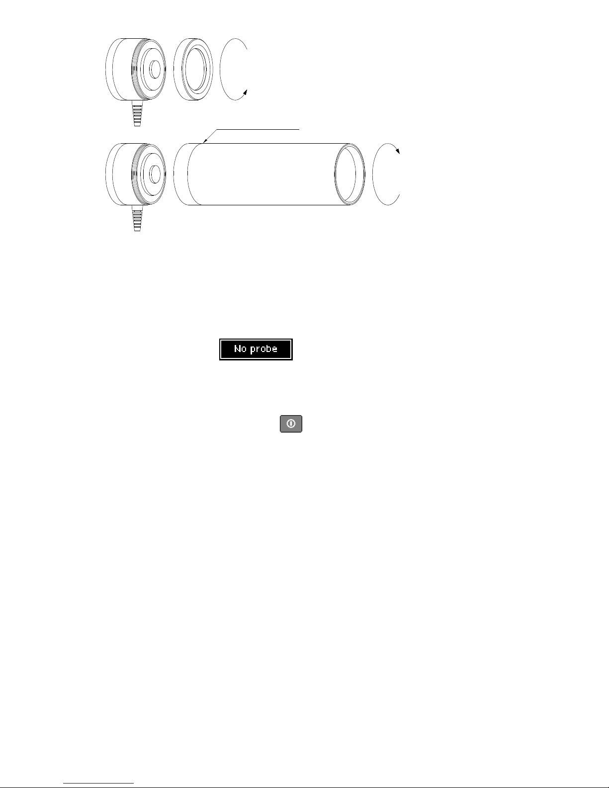
5.6. Working with luminance measure adapter
In order to connect luminance measure adapter, it's necessary to unscrew ring from measure probe receipt
field, and then screw on luminance adapter (Fig. 10).
Next, luminance measure mode should be turned on (look at: 5.1.2.4). It is necessary to pay special atten-
tion to proper select field aperture from the list. This has fundamental meaning when computing lumi-
nance signal measured through probe. Proper instrument results are only provided with SONOPAN lumi-
nance measure adapters, because they are structurally fitted to the computation algorithm.
When returning from luminance to illuminance mode, it’s necessary to screw on early unscrewed ring.
This warrants proper probe directional characteristic.
–
18 –
field aperture marker
Fig. 10. Connecting luminance measure adapter.
5.7. Working without measure probe
During initialization process control unit checks up the presence of measure probe. Instrument initialize
probe and reads its parameters: type, firmware version, number and values of measurement ranges, com-
patibility witch luminance mode. Then control unit checks up its authorization to work with the probe.
When measure probe is not present or the meter is not authorized to work with it, after closing data plate,
error message will appear: , and on status bar, meter will do not display measurement
range. Starting new measure is forbidden, but memory exploring and transmission memory content to PC
are still available. Measure probe unit must by connected only after turning instrument off.
5.8. Turning off the instrument
Instrument can be turned off only by key . During power off, meter stores in non volatile memory:
setup, computed integral and statistic values, comments and positions of menu pointers. This procedure is
omitted if meter will be turned off by battery extraction.
6. COMMUNICATION WITH PC
Connecting luxmeter L-100 to PC is realized through RS-232C connector (Fig. 2) and cable provided
together with the device.
6.1. Transmission protocol
Serial data transfer parameters:
• 1200÷9600bds,
• 8 data bits,
• 1 start bit,
• 1 stop bit,
• no parity bit.
Communication between PC and instrument is bidirectional, i.e. meter sends data and also can be con-
trolled by PC.
6.2. Automatic power on
If meter is connected to PC, first data request send from PC, automatically turns on the meter. It allows
full remote controlling the instrument. It is recommended to detach transmission cable, when meter is not
used with PC software. It will help to avoid uncontrolled instrument activations.

–
19 –
6.3. PC software
RF.exe MS Windows compatible software is supplied with the meter. After connecting meter to PC, it's
necessary to proper configure serial transmission port (setup number of serial port and baud rate, same as
set in the meter). Program permits remote control of the instrument and downloading measure memory
content. Downloaded measurements are stored on PC’s hard disk in human friendly text format, also ap-
probated by any spreadsheet application (separator character is tabulator).
7. POWER SUPPLY
Luxmeter L-100 is powered through single 9V battery. It is recommend to use alkaline batteries with big
capacity of the 6LR61 type or similar. They assure 20 hours of non-interrupted instrument work.
Battery container is located on back side of control unit.
7.1. Control of battery supply.
When instrument is operating, condition of battery is controlled. Battery gauge is located on status bar.
When battery is exhausted, icon will looks like: . Then battery must be replaced with new one. In other
case instrument will power off when voltage drops below critical level.
7.2. Automatic power off.
Luxmeter L-100 was provided with two automatic power off systems. First one, turns off the meter when
supply voltage is lower than critical. Second one, turns off the instrument after set idle time.
The idle time is counted from last key pressing or from finishing the measure.
8. RECOMMENDATIONS FOR INSTRUMENT USE
• It's forbidden to expose instrument on falls, shakes neither on any other factors that might produce
mechanical damages.
• The protection of measurement probe should be removed only for duration of the measurement, pro-
tecting the optical element against the smudge of dirt.
• In case when measurement range overload occurs on the highest measurement range, it's recom-
mended to remove probe from measure field or shield it from high radiation. Long exposition to high
radiation may damage measure probe .
• It's forbidden to connect or disconnect measure probe during instrument operation.
• In case when error message will appear: user may use key to save result to
device memory. Next, instrument should be turned off and on, to reinitialize measure probe.
• Optical element of measure probe can be cleaned with soft material damped with clean alcohol.
• Lens of luminance measure adapter can be cleaned from dust by small soft clean brush or stream of
compressed air. Product in spray that operate similar to compressed air use with caution. They must
be kept vertical during the cleaning process.
• User should hold the glass element of the luminance adapters in absolute cleanness from the side of
attached measuring probe, because the possible smudge of dirt has influence on measurement result.
Cleaning process is like in the case of the measuring probe cleaning.
• It's necessary to protect instrument from wet and aggressive chemical factors that can destroy instru-
ment elements.
• It's forbidden to connect to the instrument sockets different devices, for which they stayed predicted.
• Instrument should be kept and transported in factory container.
• In case of longer storage user should take the battery out from the device .

–
20 –
9. WARRANTY AND REPAIRS
Luxmeter L-100 is shipped with one year warranty from day of purchase. It does not require any special
maintenance treatments.
All repairs of the instrument are performed by the manufacturer
10. CE MARKING AND CONFORMANCE TO EU COUCIL DIRECTIVES
The product described in this instruction conforms to following EU Council Directives:
89/336/EEC Electromagnetic compatibility.
The conformance to above-mentioned
requirements is confirmed by CE mark.
This product cannot be thrown away with household waste. Deposit the product in
an authorized electrical and electronic waste collection area for recycling. Contact
local Municipal Bureau or nearest waste disposal company to get more detailed in-
formation.
Table of contents
Other SONOPAN Measuring Instrument manuals


Popular Measuring Instrument manuals by other brands

Alpen Optics
Alpen Optics CRESTONE XP 7x24 instruction manual

Windrock
Windrock Spotlight A3910 user manual

Hauber Elektronik
Hauber Elektronik HE250 Series manual

F&J
F&J DF-75L-Li Technical manual

Lincoln Electric
Lincoln Electric K283-1 Operator's manual

Spectrum Technologies
Spectrum Technologies Field Scout TDR 350 product manual


