SDI/ アナログマルチ入力アダプター BKM-61D
4
SDI/ アナログマルチ入力アダプター BKM-61D
SDI/ アナログマルチ入力アダプター BKM-61D は、ソニー
BVM-A シリーズカラービデオモニター用のビデオ信号入力
アダプターです。モニター背面の入力オプションスロットに
装着することで、モニターに 4:2:2コンポーネントデジタ
ル、コンポジットデジタル、アナログコンポジット、Y/C
の各信号を入力することができます。
機能
シリアルデジタル信号/アナログコンポジッ
ト信号用デコーダー
内蔵のデコーダーにより、525/625 コンポーネントデジタル
および NTSC / PAL コンポジットデジタル信号、NTSC
/ PAL / PAL-M / SECAM のアナログコンポジット信
号、Y/C 信号をデコードできます。
シリアルデジタル信号/アナログコンポジッ
ト信号用入出力端子
シリアルデジタル信号入力用端子を 2 つ、モニター出力端子
を 1 つ、アナログ入出力端子を 3 組装備しています。アナロ
グ入出力端子のうち上の 2 組を、Y/C セパレートの入出力
端子として使用することができます。
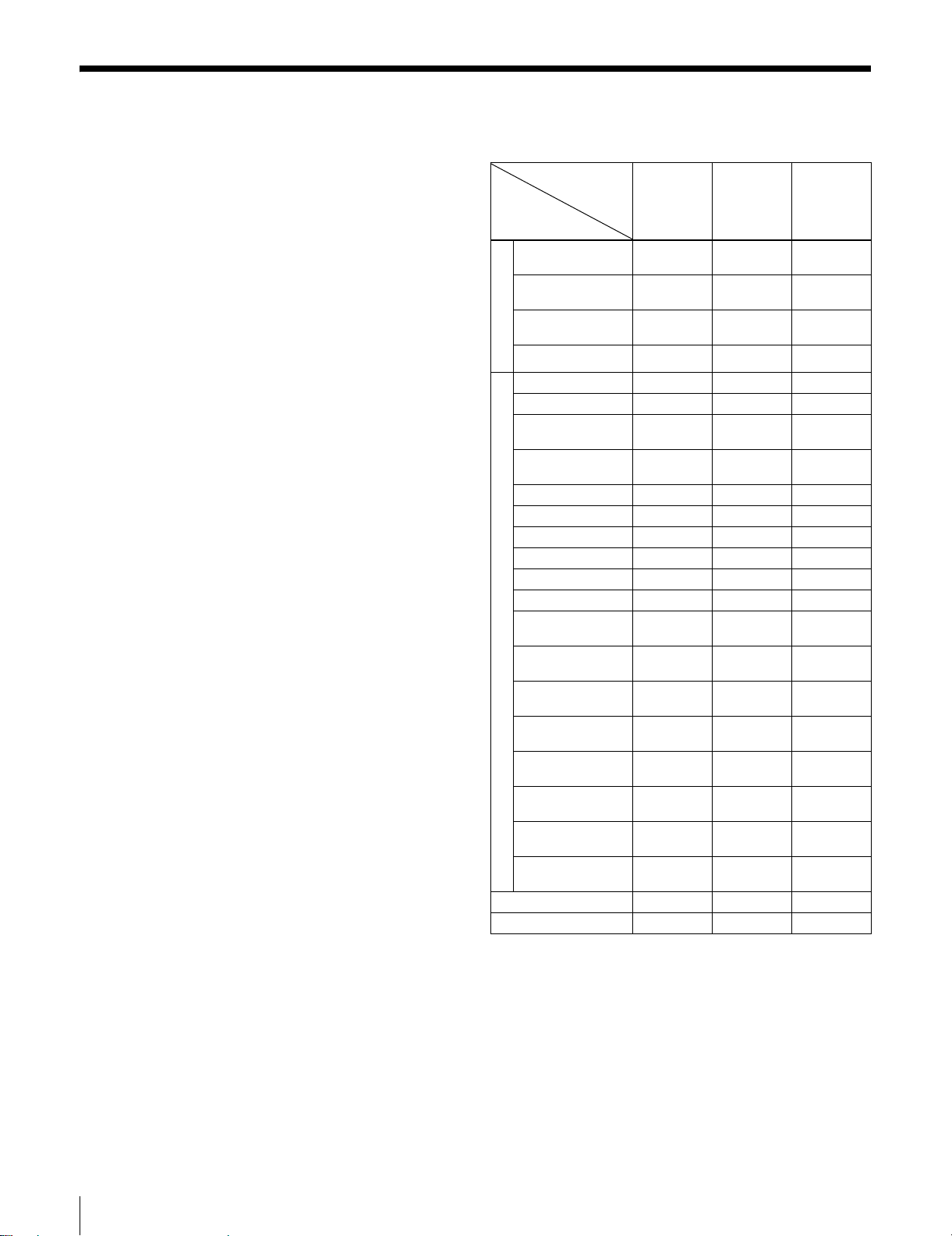
入出力端子の使いかた
入出力端子と入力可能な信号
入出力端子の構成と、入力可能な信号を下図に示します。
シリアルデジタル信号の入力
1、2端子に入力できます。このうち一方の入力信号を選
び、3端子からモニター出力させることができます。3端
子には、75Ω 終端器を取り付ける必要はありません。
ご注意
•MONITOROUT 出力は、INPUTCONFIGURATION メ
ニューで設定した入力番号のフォーマット (AUTO の場合
は、最後に受像していた信号のフォーマット ) 以外では正
しく出力されません。
•MONITOROUT 出力は、装着したビデオモニターの電源
が ON された状態で出力されます。スタンバイ状態では出
力されません。
•MONITOROUT 出力は、本線系出力としての規格を満足
していません。
◆ INPUTCONFIGURATIONメニューについて詳しくは、ご使用
のビデオモニターのオペレーションマニュアル「C入力チャン
ネルの設定−INPUTCONFIGURATIONメニュー」をご覧くだ
さい。
アナログコンポジット信号の入力
4、6、8端子に入力できます。それぞれ 5、7、9端子
からループスルー出力させることができます。ループスルー
出力させないときは、5、7、9端子に 75Ω 終端器を取
り付けてください。
Y/C 信号の入力
4端子に Y 信号、6端子に C 信号を入力できます。それぞれ
5、7端子からループスルー出力させることができます。
ループスルー出力させないときは、5、7端子に 75Ω終
端器を取り付けてください。
◆ BKM-61D をビデオモニターの入力オプションスロットに装着す
る方法については、「ビデオモニターへの装着」(11 ページ)を
ご覧ください。
各端子への入力信号の割り付け
入力アダプターを組み込んだ後、ビデオモニターの INPUT
CONFIGURATION メニューで、入力チャンネルの各種設定
を行ってください。設定を行わないと、装着した入力アダプ
ターが正しく動作しないことがあります。
◆ INPUTCONFIGURATIONメニューについて詳しくは、ご使用
のビデオモニターのオペレーションマニュアル「C入力チャン
ネルの設定−INPUTCONFIGURATIONメニュー」をご覧くだ
さい。
シリアルデジタル信号
シリアルデジタル信号
アナログコンポジット信号
アナログコンポジット信号
アナログコンポジット信号
Y
C