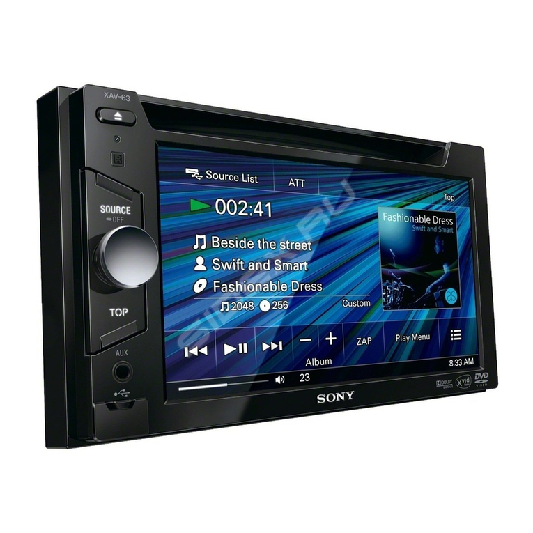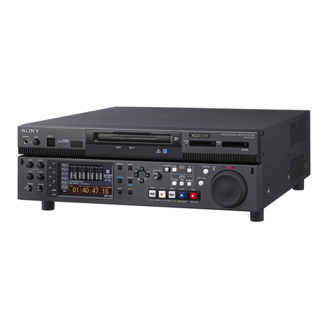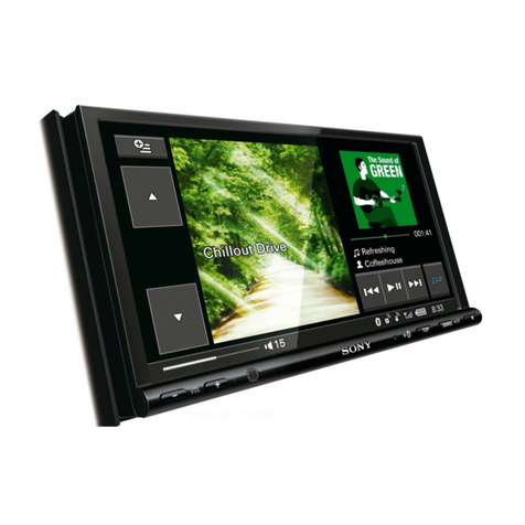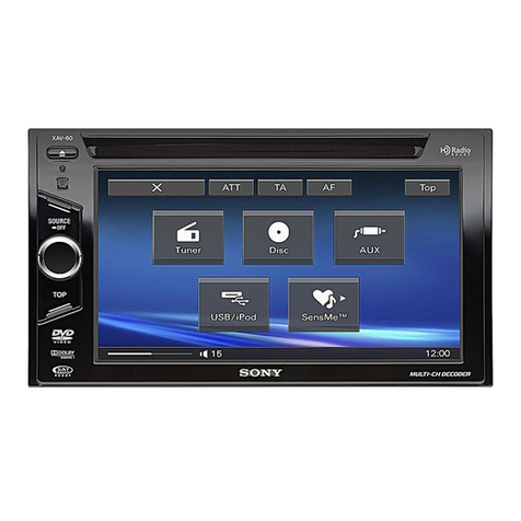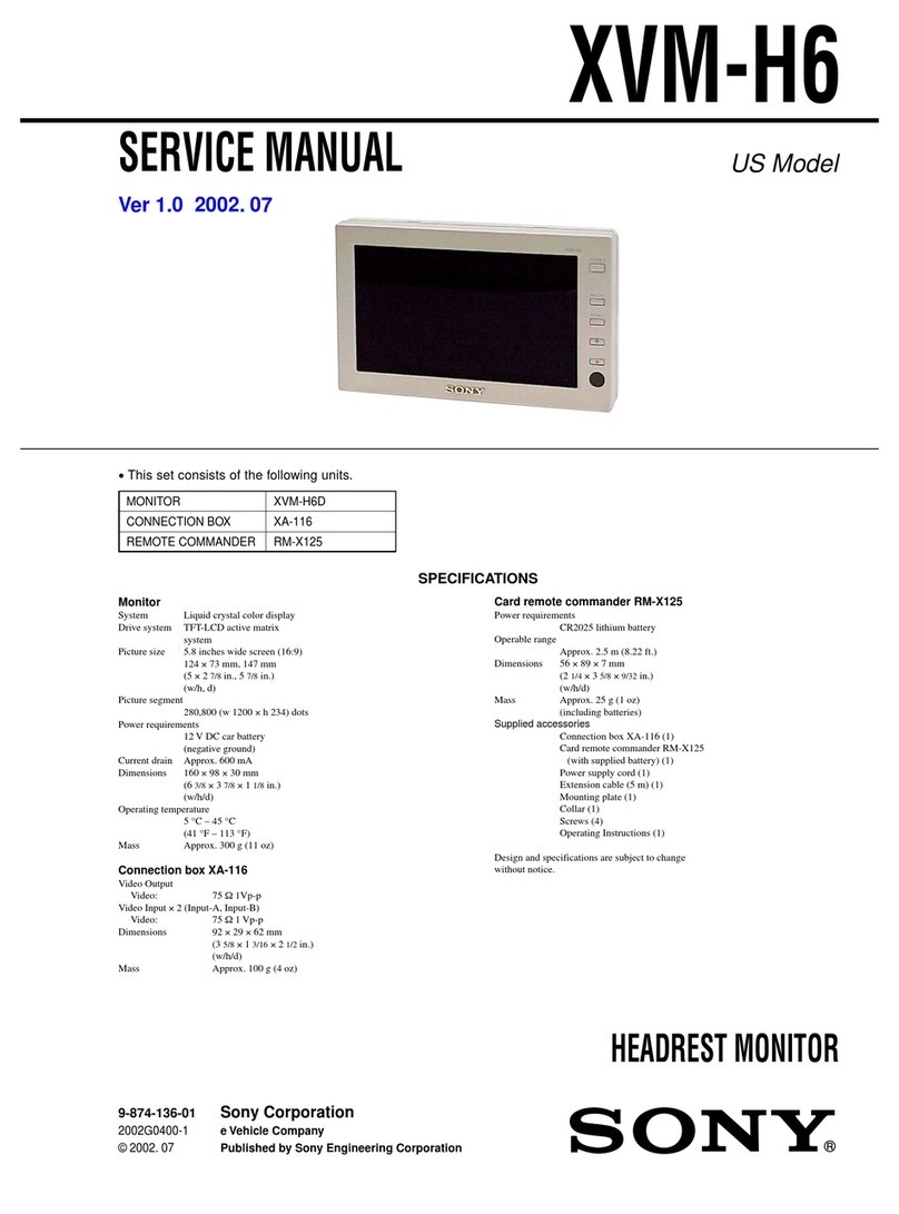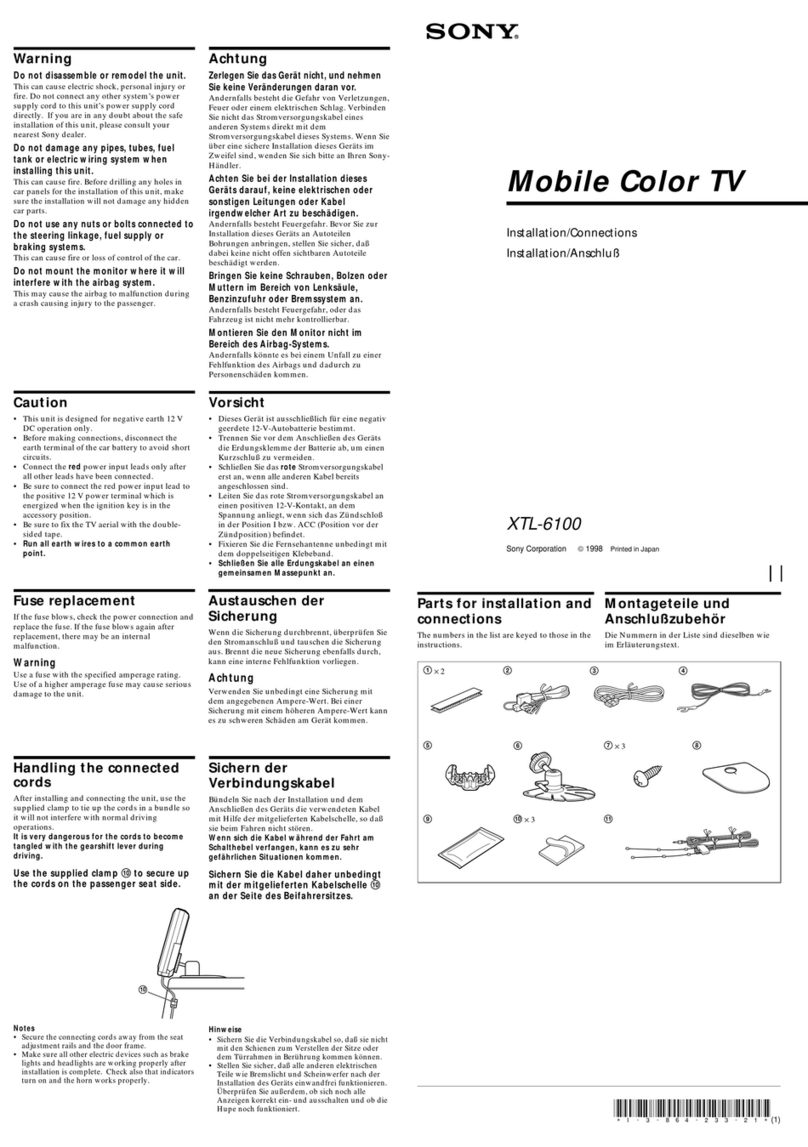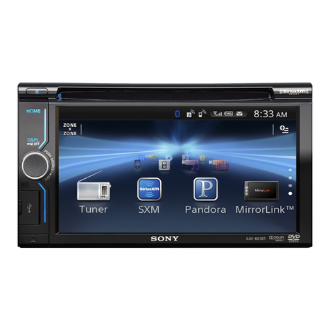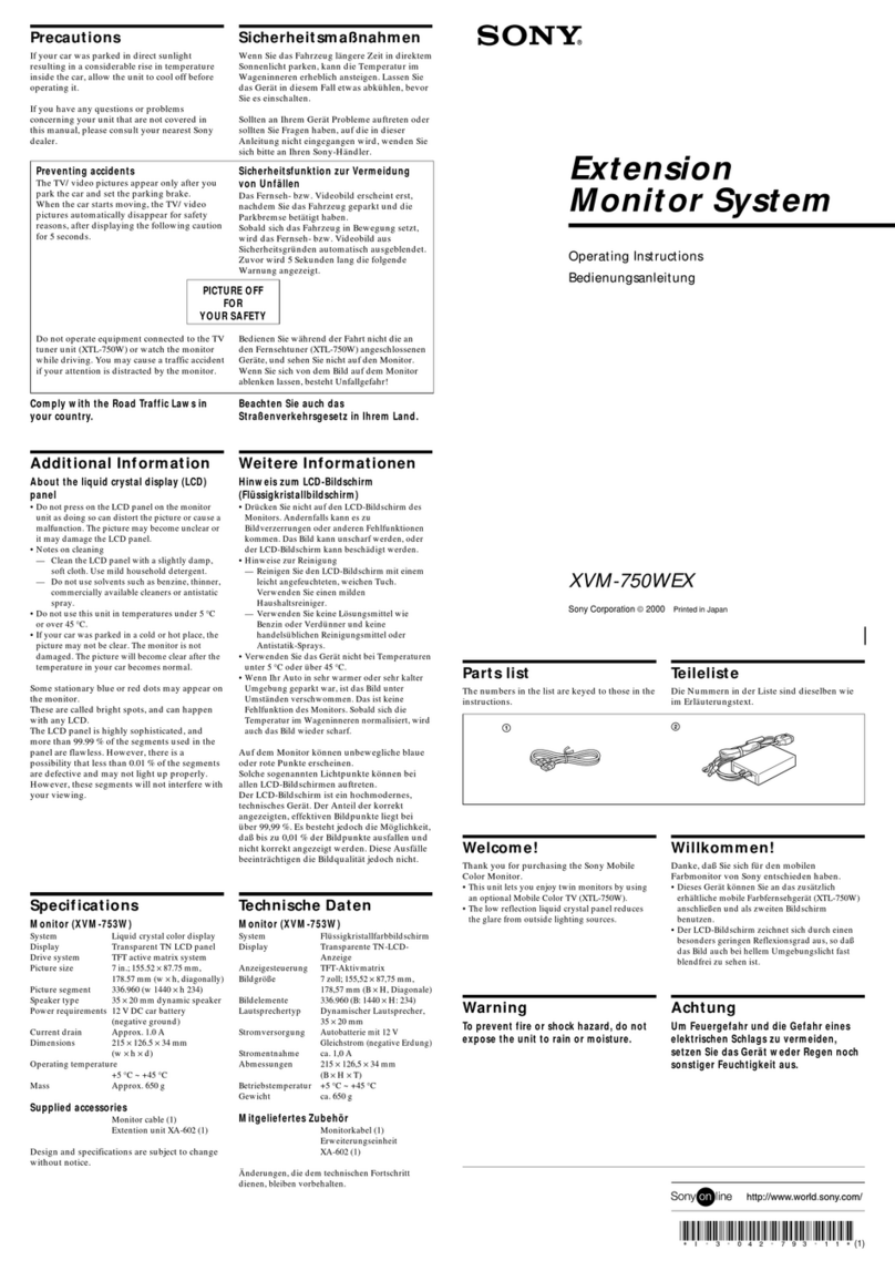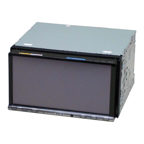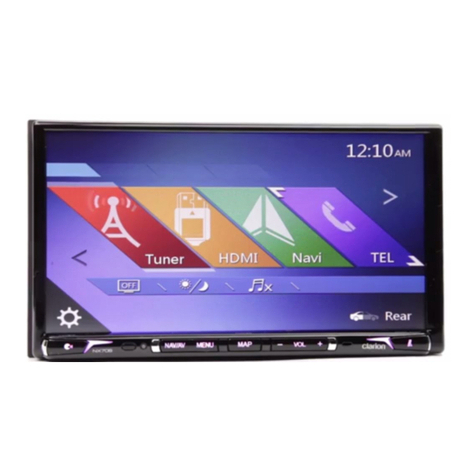
XAV-AX5600
3
Sony CONFIDENTIAL
For Authorized Servicer
1. SERVICING NOTES ................................................ 4
2. GENERAL ..................................................................... 19
3. DISASSEMBLY
3-1. Disassembly Flow.............................................................. 21
3-2. Mini Fuse (Blade Type), Cover ......................................... 22
3-3. Front Panel Block .............................................................. 23
3-4. Cable for Automobile (USB1),
Cable for Automobile (USB2) ........................................... 24
3-5. MAIN Board ...................................................................... 25
3-6. Flexible Flat Cable (60 Core), DISPLAY Board-1............ 26
3-7. DISPLAY Board-2 ............................................................. 27
3-8. BT Antenna ........................................................................ 28
3-9. Liquid Crystal Display, Panel Sub Assy ............................ 29
4. ELECTRICAL ADJUSTMENTS ........................... 30
5. DIAGRAMS
5-1. Block Diagram - AUDIO Section -.................................... 32
5-2. Block Diagram - VIDEO Section -.................................... 33
5-3. Block Diagram - POWER SUPPLY Section -................... 34
5-4. Printed Wiring Board
- MAIN Board (Component Side) -................................... 36
5-5. Printed Wiring Board
- MAIN Board (Conductor Side) -..................................... 37
5-6. Schematic Diagram - MAIN Board (1/4) -........................ 38
5-7. Schematic Diagram - MAIN Board (2/4) -........................ 39
5-8. Schematic Diagram - MAIN Board (3/4) -........................ 40
5-9. Schematic Diagram - MAIN Board (4/4) -........................ 41
5-10. Printed Wiring Board - DISPLAY Board (Side A) -.......... 42
5-11. Printed Wiring Board - DISPLAY Board (Side B) -.......... 43
5-12. Schematic Diagram - DISPLAY Board (1/5) - .................. 44
5-13. Schematic Diagram - DISPLAY Board (2/5) - .................. 45
5-14. Schematic Diagram - DISPLAY Board (3/5) - .................. 46
5-15. Schematic Diagram - DISPLAY Board (4/5) - .................. 47
5-16. Schematic Diagram - DISPLAY Board (5/5) - .................. 48
6. EXPLODED VIEWS
6-1. Overall Section .................................................................. 65
6-2. MAIN Board Section ......................................................... 66
6-3. Front Panel Section............................................................ 67
7. ELECTRICAL PARTS LIST ................................. 68
8. ACCESSORIES .......................................................... 81
TABLE OF CONTENTS
NOTES ON CHIP COMPONENT REPLACEMENT
• Never reuse a disconnected chip component.
• Notice that the minus side of a tantalum capacitor may be dam-
aged by heat.
FLEXIBLE CIRCUIT BOARD REPAIRING
• Keep the temperature of soldering iron around 270 °C during
repairing.
• Do not touch the soldering iron on the same conductor of the
circuit board (within 3 times).
• Be careful not to apply force on the conductor when soldering or
unsoldering.
iriusXM-Ready® allows you to Listen to ad-free
usic, plus all the sports, talk, comedy, news
overage, all in one place. (SiriusXM Connect Tuner
nd subscription required. Sold separately.) For
ore information, visit www.siriusxm.com.
irius, XM and all related marks and logos are
rademarks of Sirius XM Radio Inc. All rights
eserved.
he Bluetooth® word mark and logos are registered
rademarks owned by Bluetooth SIG, Inc. and any
se of such marks by Sony Corporation is under
icense. Other trademarks and trade names are
hose of their respective owners.
indows Media is either a registered trademark or
rademark of Microsoft Corporation in the United
tates and/or other countries.
his product is protected by certain intellectual
roperty rights of Microsoft Corporation. Use or
istribution of such technology outside of this
roduct is prohibited without a license from
icrosoft or an authorized Microsoft subsidiary.
pple and iPhone are trademarks of Apple Inc.,
egistered in the U.S. and other countries.
pple CarPlay is a trademark of Apple Inc.
ndroid Auto is a trademark of Google LLC.
ebLink is a registered trademark of Abalta
echnologies, Inc. in the U.S. and a trademark in the
ther countries.
he terms HDMI, HDMI High-Definition
ltimedia Interface, and the HDMI Logo
re trademarks or registered trademarks of
DMI Licensing Administrator, Inc.
ll other trademarks are trademarks of their
Copyrights
SYSSET
2021/04/2822:33:39(GMT+09:00)

