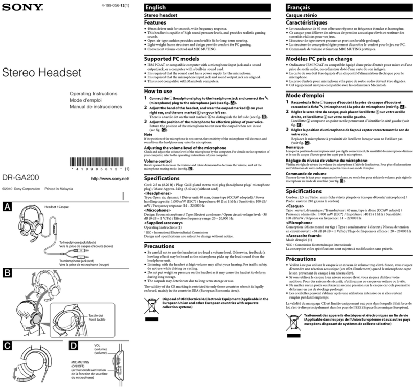
Sony WH-1000XM2 User manual

SERVICE MANUAL
Sony Video & Sound Products Inc.
9-896-427-01
2017H33-1
© 2017.08
WH-1000XM2
SPECIFICATIONS
WIRELESS NOISE CANCELING STEREO HEADSET
US Model
Canadian Model
AEP Model
UK Model
E Model
Australian Model
Chinese Model
Tourist Model
Ver. 1.0 2017.08
General
Communication system: BLUETOOTH Specication version 4.1
Output: BLUETOOTH Specication Power Class 2
Maximum communication range: Line of sight approx. 10 m
1)
Frequency band:
(AEP, UK)
Operating frequency:
BLUETOOTH 2,400 MHz - 2,483.5 MHz
NFC 13.56 MHz
Maximum output power:
BLUETOOTH < 20.0 dBm
NFC < 60 dBμA/m at 10 m
2.4 GHz band (2.4000 GHz - 2.4835 GHz)
Compatible BLUETOOTH proles2):
A2DP (Advanced Audio Distribution Prole)
AVRCP (Audio Video Remote Control Prole)
HFP (Hands-free Prole)
HSP (Headset Prole)
(30 ft)
Supported Codec3):SBC 4) , AAC 5) , LDAC, aptX, aptX HD
Supported content protection method: SCMS-T
Transmission range (A2DP):
Included items:
Wireless noise canceling stereo headset (1)
20 Hz - 20,000 Hz (Sampling frequency 44.1 kHz)
20 Hz - 40,000 Hz (Sampling frequency LDAC 96 kHz,
990 kbps)
Micro-USB cable (approx.50 cm (19 3/4 in.)) (1)
Headphone cable (approx.1.5 m (59 1/8 in.)) (1)
Carrying case (1)
Plug adaptor for airplane 6) (1)
Reference Guide (1)
Operating Instructions (1)
Other documents (1 set) (US, CND, AEP, UK, LA)
1) The actual range will vary depending on factors such as
obstacles between devices, magnetic elds around a microwave
oven, static electricity, reception sensitivity, antenna’s
performance, operating system, software application, etc.
2) BLUETOOTH standard proles indicate the purpose of
BLUETOOTH communications between devices.
3) Codec: Audio signal compression and conversion format
4) Subband Codec
5) Advanced Audio Coding
6) Depending on the in-ight entertainment services, it may not be
supported.
Wireless noise canceling stereo
headset
Power source:
DC 3.7 V:Built-in lithium-ion rechargeable battery
DC 5 V: When charged using USB
Mass: Approx.275 g (9.70 oz)
Operating temperature: 0 °C to 40 °C (32 °F to 104 °F)
Usage hours:
When connecting via the BLUETOOTH device
Music playback time:
Max. 30 hours (NC ON), Max.38 hours (NC OFF)
Communication time:
Max. 30 hours (NC ON), Max.38 hours (NC OFF)
Standby time:
Max. 40 hours (NC ON), Max.200 hours (NC OFF)
When connecting via the headphone cable with NC ON:
Max. 40 hours
Note: Usage hours may be shorter depending on the Codec
and the conditions of use.
Charging time:
Approx. 4 hours
(About 70 minutes of music playback is possible after
10 minutes charging.)
Note: Charging and usage hours may be dierent depending
on the conditions of use.
Charging temperature: 5 °C to 35 °C (41 °F to 95 °F)
Receiver
Type: Closed, Dynamic
Driver unit: 40 mm
Frequency response:
4 Hz - 40,000 Hz (JEITA) (when connecting via the headphone
cable with the unit turned on)
Impedance:
46 Ω (1 kHz) (when connecting via the headphone cable with
the unit turned on)
14 Ω (1 kHz) (when connecting via the headphone cable with
the unit turned o)
Sensitivity:
103 dB/mW (when connecting via the headphone cable with
the unit turned on)
98 dB/mW (when connecting via the headphone cable with
the unit turned o)
Microphone
Type: Electret condenser
Directivity: Omni directional
50 Hz - 8,000 HzEective frequency range:
System requirements for battery
charge using USB
USB AC adaptor (US, CND, AEP, UK, LA)
Using a commercially-available USB AC adaptor capable of feeding
in 1.5 A or 0.5 A
(the charging time will be shorter with a USB AC adaptor capable of
feeding in 1.5 A)
Personal Computer
(As of August 2017)
Personal Computer with pre-installed with any of the following
operating systems and USB port:
Operating Systems
(when using Windows)
Windows®®
10 Pro
Windows®®
8.1 Pro
Windows®®
8 Pro
10 Home / Windows
8.1 / Windows
8 / Windows
Windows®7
Home Basic / Home Premium / Professional / Ultimate
(when using Mac)
Mac OS X (version 10.9 or later)
Design and specications are subject to change without notice.
The LDAC™ name and logo is a trademark of Sony Corporation.
The Bluetooth® word mark and logos are registered trademarks
owned by the Bluetooth SIG, Inc. and any use of such marks by
Sony Corporation is under license.
The N-Mark is a trademark or registered trademark of NFC Forum,
Inc. in the United States and in other countries.
Windows is a registered trademark or trademark of Microsoft
Corporation in the United States and/or other countries.
Mac, OS X,iPhone and iPod touch are trademarks of Apple Inc.,
registered in the U.S. and other countries.
“Made for iPod” and “Made for iPhone” mean that an electronic
accessory has been designed to connect specically to iPod or
iPhone, respectively, and has been certied by the developer to
meet Apple performance standards.Apple is not responsible for
the operation of this device or its compliance with safety and
regulatory standards. Please note that the use of this accessory
with iPod or iPhone may aect wireless performance.
Qualcomm® is a trademark of Qualcomm Incorporated,registered
in the United States and other countries,used with permission.
Qualcomm aptX™ audio is a trademark of Qualcomm Technologies
International, Ltd., registered in the United States and other
countries, used with permission.
Android is a trademark of Google Inc.
Other trademarks and trade names are those of their respective
owners.
Except Chinese model Chinese model
ᵤ冐
彾嬓䱟乃濕CMVFUPPUI夨㞠5/2䆬
廷⅞濕CMVFUPPUI夨㞠∃䋫䪭下3
㙤⢋彾嬓剧♘濕䙘太嵁䤟上21!n2*
柵䋫㱆㬙濕3/5!HI{㱆㬙濃3/5111!HI{!.!
3/5946!HI{濄
柵䋫剧♘濕3511!NI{!.!3594/6!NI{
⌵⭨∃䋫濕Ŭ!31!eCn濃FJSQ濄
⬝䗨CMVFUPPUI悱仒⊳嬒3*濕!
B3EQ濃Bewbodfe!Bvejp!Ejtusjcvujpo!
Qspgjmf濄
BWSDQ濃Bvejp!Wjefp!Sfnpuf!Dpouspm!
Qspgjmf濄
IGQ濃Iboet.gsff!Qspgjmf濄
ITQ濃Ifbetfu!Qspgjmf濄
㒓㉥䗨乺奇䝥◌4*濕TCD5*ɀBBD6*ɀMEBDɀ!
bquY™ɀbquY!IE
㒓㉥䗨⬝ὁ㈈㔝㰹濕TDNT.U
Ẅ廷剧♘濃B3EQ濄濕!
31!I{!.!31111!I{濃愫㞛柵䋫55/2!lI{濄
31!I{!.!51111!I{濃愫㞛柵䋫MEBD!:7!lI{濇!
::1!lcqt濄
≩堩䇍␥濕!
㕄丣斱◎䨯ặ⡔侗㚞濃2濄
Njdsp.VTC彂㌉丣濃上61!dn濄濃2濄
侗㚞彂㌉丣濃上2/6!n濄濃2濄
ἣ㎞䘶濃2濄
桂㚞ᵷ䒌廐㌉㌶⢘7*濃2濄
⌦佧㉫⊻濃㚐柙濄濃2濄
ợ䒌存㕲濃2濄
Ḻ㓫Ṛ濃2⢻濄
2*!⬂斩剧♘⭪太嬢⡫ᶯ敘䗨昀䟱䇍ɀ⼒㱆㿭⏌
♘䗨䠥⚞ɀ暽䒙ɀ㌉㒚㿙㒳⸊ɀ⢍丣⾋偡ɀ
㐱Ề䱟乃ɀ廓Ṛⷸ䒌䥯ⷳ䪭♄䲄佰⌼≺Ɂ
濃2濄
3*!CMVFUPPUI㝫K悱仒⊳嬒㖓㉫嬢⡫ᶯ敘
CMVFUPPUI彾嬓䗨䙒䗨Ɂ
4*!乺奇䝥◌濕杗柵ὅ⍛⋯亍⏰廐㋆㞠
5*!⪴柵ⶊ乺奇䝥◌
6*!樼下杗柵乺䝥
7*!太桂垰ᶑ䗨⦕ᶴ㙱∅佰⫾濇⍓偡ᵱ㒓㉥Ɂ
! 䣥㫆㌶
!
! 弽㖓䒌桂㚞ᵮ䗨㌶⢘廐㌉◌Ɂ孛ᵱ壥㌶
䒙㷴㌶⸋Ɂ
㕄丣斱◎䨯ặ⡔侗㚞
䒙㷴濕!
ED!4/8!W濕仒摦䤟⪴₩䒙䒙㯄
ED!6!W濕ợ䒌VTC₩䒙㕚
岌愳濕上386!h
ⵉỀ㶍⸊濕1!Į兗51!Į
栁⫾∃佻濕4!X
ợ䒌㕚敘濕!
彾弫CMVFUPPUI嬢⡫彂㌉㕚
! 杗ᶴ㐑㒢㕚敘濕!
!!㙤⡾41⭳㕚濃斱◎濄濇!
㙤⡾49⭳㕚濃斱◎濄
! 彾嬓㕚敘濕!
!!㙤⡾41⭳㕚濃斱◎濄濇!
㙤⡾49⭳㕚濃斱◎濄
! ⻩㚞㕚敘濕!
!!㙤⡾51⭳㕚濃斱◎濄濇!
㙤⡾311⭳㕚濃斱◎濄
⚌斱◎䗨〩ℙᵯ彾弫侗㚞彂㌉丣彂㌉㕚濕!
!!㙤⡾51⭳㕚
㱌び柝濕ợ䒌㕚敘⍓偡Ṿ廧䝑濇太乺奇䝥
◌⏰ợ䒌䈚ℙ佰⫾Ɂ
₩䒙㕚敘濕!
上5⭳㕚
濃₩䒙21Ⅺ搃⍲⍓㐑㒢杗ᶴ上81Ⅺ搃Ɂ濄
㱌び柝濕₩䒙㕚敘⏰ợ䒌㕚敘⍓偡Ṿ♄ợ
䒌䈚ℙ佰Ɂ
₩䒙㶍⸊濕6!Į兗46!Į
㌉㒚◌
䯟⛯濕⭥救濇∌⽥
槕∌⊹₧濕51!nn
柵䋫ⷸ濕!
5!I{!.!51111!I{濃KFJUB濄濃⚌㚐㚞⎓䗨
〩ℙᵯ彾弫侗㚞彂㌉丣彂㌉㕚濄
斟ㇻ濕!
57!Ã濃2!lI{濄濃⚌㚐㚞⎓䗨〩ℙᵯ彾弫
侗㚞彂㌉丣彂㌉㕚濄
25!Ã濃2!lI{濄濃⚌㚐㚞救䗨〩ℙᵯ彾弫
侗㚞彂㌉丣彂㌉㕚濄
㿙㒳⸊濕!
214!eC0nX濃⚌㚐㚞⎓䗨〩ℙᵯ彾弫侗㚞
彂㌉丣彂㌉㕚濄
:9!eC0nX濃⚌㚐㚞救䗨〩ℙᵯ彾弫侗㚞彂
㌉丣彂㌉㕚濄
渊₯栲
䯟⛯濕槟㛥ặ䒙⬝◌
㉫⍵⾋濕㉫⍵
㙭㒬柵䋫剧♘濕61!I{!.!9111!I{
ợ䒌VTC⭝䒙㯄₩䒙䗨䱟乃壥㮦
VTCḈ㲥䒙㷴彦悱◌
孛ợ䒌ỿ䒙愳ᶞ2/6!Bㅺ1/6!B䗨ⵦ⒒VTCḈ㲥䒙
㷴彦悱◌
濃ợ䒌ỿ䒙愳ᶞ2/6!B䗨VTCḈ㲥䒙㷴彦悱◌⍓
亍䝑₩䒙㕚敘濄
ᶎḞ䒙偵
濃ㆎ㫆兗3128ⷘ9㙬濄
柨堩ṉᵯṟびᵤ䤱㐱Ề䱟乃⏰VTC䩓⍇䗨ᶎḞ䒙
偵濕!
㐱Ề䱟乃
濃⺷ợ䒌Xjoepxt㕚濄
Xjoepxtŧ21!Ipnf!0!Xjoepxt®!21!Qsp
Xjoepxt®!9/2!0!Xjoepxt®!9/2!Qsp
Xjoepxt®!9!0!Xjoepxt®!9!Qsp
Xjoepxt®!8!
Ipnf!Cbtjd!0!Ipnf!Qsfnjvn!0!
Qspgfttjpobm!0!Vmujnbuf
濃⺷ợ䒌Nbd㕚濄
Nbd!PT!Y濃21/:ㅺ㙘樼䆬㚐濄
嬢嬅⏰夨㞠⣦㙭⌼㙘濇⾹ᵱ⍊垰彾䝉Ɂ
CAUTION
Danger of explosion if battery is incorrectly replaced.
Replace only with the same or equivalent type.
注意
如果电池更换不当会有爆炸危险
只能用同样类型或等效类型的电池来更换
WH-1000XM2
2
SECTION 1
SERVICING NOTES
DESTINATION ABBREVIATIONS
The following abbreviations for model destinations are used in this
service manual.
• Abbreviations
AUS : Australian and New Zealand models
CH : Chinese model
CND : Canadian model
JE : Tourist model
LA : Latin American model
RU : Russian (CIS area: Except for Moldova) model
MODEL IDENTIFICATION
By the print contents on the slider lower (L) of L-ch, it can distin-
guish the destination of this unit.
slider lower (L)
US, CND, LA
E, AUS, JE, RU CH
AEP, UK
COLOR VARIATIONS
(B) Black
(N) Champagne Gold
CHECKING THE SERIAL NUMBER
The serial number can be checked with the label that is pasted in-
side of left hanger.
Refer to the following figure.
Serial number
label
NOTES FOR REPAIR OF BOARDS
When boards installed in this unit are defective, it is replaced by
the board.
Replace the complete mounted board or the whole parts including
the applicable board.
HANDLING OF SLIDER UPPER ASSY AND SLIDER
LOWER ASSY BY LUBRICANT APPLICATION
Lubricant (SANKOL) is applied to the slider upper assy and slider
lower assy. Be careful when handling so that you do not touch the
portion applied with the lubricant (SANKOL).
Lubricant (SANKOL) application position:
– Top view –
Lubricant
(SANKOL)
Lubricant
(SANKOL)
– Inside view –
Slider upper assy
– Inside view –
Slider lower assy
Lubricant
(SANKOL)
RESET METHOD
When resetting this unit, operate by following procedure.
Note: Even if this work is performed, device pairing information is not
deleted.
Procedure:
1. Connect this unit to a booted PC or optional USB AC adaptor
using the supplied micro-USB cable, set the charge status.
2. Press the [1] and [NC/AMBIENT] buttons simultaneously.
3. This unit be reset.
Connection:
or
1
NC/AMBIENT
micro-USB cable
The SERVICING NOTES contains important information for servicing. Be sure to read this section before repairing the unit.

WH-1000XM2
3
INITIALIZING METHOD
After completion of repairs, be sure to perform the following pro-
cedure to initialize this unit.
Note 1: When this work is performed, all device pairing information is
deleted and settings return to factory defaults.
Procedure:
1. Check that the micro-USB cable is not connected to this unit,
and turn off the power.
Note 2: If already power is turned off, check the micro-USB cable is not
connected, proceed to step 2.
Disconnect the
micro-USB cable.
Press the [1] button to turn the power off.
(Check that indicator is lighted off)
2. Press the [1] and the [NC/AMBIENT] buttons on the left chan-
nel side simultaneously for 7 seconds or longer.
1
NC/AMBIENT
3. The left channel side indicator (blue) flashes 4 times and the
settings return to factory defaults.
(Blue)
Note 3: When this unit is initialized, it might not be able to connect to
iPhone or PC.
In that case, delete the registration of this unit on iPhone or PC,
register the device again.
NOTES ON DISASSEMBLY
The precise noise canceling function of this unit is adjusted in the
production process.
Therefore, it is not possible to disassemble the portion affecting
the adjustment of the noise canceling function or to replace the
parts affecting it.
(It is not possible to adjust the noise canceling function)
Refer to the following for repairing and replacing the main parts.
• Disassembly Prohibited Portion
Left and right housing interior, do not disassemble of the latter
than the status of following figure.
If disassembling this unit to the latter than the status shown in the
figure below, malfunction will occur in adjustment of the noise
canceling function.
– Right housing interior – – Left housing interior –
Disassembly of parts other
than ornament and lithium
ion battery are prohibited.
Disassembly of parts other than
ornament, lower cover (L),
button, jack and L KEY board
are prohibited.
• Repairing and Replacing of Disassembly Prohibited
Portion
When parts of disassembly prohibited portion are defective, re-
placing by the SVX headphone assy (EXPLODED VIEWS: Ref.
No. HPN1).
Note 1: When the Ref. No. HPN1 is replaced, the serial number changes.
SVX headphone assy
(EXPLODED VIEWS: Ref. No. HPN1)
• Repairing and Replacing of Headband Block
Only the headband block cannot be repaired and replaced.
If it need to replace the headband block, replacing by the SVX
headphone assy (EXPLODED VIEWS: Ref. No. HPN1).
Note 2: When the Ref. No. HPN1 is replaced, the serial number changes.
Note 3: A portion of the slider parts can be replace with single part. Refer
to the exploded views for details.
SVX headphone assy
(EXPLODED VIEWS: Ref. No. HPN1)

WH-1000XM2
4
SECTION 2
DISASSEMBLY
• This set can be disassembled in the order shown below.
2-1. DISASSEMBLY FLOW
Note: Follow the disassembly procedure in the numerical order given.
2-2. EARPAD
Note 1: The left and right earpads can be removed using the same procedure.
This explanation uses illustrations from the left side.
SET
2-6. JACK
(Page 7)
2-4. LOWER COVER (L)
(Page 5)
2-5. BUTTON ASSY, L KEY ASSY
(Page 6)
L-ch R-ch
2-3. ORNAMENT (L) ASSY
(Page 5)
2-2. EARPAD
(Page 4)
2-7. ORNAMENT (R) ASSY
(Page 8)
2-8. LITHIUM ION BATTERY
(Page 9)
SLIDER BLOCK
2-9. SLIDER UPPER ASSY
(Page 10)
2-10. SLIDER LOWER ASSY
(Page 11)
2-11. SHAFT COVER
(Page 12)
2-12. CONFIRMING OPERATION OF
THE SLIDER BLOCK
(Page 12)
2earpad
–L-ch –
front plate (L)
earpad
Note 2: Confirm the positions of the hole
before installing the earpad.
top side
lower side
lower side
hole
1six claws
Installation direction for the earpad
– Inner view –

WH-1000XM2
5
2-3. ORNAMENT (L) ASSY (L-CH)
2-4. LOWER COVER (L) (L-CH)
4four screws
(P2.0 u8.0)
2cover stopper adhesive
3screen
1)&ZLUHVHWWLQJ
q; ornament
(L) assy
6Draw the NFC wire
out of the groove.
lower side
housing block (L-ch)
groove
NFC wire L NFC board
L NFC board
8NFC
adhesive
9ornament
adhesive
5Peel the MIC B sheet off of
the housing block (L-ch).
ornament adhesive
housing block
(L-ch)
MIC B sheet
ornament (L) block
ornament
adhesive
groove
1Peel the cover stopper adhesive
off of the housing block (L-ch).
1Peel the cover stopper adhesive
off of the housing block (L-ch).
7Peel the NFC adhesive
off of the ornament (L)
assy.
,QVWDOODWLRQSRVLWLRQRIWKHRUQDPHQWDGKHVLYH
–/FK–
guide line
guide line
electret cap
microphone
MIC FF holder
housing block
(L-ch)
lower side
1three tapping screws
(P2) (L = 5.0 mm)
2lower cover (L)
–L-ch –
lower side
Note: For the lower cover (L), lubricant (SANKOL) is applied to the areas
indicated in the figure below. If the lower cover (L) is removed,
be careful so that you do not touch the indicated areas.
Also, lubricant (SANKOL) is not applied to the repair parts for the
lower cover (L). Apply lubricant as necessary before installing them.
lower side
lower
cover (L)
– Inner view –

WH-1000XM2
6
2-5. BUTTON ASSY, L KEY ASSY (L-CH)
1NC ambient
button assy
2power
button
assy
4L KEY assy
Note: When installing the L KEY
assy, align the three bosses
and three holes.
terminal side
hole
hole
3L KEY FPC connector
(CN602)
boss
two bosses
–L-ch –
lower side
colored line
Insert straight into the interior.
flexible flat
cable
connector
OK
colored line
Insert at a slant.
flexible flat
cable
connector
NG
How to install the flexible flat cable
When installing the flexible flat cable,
ensure that the colored line is parallel
to the connector after insertion.
hole
OK NG
OK NG NG
NC ambient
button assy
power button
assy
NC ambient
button assy
power button
assy
jack wire
Push.
jack wire jack wire
L KEY FPC L KEY FPC L KEY FPC
/.(<)3&VHWWLQJ
,QVWDOODWLRQSRVLWLRQRIWKHEXWWRQDVV\
lower
side
lower
side

WH-1000XM2
7
2-6. JACK (L-CH)
How to install the jack
– Jack rear view –
There is no gap between
L JACK board and jack.
There is gap between
L JACK board and jack.
1screw
(2.0 u4.0)
4jack
–L-ch –
hole
3Remove the four solders.
lower side
jack
L JACK board L JACK board
OK NG
2Lift up the L JACK board block
in the direction of the arrow.
L JACK
board
jack

WH-1000XM2
8
2-7. ORNAMENT (R) ASSY (R-CH)
4four screws
(P2.0 u8.0)
lower
side
6Unlock the
connector.
(CN851)
R SUB
board
R TPAD
board
qs ornament
(R) assy
qa flexible flat cable
(12 core)
terminal side
7Draw the flexible flat cable
out of the connector.
terminal side
0Unlock the
connector.
(CN901)
2cover stopper adhesive
2cover stopper
adhesive
3screen
housing block (R-ch)
colored line
Insert straight into the interior.
flexible flat
cable
connector
OK
colored line
Insert at a slant.
flexible flat
cable
connector
NG
OK NG
How to install the flexible flat cable
When installing the flexible flat cable, ensure that the colored line
is parallel to the connector after insertion.
9ornament (R) block
8ornament
adhesive
guide line
guide line
ornament
adhesive
1Peel the cover
stopper adhesive
off of the housing
block (R-ch).
1Peel the cover
stopper adhesive
off of the housing
block (R-ch).
housing
block
(R-ch)
lower side
–R-ch –
Folding the flexible flat cable (12 core)
Installation direction for
the flexible flat cable (12 core)
Installation Sosition of the ornaPent adhesiYe
5Peel the MIC B sheet off of
the housing block (R-ch).
ornament adhesive
housing block
(R-ch)
MIC B sheet
ornament (R) block
electret cap
microphone
MIC FF holder
black line
black line
Turn
over. to R TOUCH board
to R SUB board to R SUB board
to R TOUCH board
black
line black
line
black
line
black line
Turn
over.
Before installing the flexible flat cable (12 core) to the board,
fold it with the following procedure.

WH-1000XM2
9
2-8. LITHIUM ION BATTERY (R-CH)
1Lift up the lithium ion battery block
in the direction of the arrow.
–R-ch –
2Peel the lithium ion battery block
off of the battery adhesive.
Note: When removing the lithium ion battery
from the battery adhesive, the lithium
ion battery cannot be reused.
Be sure to replace them with new parts.
lower side
5lithium ion battery
Note: When removing the lithium ion battery
from the battery adhesive, the lithium
ion battery cannot be reused.
Be sure to replace them with new parts.
battery
adhesive
3Remove the lithium ion battery block
in the direction of the arrow.
4cushion (BATT)
3DVWLQJ SRVLWLRQ RI WhHcXVhLRQ %$77
cushion (BATT)
lithium ion battery
guide line
guide line

WH-1000XM2
10
2-9. SLIDER UPPER ASSY
Note 1: The left and right slider upper assys can be removed using the same procedure.
This explanation uses illustrations from the right side.
slider block
housing block
JIG
When disassembling the unit, use the following jig.
Part No. Description
9-913-402-33 TOOL FOR DISASSEMBLING
housing block
3Extend the slider
block in the direction
of the arrow.
8slider upper assy
7Slide the slider
upper assy in
the direction
of the arrow.
slider
adhesive
slider
adhesive
slider upper assy
slider upper assy
– Inner view –
5Insert the jig into both sides and move it in the direction
of the arrows to peel off the slider adhesive.
Note 3: When using the jig, be careful so that the slider upper
assy and slider lower assy are not damaged.
Note 4: Before installing
the slider upper
assy, peel off the
release paper of
the slider adhesive.
2two tapping
screws (P2)
(L = 5.0 mm)
–R-ch –
claw
claw
slider lower assy
slider upper assy
4Insert the jig from the screwed side and
remove the two claws.
Note 3: When using the jig, be careful so that
the slider upper assy and slider lower
assy are not damaged.
1Fold the
housing block
in the direction
of the arrow.
slider
lower
assy
6Remove the entire housing block
by removing the slider lower assy
in the direction of the arrow.
Note 2: Lubricant (SANKOL) is applied to the slider upper assy and slider lower assy.
Be careful when handling so that you do not touch the portion applied with the
lubricant (SANKOL). For the application location of the lubricant (SANKOL),
refer to “HANDLING OF SLIDER UPPER ASSY AND SLIDER LOWER
ASSY BY LUBRICANT APPLICATION” on page 2.

WH-1000XM2
11
2-10. SLIDER LOWER ASSY
Note 1: The left and right slider lower assys can be removed using the same procedure.
This explanation uses illustrations from the right side.
3
2
1
2
1
hole
hole
boss
boss
guide line
housing block
slider lower assy
housing
block
groove
hinge assy
5HOD\FDEOHVHWWLQJ
OK
NG
NG
6slider lower assy
Note 3: When installing the slider lower assy,
align the two bosses and two holes.
5Remove the slider lower assy
in the direction of the arrow.
Twist the relay cable
three times.
Move the relay cable
to the right side.
The relay cable
is in the center.
4two screws
(1.7 u4.5)
–5FK–
Note 4: The slider lower assy and hinge assy are
attached tightly. When detaching the slider
lower assy, pull out in the direction of the
arrows along the guide line as shown in the
figure below.
white point
Push the white point of the
relay cable into the groove.
Draw out the relay
cable in the direction
of the arrow.
The relay cable is
not in the groove.
The relay cable
is not twisted
three times.
1Extend the housing block
in the direction of the arrow.
2Rotate the
housing block
in the direction
of the arrow.
3Draw the relay cable
out of the groove in
slider lower assy.
groove
Note 2: Lubricant (SANKOL) is applied to the slider lower assy. Be careful when
handling so that you do not touch the portion applied with the lubricant
(SANKOL). For the application location of the lubricant (SANKOL), refer
to “HANDLING OF SLIDER UPPER ASSY AND SLIDER LOWER ASSY
BY LUBRICANT APPLICATION” on page 2.

WH-1000XM2
12
2-11. SHAFT COVER
Note 1: The left and right shaft covers can be removed using the same procedure.
This explanation uses illustrations from the right side.
housing block
3shaft cover
1screw (M1.7)
(L = 3.0 mm)
1screw (M1.7)
(L = 3.0 mm)
housing block
relay cable
screw hole
shaft cover
Note 2: When installing the shaft cover,
be careful so that the relay cable
does not obstruct the screw hole.
–R-ch –
Note about installing the shaft cover
2screw sheet
Note 3: When removing a screw (M1.7), a screw
sheet is attached to the screw (M1.7).
Therefore, use a new screw sheet only
when replacing a screw (M1.7). If a screw
(M1.7) will not be replaced, it can be
attached without affixing a new screw sheet.
2screw sheet
Note 3: When removing a screw (M1.7), a screw
sheet is attached to the screw (M1.7).
Therefore, use a new screw sheet only
when replacing a screw (M1.7). If a screw
(M1.7) will not be replaced, it can be
attached without affixing a new screw sheet.
2-12. CONFIRMING OPERATION OF THE SLIDER BLOCK
• If the slider upper assy, slider lower assy, and shaft cover were replaced, make sure to confirm the operations below.
1. The left and right housing blocks fold smoothly.
2. The left and right slider portion slide without resistance. 3. There are no gaps when the slider portion are closed.
No gap. Gap.
OK NG

13
WH-1000XM2
SECTION 3
EXPLODED VIEWS
Note:
• -XX and -X mean standardized parts, so
they may have some difference from the
original one.
• Items marked “*” are not stocked since
they are seldom required for routine ser-
vice. Some delay should be anticipated
when ordering these items.
• The mechanical parts with no reference
number in the exploded views are not sup-
plied.
• Color Indication of Appearance Parts Ex-
ample:
KNOB, BALANCE (WHITE) . . . (RED)
Parts Color Cabinet’s Color
3-1. HOUSING (L-CH) SECTION
housing (R-ch) section
–L-ch –
–R-ch –
5
KEY1
6
7
8
9
10
4
1
2
3
3
4
4
4
9
9
NFC
board
1 X-2593-517-1 EARPAD, BLACK (for Black)
1 X-2593-518-1 EARPAD, BROWN (for Champagne Gold)
2 4-594-808-01 SCREEN (BLACK) (for Black)
2 4-594-808-11 SCREEN (GRAY) (for Champagne Gold)
3 4-590-623-01 ADHESIVE, COVER STOPPER
4 3-254-081-11 SCREW (P2.0X8.0 mm)
5 X-2594-908-1 BUTTON, NC AMBIENT ASSY (NC/AMBIENT)
(for Black)
5 X-2594-909-1 BUTTON, NC AMBIENT ASSY (NC/AMBIENT)
(for Champagne Gold)
6 X-2594-910-1 BUTTON, POWER ASSY (1) (for Black)
6 X-2594-911-1 BUTTON, POWER ASSY (1) (for Champagne Gold)
7 4-590-577-01 ADHESIVE, NFC
8 A-2196-989-A ORNAMENT (L) ASSY, SVX (L-ch)
(Including MIC mesh, MIC sheet) (for Black)
8 A-2196-990-A ORNAMENT (L) ASSY, SVX (L-ch)
(Including MIC mesh, MIC sheet)
(for Champagne Gold)
9 3-080-206-21 SCREW, TAPPING, P2 (L = 5.0 mm)
10 4-590-568-21 COVER, LOWER (L) (L-ch) (for Black)
10 4-590-568-31 COVER, LOWER (L) (L-ch) (for Champagne Gold)
KEY1 A-2196-991-A L KEY ASSY, SVX
(Including L KEY board, KEY PWB holder)
Ref. No. Part No. Description Remark Ref. No. Part No. Description Remark
• Refer to “COLOR VARIATIONS” on page 2
about color variation of the unit.

14
WH-1000XM2
3-2. HOUSING (R-CH) SECTION
–L-ch –
–R-ch –
headband section
51
52
BAT1
FFC1
TPS1
53
53
53
53
54
55
56
56
Note: When removing the lithium ion battery (Ref. No. BAT1) from
the battery adhesive (Ref. No. 52), the lithium ion battery (Ref.
No. BAT1) cannot be reused. Be sure to replace them with new
parts.
51 4-546-021-02 CUSHION (BATT)
52 4-590-590-01 ADHESIVE, BATTERY
53 3-254-081-11 SCREW (P2.0X8.0 mm)
54 X-2593-517-1 EARPAD, BLACK (for Black)
54 X-2593-518-1 EARPAD, BROWN (for Champagne Gold)
55 4-594-808-01 SCREEN (BLACK) (for Black)
55 4-594-808-11 SCREEN (GRAY) (for Champagne Gold)
56 4-590-623-01 ADHESIVE, COVER STOPPER
BAT1 1-853-676-21 BATTERY, STORAGE, LITHIUM ION (SP73)
(See Note)
FFC1 1-912-114-11 FLEXIBLE FLAT CABLE (12 CORE)
TPS1 A-2197-002-A ORNAMENT (R) ASSY, SVX (R-ch)
(Including R TOUCH board, MIC mesh, MIC sheet,
Touch adhesive) (for Black)
TPS1 A-2197-003-A ORNAMENT (R) ASSY, SVX (R-ch)
(Including R TOUCH board, MIC mesh, MIC sheet,
Touch adhesive) (for Champagne Gold)
Ref. No. Part No. Description Remark Ref. No. Part No. Description Remark

15
WH-1000XM2
3-3. HEADBAND SECTION
109
J1
L JACK board
HPN1
–R-ch –
102
101
103
104
110
101
102
103
105
106
107
108 105
108
108
108
–L-ch –
101
104
101
102
102
103
103
110
Note: 1 Lubricant (SANKOL) is applied to the Ref. No. 105, 106 and
107. Be careful when handling so that you do not touch the por-
tion applied with the lubricant (SANKOL). For the application
location of the lubricant (SANKOL), refer to “HANDLING
OF SLIDER UPPER ASSY AND SLIDER LOWER ASSY BY
LUBRICANT APPLICATION” on page 2.
101 4-687-881-01 SHEET, SCREW
102 3-254-148-11 SCREW (M1.7) (L = 3.0 mm)
103 3-254-083-11 SCREW (1.7X4.5 mm)
104 4-697-146-01 COVER, SHAFT (for Black)
104 4-697-146-11 COVER, SHAFT (for Champagne Gold)
105 A-2197-910-A SLIDER UPPER ASSY, SVX (Including Sheet,
Cushion, Adhesive sheet, Apply SANKOL)
(L-ch for Black) (See Note 1)
105 A-2197-911-A SLIDER UPPER ASSY, SVX (Including Sheet,
Cushion, Adhesive sheet, Apply SANKOL)
(L-ch for Champagne Gold) (See Note 1)
106 A-2197-916-A SLIDER LOWER (L) ASSY, SVX (Including Sheet,
Cushion, Adhesive sheet, Apply SANKOL)
(L-ch for Black) (CH) (See Note 1)
106 A-2197-917-A SLIDER LOWER (L) ASSY, SVX (Including Sheet,
Cushion, Adhesive sheet, Apply SANKOL)
(L-ch for Champagne Gold) (CH) (See Note 1)
106 A-2197-918-A SLIDER LOWER (L) ASSY, SVX (Including Sheet,
Cushion, Adhesive sheet, Apply SANKOL)
(L-ch for Black) (E, AUS, JE, RU) (See Note 1)
106 A-2197-919-A SLIDER LOWER (L) ASSY, SVX (Including Sheet,
Cushion, Adhesive sheet, Apply SANKOL)
(L-ch for Champagne Gold) (E, AUS, JE, RU)
(See Note 1)
106 A-2197-920-A SLIDER LOWER (L) ASSY, SVX (Including Sheet,
Cushion, Adhesive sheet, Apply SANKOL)
(L-ch for Black) (US, CND, LA) (See Note 1)
106 A-2197-921-A SLIDER LOWER (L) ASSY, SVX (Including Sheet,
Cushion, Adhesive sheet, Apply SANKOL)
(L-ch for Champagne Gold) (US, CND, LA)
(See Note 1)
106 A-2197-922-A SLIDER LOWER (L) ASSY, SVX (Including Sheet,
Cushion, Adhesive sheet, Apply SANKOL)
(L-ch for Black) (AEP, UK) (See Note 1)
106 A-2197-923-A SLIDER LOWER (L) ASSY, SVX (Including Sheet,
Cushion, Adhesive sheet, Apply SANKOL)
(L-ch for Champagne Gold) (AEP, UK) (See Note 1)
107 A-2197-912-A SLIDER LOWER (R) ASSY, SVX (Apply SANKOL)
(R-ch for Black) (See Note 1)
107 A-2197-913-A SLIDER LOWER (R) ASSY, SVX (Apply SANKOL)
(R-ch for Champagne Gold) (See Note 1)
108 3-080-206-21 SCREW, TAPPING, P2 (L = 5.0 mm)
109 3-254-029-01 SCREW (P2.0X4.0 mm)
110 4-697-155-01 ADHESIVE, ORNAMENT
HPN1 A-2196-994-A HEADPHONES ASSY, SVX (for Black) (CH)
(See Note 2)
HPN1 A-2196-995-A HEADPHONES ASSY, SVX
(for Champagne Gold) (CH)
HPN1 A-2196-996-A HEADPHONES ASSY, SVX
(for Black) (E, AUS, JE, RU)
HPN1 A-2196-997-A HEADPHONES ASSY, SVX
(for Champagne Gold) (E, AUS, JE, RU)
HPN1 A-2196-998-A HEADPHONES ASSY, SVX
(for Black) (US, CND, LA)
HPN1 A-2196-999-A HEADPHONES ASSY, SVX
(for Champagne Gold) (US, CND, LA)
HPN1 A-2197-000-A HEADPHONES ASSY, SVX (for Black) (AEP, UK)
HPN1 A-2197-001-A HEADPHONES ASSY, SVX
(for Champagne Gold) (AEP, UK)
J1 1-779-881-11 JACK (INPUT)
Ref. No. Part No. Description Remark Ref. No. Part No. Description Remark
Ref. No. HPN1: Includes the Headband assy, Driver, Electret cap micro-
phone, L MAIN board, L NFC board, L JACK board, R
SUB board and R USB board.
Note: 2 When the Ref. No. HPN1 is replaced, the serial number chang-
es.

Ref. No. Part No. Description Remark
WH-1000XM2
16
SECTION 4
ACCESSORIES
4-697-248-11 MANUAL, INSTRUCTION (Operating Instructions)
(Except CH)
4-697-248-21 MANUAL, INSTRUCTION (Operating Instructions)
(CH)
4-697-249-12 GUIDE, REFERENCE
(ENGLISH, SPANISH, FRENCH) (US, CND, LA)
4-697-249-21 GUIDE, REFERENCE
(SIMPLIFIED CHINESE) (CH)
4-697-249-32 GUIDE, REFERENCE
(ENGLISH, RUSSIAN, TRADITIONAL CHINESE,
KOREAN, UKRAINIAN) (E, AUS, JE, RU)
4-697-249-41 GUIDE, REFERENCE
(ENGLISH, FRENCH, GERMAN, SPANISH,
DUTCH, ITALIAN, POLISH, HUNGARIAN)
(AEP, UK)
4-697-249-51 GUIDE, REFERENCE
(PORTUGUESE, GREEK, CZECH, BULGARIAN,
SLOVAK, SLOVENIAN, ROMANIAN) (AEP, UK)
501 1-848-682-11 CABLE, CONNECTION (USB)
(Micro-USB cable (approx. 50 cm))
502 1-912-247-11 CABLE (WITH PLUG) BLK
(Headphone cable (approx. 1.5 m)) (for Black)
502 1-912-247-21 CABLE (WITH PLUG) GLD (Headphone cable
(approx. 1.5 m)) (for Champagne Gold)
503 4-697-246-01 CASE, CARRYING (for Black)
503 4-697-246-11 CASE, CARRYING (for Champagne Gold)
504 1-843-730-11 ADAPTOR, PLUG (IN FLIGHT USE)
(Plug adaptor for airplane)
• Refer to “COLOR VARIATIONS” on page 2
about color variation of the unit.
501
Micro-USB cable (approx. 50 cm) (1)
502
Headphone cable (approx. 1.5 m) (1)
503
Carrying case (1)
504
Plug adaptor for airplane (1)

MEMO
WH-1000XM2
17

WH-1000XM2
REVISION HISTORY
Ver. Date Description of Revision
1.0 2017.08 New
Other manuals for WH-1000XM2
5
Table of contents
Other Sony Headset manuals

Sony
Sony WI-C400 User manual

Sony
Sony XBA-1IP User manual

Sony
Sony MDR-ZX220BT Reference guide

Sony
Sony SBH80 User manual

Sony
Sony DR-EX12iP User manual

Sony
Sony WH-CH510 User manual

Sony
Sony WI-SP500 User manual

Sony
Sony WH-1000XM3 Reference guide

Sony
Sony DR-EX102VP User manual

Sony
Sony MDR-XB80BS Reference guide

Sony
Sony DRBT160AS - Bluetooth Stereo Headset User manual

Sony
Sony WI-1000XM2 User manual

Sony
Sony WI-OE600 Reference guide

Sony
Sony XBA-2VP User manual

Sony
Sony MDR-10RBT User manual

Sony
Sony SCEH-00075 User manual

Sony
Sony MDR-XB950BT User manual

Sony
Sony MDR-XB950B1 User manual

Sony
Sony DR-XB22iP User manual

Sony
Sony DR-BT30Q - Wireless Stereo Headset User manual