— 4 —
TABLE OF CONTENTS
4. ELECTRICAL ADJUSTMENTS
4-1. Precautions for Checking Laser Diode Emission...............34
4-2. Precautions for Use of Optical Pick-up (KMS-210A) ....... 34
4-3. Precautions for Adjustments............................................... 34
4-4. Temperature Compensation Offset Adjustment .................35
4-5. Laser Power Adjustment .................................................... 35
4-6. Traverse Adjustment...........................................................36
4-7. Focus Bias Adjustment ....................................................... 37
4-8. Error Rate Check ................................................................37
4-8-1. CD Error Rate Check.................................................... 37
4-8-2. MO Error Rate Check ................................................... 37
4-9. Focus Bias Check ...............................................................37
4-10. Adjusting Points and Connecting Points ............................38
5. DIAGRAMS
5-1. Circuit Boards Location .................................................... 39
5-2. Block Diagrams
• Power Section ................................................................. 40
• BD Section ...................................................................... 41
• Digital Section ................................................................ 43
• Remote Section ............................................................... 45
• Duplication Section......................................................... 47
5-3. Printed Wiring Board — BD Section — ........................... 48
5-4. Schematic Diagram — BD Section —.............................. 51
5-5. Schematic Diagram — Digital Section — ........................ 55
5-6. Printed Wiring Board — Digital Section —...................... 59
5-7. Printed Wiring Board — ETC Section — ......................... 64
5-8. Schematic Diagram — ETC Section — ............................ 65
5-9. Printed Wiring Board —Audio/Power Section —............ 68
5-10. Schematic Diagram — Audio/Power Section — .............. 71
5-11. Printed Wiring Board — Display Section — .................... 75
5-12. Schematic Diagram — Display Section — ....................... 77
5-13. IC Pin Functions ................................................................ 79
5-14. IC Block Diagrams ............................................................ 87
6. EXPLODED VIEWS
6-1. Case and Front Panel Section ............................................ 98
6-2. Chassis Section .................................................................. 99
6-3. Back Panel Section .......................................................... 100
6-4. MD Mechanism Section (MDM-2B6P) .......................... 101
6-5. MD Base Unit Section (MBU-2B6P).............................. 102
7. ELECTRICAL PARTS LIST ....................................... 103
1. GENERAL
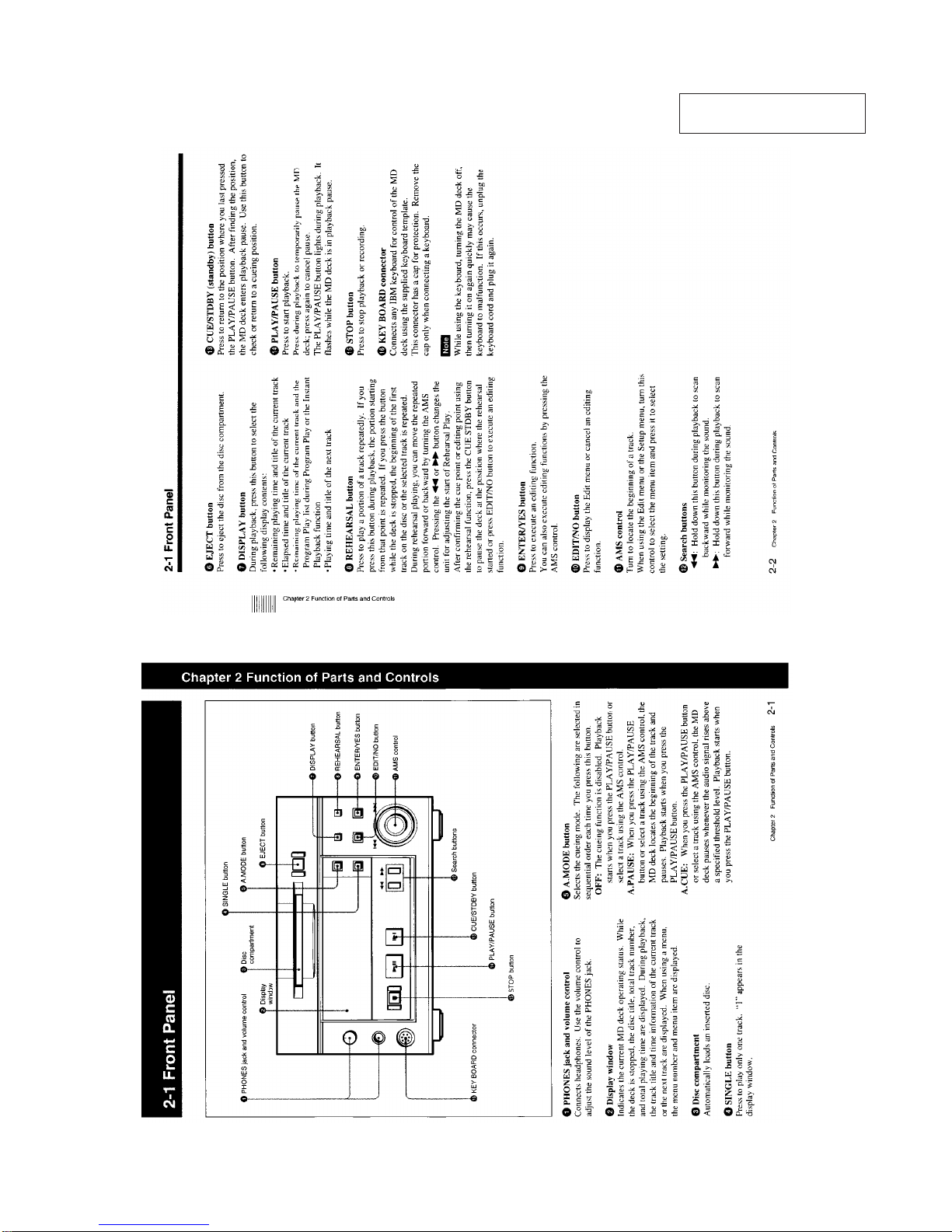
2-1. Front Panel .......................................................................... 5
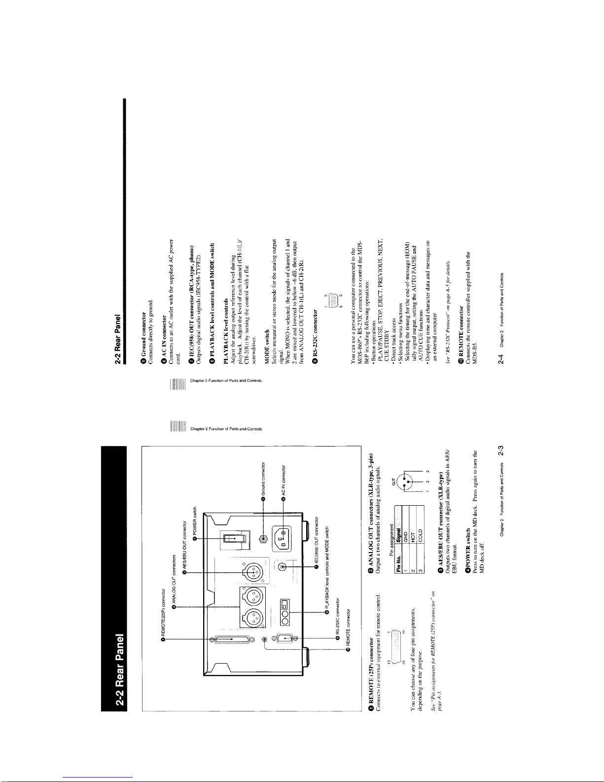
2-2. Rear Panel............................................................................ 6
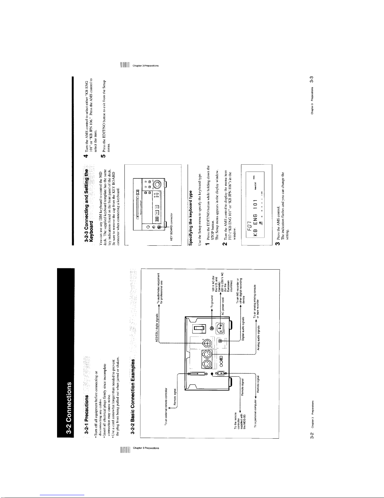
3-2. Connections ......................................................................... 7
3-4. Setting the Analog Output Reference Levels ...................... 8
4-1. Overview of Playback Procedures ...................................... 8
4-2. Playback Procedures............................................................ 9
4-3. Locating a Track ................................................................ 10
4-4. Display Information During Playback .............................. 11
4-5. Playing Tracks Repeatedly ................................................ 11
4-6. Program Play ..................................................................... 12
4-7. Playing Tracks in Random Order (Shuffle Play)............... 13
4-8. Starting Playback Instantly (Multi-Access Function) ....... 13
4-9. Varying the Playback Speed (Variable-Speed Playback) .. 14
4-10. Error Checking .................................................................. 15
5-1. Overview of Editing Functions ......................................... 15
5-2. Erasing Tracks (Erase Function) ....................................... 16
5-3. Dividing a Recorded Track (Divide Function).................. 17
5-4. Combining Recorded Tracks (Combine Function) ........... 18
5-5. Moving Recorded Tracks (Move Function) ...................... 18
5-6. Editing Titles ..................................................................... 19
5-7. Marking the Cue Point ...................................................... 20
5-8. Trimming ........................................................................... 21
6-1. The Overview of the Setup Menu ..................................... 23
6-2. Setting Up for Timer-Activated Function.......................... 23
6-3. Setting the Playback Resume Mode .................................. 24
232C Interface ................................................................... 24
6-5. Setting the Auto Cue Function .......................................... 25
6-6. Setting the Rehearsal Playback Function .......................... 25
6-7. Setting the EOM Function................................................. 26
6-8. Reading the Hours Meter .................................................. 26
6-9. Disabling the Buttons While Controlling Remotely ......... 27
7-1. Cleaning and Reset Switch................................................ 27
7-2. Display Messages .............................................................. 28
Menu Item List ............................................................................ 28
2. DISASSEMBLY
2-1. Case and Front Panel Assembly ........................................ 29
2-2. Back Panel ......................................................................... 29
2-3. Mechanism Deck ............................................................... 30
2-4. Slider ................................................................................. 30
2-5. Base Unit (MBU-2BLP), Loading MotorAssembly......... 31
2-6. Slider Assembly Mounting ................................................ 31
3.TEST MODE
3-1. Setting the Test Mode ........................................................ 32
3-2. Exiting the Test Mode ....................................................... 32
3-3. Basic Operations of the Test Mode ................................... 32
3-4. Selecting the Test Mode .................................................... 32
3-4-1. Operating the Continuous Playback Mode .................. 32
3-4-2. Non-Volatile Memory Mode........................................ 32
3-5. Functions of Other Buttons ............................................... 33
3-6. Test Mode Displays ........................................................... 33
3-7. Meanings of Other Displays.............................................. 33
3-8. Precautions for Use of Test Mode ..................................... 33