Sony DSX-A410BT User manual

SERVICE MANUAL
Sony Video & Sound Products Inc.
USB Player section
Interface: USB (Full-speed)
Maximum current: 1 A
Maximum number of recognizable folders and les:
Folders (albums): 256
Files (tracks) per folder: 256
Compatible Android Open Accessory protocol
(AOA): 2.0
Corresponding codec:
MP3 (.mp3)
Bit rate: 8 kbps - 320 kbps (Supports VBR
(Variable Bit Rate))
Sampling rate: 16 kHz - 48 kHz
WMA (.wma)
Bit rate: 32 kbps - 192 kbps (Supports VBR
(Variable Bit Rate))
Sampling rate: 32 kHz, 44.1 kHz, 48 kHz
FLAC (.ac)
Bit depth: 16 bit, 24 bit
Sampling rate: 44.1 kHz, 48 kHz
Power amplier section
Output: Speaker outputs
Speaker impedance: 4 – 8
Maximum power output: 55 W × 4 (at 4 )
General
Outputs:
Audio outputs terminal (REAR, SUB)
Power antenna (aerial)/Power amplier control
terminal (REM OUT)
Inputs:
Remote controller input terminal
Antenna (aerial) input terminal
AUX input jack (stereo mini jack)
USB port
Power requirements: 12 V DC car battery (negative
ground (earth))
Rated current consumption: 10 A
Dimensions:
Approx. 178 mm × 50 mm × 119 mm
(7 1
/8in × 2 in × 4 3/4in) (w/h/d)
Mounting dimensions:
Approx. 182 mm × 53 mm × 102 mm
(7 1
/4in × 2 1/8in × 4 1
/8in) (w/h/d)
Mass: Approx. 0.7 kg (1 lb 9 oz)
Package contents:
Main unit (1)
Parts for installation and connections (1 set)
Design and specications are subject to change
without notice.
Tuner section
(A410BT: AEP, UK)
FM
Tuning range:
When [AREA] is set to [EUROPE]:
87.5 MHz – 108.0 MHz
When [AREA] is set to [RUSSIA]:
FM1/FM2: 87.5 MHz – 108.0 MHz
(at 50 kHz step)
FM3: 65 MHz – 74 MHz (at 30 kHz step)
Antenna (aerial) terminal:
External antenna (aerial) connector
Intermediate frequency:
When [AREA] is set to [EUROPE]:
FM CCIR: -1,956.5 kHz to -487.3 kHz and
+500.0 kHz to +2,095.4 kHz
When [AREA] is set to [RUSSIA]:
FM CCIR: -1,956.5 kHz to -487.3 kHz and
+500.0 kHz to +2,095.4 kHz
FM OIRT: -1,815.6 kHz to -943.7 kHz and
+996.6 kHz to +1,776.6 kHz
Usable sensitivity: 7 dBf
Selectivity: 75 dB at 400 kHz
Signal-to-noise ratio: 73 dB
Separation: 50 dB at 1 kHz
Frequency response: 20 Hz – 15,000 Hz
MW/LW
Tuning range:
MW: 531 kHz – 1,602 kHz
LW: 153 kHz – 279 kHz
Antenna (aerial) terminal:
External antenna (aerial) connector
Sensitivity: MW: 26 V, LW: 50 V
Wireless Communication
Communication System:
BLUETOOTH Standard version 3.0
Output:
BLUETOOTH Standard Power Class 2
(radiated -9 dBm) (A410BT: AEP, UK)
(Max. +4 dBm) (A410BT:E, AR, IND, AUS/A415BT)
Maximum communication range:
Line of sight approx. 10 m (33 ft)*1
Frequency band:
2.4 GHz band (2.4000 GHz – 2.4835 GHz)
Modulation method: FHSS
Compatible BLUETOOTH Proles*2:
A2DP (Advanced Audio Distribution Prole) 1.3
AVRCP (Audio Video Remote Control Prole) 1.3
HFP (Handsfree Prole) 1.6
PBAP (Phone Book Access Prole)
SPP (Serial Port Prole)
Corresponding codec:
SBC (.sbc), AAC (.m4a)
*1 The actual range will vary depending on factors such
as obstacles between devices, magnetic elds
around a microwave oven, static electricity,
reception sensitivity, antenna (aerial)’s performance,
operating system, software application, etc.
*2 BLUETOOTH standard proles indicate the purpose
of BLUETOOTH communication between devices.
NFC Communication (A410BT: AEP, UK)
Frequency band and maximum power spec
NFC: 13.56 MHz < 60 dBA/m at 10 m
FOR THE CUSTOMERS IN THE USA. NOT
APPLICABLE IN CANADA, INCLUDING IN THE
PROVINCE OF QUEBEC.
POUR LES CLIENTS AUX ÉTATS-UNIS. NON
APPLICABLE AU CANADA, Y COMPRIS LA
PROVINCE DE QUÉBEC.
AUDIO POWER SPECIFICATIONS
CTA2006 Standard
Power Output: 20 Watts RMS × 4 at 4
Ohms < 1% THD+N
SN Ratio: 80 dBA
(reference: 1 Watt into 4 Ohms)
(A410BT: E, AR, IND, AUS)
FM
Tuning range:
87.5 MHz – 108.0 MHz (at 50 kHz step)
87.5 MHz – 108.0 MHz (at 100 kHz step)
87.5 MHz – 107.9 MHz (at 200 kHz step)
For Argentine models: 87.5 MHz – 107.9 MHz
FM tuning step (except for Argentine models):
50 kHz/100 kHz/200 kHz switchable
Antenna (aerial) terminal:
External antenna (aerial) connector
Intermediate frequency:
FM CCIR: -1,956.5 kHz to -487.3 kHz and
+500.0 kHz to +2,095.4 kHz
Usable sensitivity: 7 dBf
Selectivity: 75 dB at 400 kHz
Signal-to-noise ratio: 73 dB
Separation: 50 dB at 1 kHz
Frequency response: 20 Hz – 15,000 Hz
AM
Tuning range:
531 kHz – 1,602 kHz (at 9 kHz step)
530 kHz – 1,710 kHz (at 10 kHz step)
For Argentine models: 530 kHz – 1,710 kHz
AM tuning step (except for Argentine models):
9 kHz/10 kHz switchable
Antenna (aerial) terminal:
External antenna (aerial) connector
Sensitivity: 26 µV
(A415BT)
(A415BT)
FM
Tuning range: 87.5 MHz – 107.9 MHz
Antenna (aerial) terminal:
External antenna (aerial) connector
Intermediate frequency:
FM CCIR: -1,956.5 kHz to -487.3 kHz and
+500.0 kHz to +2,095.4 kHz
Usable sensitivity: 7 dBf
Selectivity: 75 dB at 400 kHz
Signal-to-noise ratio: 73 dB
Separation: 50 dB at 1 kHz
Frequency response: 20 Hz – 15,000 Hz
AM
Tuning range: 530 kHz – 1,710 kHz
Antenna (aerial) terminal:
External antenna (aerial) connector
Sensitivity: 26 µV
SiriusXM input terminal (A415BT)
Remote commander (1): RM-X231 (A410BT:E, AR, IND,
AUS/A415BT)
SPECIFICATIONS
9-896-416-02
2017J33-1
© 2017.10
US Model
Canadian Model
PX Model
DSX-A415BT
AEP Model
UK Model
E Model
Australian Model
DSX-A410BT
Ver. 1.1 2017.10
• This model is not equipped with a mechanism deck.
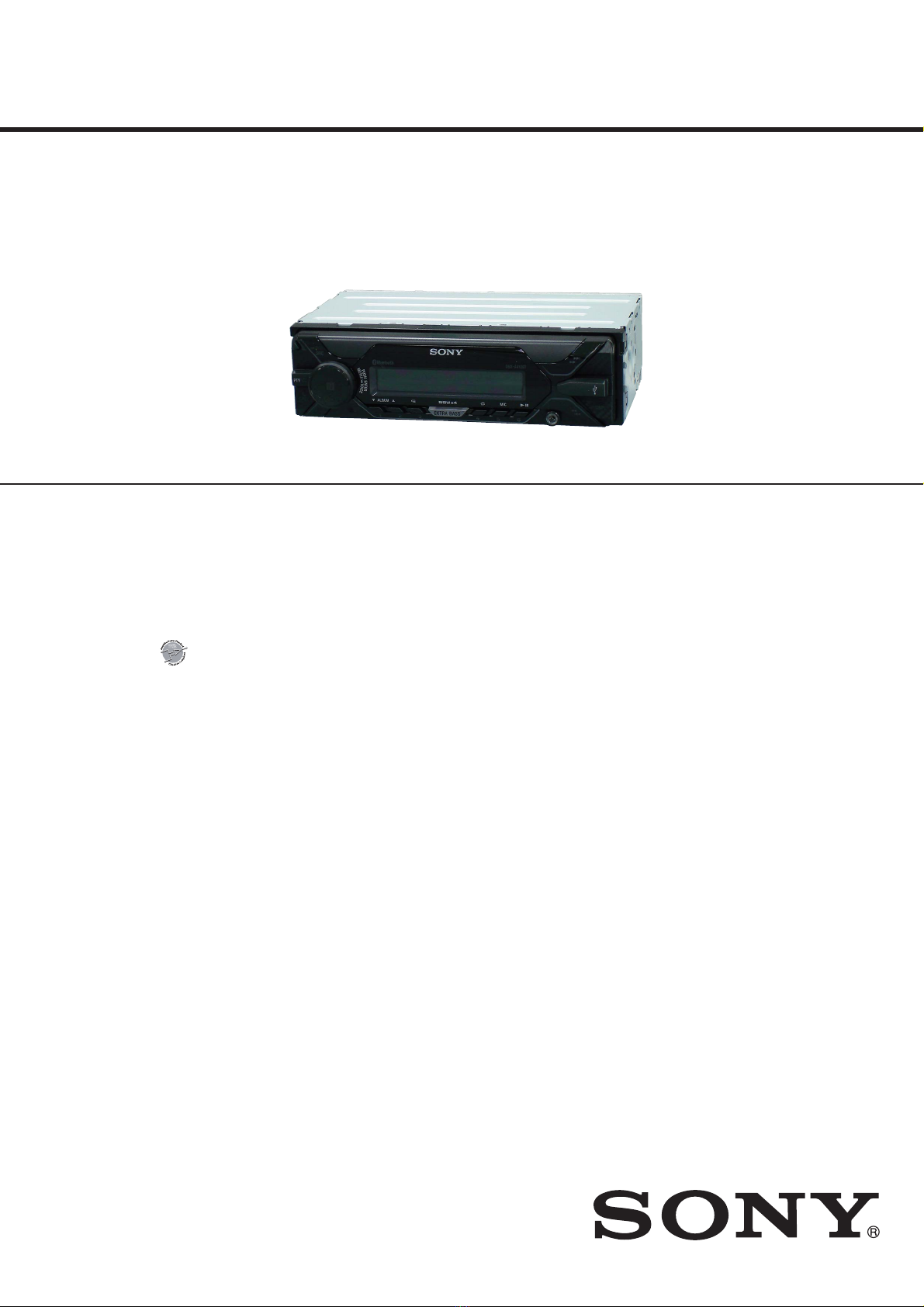
DSX-A410BT/A415BT
Photo: DSX-A410BT
US, CND, E, AR, IND, AUS and PX models
FM/AM DIGITAL MEDIA PLAYER
AEP and UK models
FM/MW/LW DIGITAL MEDIA PLAYER

DSX-A410BT/A415BT
2
1. SERVICING NOTES ............................................. 3
2. GENERAL .................................................................. 17
3. DISASSEMBLY
3-1. Disassembly Flow........................................................... 23
3-2. Mini Fuse (Blade Type), Cover ...................................... 23
3-3. Sub Panel Complete Assy ............................................... 24
3-4. Sub Panel Assy, Microphone .......................................... 25
3-5. Chassis, MAIN Board..................................................... 25
4. TEST MODE ............................................................ 26
5. DIAGRAMS
5-1. Block Diagram - MAIN Section -................................... 27
5-2. Block Diagram
- PANEL/POWER SUPPLY Section -............................ 28
5-3. Schematic Diagram - MAIN Board (1/3) -..................... 29
5-4. Schematic Diagram - MAIN Board (2/3) -..................... 30
5-5. Schematic Diagram - MAIN Board (3/3) -..................... 31
5-6. Printed Wiring Board
- MAIN Board (Component Side) -................................ 32
5-7. Printed Wiring Board
- MAIN Board (Conductor Side) -.................................. 33
6. EXPLODED VIEW ................................................. 39
7. ELECTRICAL PARTS LIST .............................. 40
Accessories are given in the last of the electrical parts list.
TABLE OF CONTENTS
SiriusXM ConnectVehicleTuner and Subscription
soldseparately.
www.siriusxm.com
Sirius, XM and all related marks and logos are
trademarks of Sirius XM Radio Inc.All rights
reserved.
The Bluetooth® word mark and logos are registered
trademarks owned by the Bluetooth SIG, Inc.and
any use of suchmarks by Sony Corporation is under
license. Other trademarks and trade names are
those of their respective owners.
The N-Mark is atrademark or registered trademark
of NFC Forum, Inc.in the United States and in other
countries.
Windows Media is either aregistered trademark or
trademark of Microsoft Corporation in the United
States and/or other countries.
This productis protected by certain intellectual
property rights of Microsoft Corporation. Use or
distribution of suchtechnology outside of this
productis prohibited without alicense from
Microsoft or an authorized Microsoft subsidiary.
iPhone, iPod, iPod classic,iPod nano, iPod touch,
and Siri are trademarks of AppleInc., registered in
the U.S. and other countries. App Store is aservice
mark of AppleInc.
MPEG Layer-3 audio coding technology and patents
licensed from Fraunhofer IIS and Thomson.
Pandora®,the Pandora® logo, and the Pandora®
trade dress are trademarks or registered
trademarks of Pandora Media, Inc., used with
permission.
Google, GooglePlay and Android are trademarks of
GoogleInc.
Copyrights
libFLAC
Copyright (C) 2000-2009 Josh Coalson
Copyright (C) 2011-2013Xiph.Org Foundation
Redistribution and use in sourceand binary forms,
with or without modication, are permitted
provided that the following conditions are met:
Redistributions of sourcecode must retain the
above copyright notice, this list of conditions and
the following disclaimer.
Redistributions in binary form must reproduce
the above copyright notice, this list of conditions
and the following disclaimer in the
documentation and/or other materialsprovided
with the distribution.
Neither the name of the Xiph.org Foundation nor
the names of its contributors may be usedto
endorse or promote products derived from this
software without specic prior written
permission.
THIS SOFTWARE IS PROVIDED BY THE COPYRIGHT
HOLDERS AND CONTRIBUTORS “AS IS” AND ANY
EXPRESS OR IMPLIED WARRANTIES, INCLUDING,
BUT NOT LIMITED TO, THE IMPLIED WARRANTIESOF
MERCHANTABILITY AND FITNESS FOR A
PARTICULAR PURPOSE ARE DISCLAIMED. IN NO
EVENT SHALL THE FOUNDATION OR CONTRIBUTORS
BE LIABLE FOR ANY DIRECT,INDIRECT,INCIDENTAL,
SPECIAL, EXEMPLARY,OR CONSEQUENTIAL
DAMAGES (INCLUDING, BUT NOT LIMITED TO,
PROCUREMENT OF SUBSTITUTEGOODS OR
SERVICES; LOSS OF USE, DATA, OR PROFITS; OR
BUSINESS INTERRUPTION) HOWEVER CAUSED AND
ON ANY THEORY OF LIABILITY,WHETHER IN
CONTRACT,STRICT LIABILITY,OR TORT (INCLUDING
NEGLIGENCE OR OTHERWISE) ARISING IN ANY WAY
OUT OF THE USE OF THIS SOFTWARE, EVEN IF
ADVISED OF THE POSSIBILITY OF SUCH DAMAGE.
NOTES ON CHIP COMPONENT REPLACEMENT
• Never reuse a disconnected chip component.
• Notice that the minus side of a tantalum capacitor may be dam-
aged by heat.

DSX-A410BT/A415BT
3
SECTION 1
SERVICING NOTES
The SERVICING NOTES contains important information for servicing. Be sure to read this section before repairing the unit.
UNLEADED SOLDER
Boards requiring use of unleaded solder are printed with the lead-
free mark (LF) indicating the solder contains no lead.
(Caution: Some printed circuit boards may not come printed with
the lead free mark due to their particular size)
: LEAD FREE MARK
Unleaded solder has the following characteristics.
• Unleaded solder melts at a temperature about 40 °C higher
than ordinary solder.
Ordinary soldering irons can be used but the iron tip has to be
applied to the solder joint for a slightly longer time.
Soldering irons using a temperature regulator should be set to
about 350 °C.
Caution: The printed pattern (copper foil) may peel away if
the heated tip is applied for too long, so be careful!
• Strong viscosity
Unleaded solder is more viscous (sticky, less prone to flow)
than ordinary solder so use caution not to let solder bridges
occur such as on IC pins, etc.
• Usable with ordinary solder
It is best to use only unleaded solder but unleaded solder may
also be added to ordinary solder.
REPLACING THE LITHIUM BATTERY OF THE REMOTE
COMMANDER
(DSX-A410BT: E, AR, IND, AUS/DSX-A415BT)
Under normal conditions, the battery will last
approximately 1 year. (The service life may be
shorter, depending on the conditions of use.)
When the battery becomes weak, the range of the
remote commander becomes shorter.
CAUTION
Danger of explosion if battery is incorrectly
replaced. Replaced only with the same or
equivalent type.
Notes on the lithium battery
ˎKeep the lithium battery out of the reach of children.
Should the battery be swallowed, immediately
consult a doctor.
ˎWipe the battery with a dry cloth to ensure a good
contact.
ˎBe sure to observe the correct polarity when installing
the battery.
ˎDo not hold the battery with metallic tweezers,
otherwise a short-circuit may occur.
+ side up
DESTINATION ABBREVIATIONS
The following abbreviations for model destinations are used in this
service manual.
• Abbreviations
AEP : European area, East European area and CIS area mod-
els
AR : Latin American area (Argentina, Uruguay) model
AUS : Oceania area (Australia, New Zealand) model
CND : Canadian and Latin American area (Puerto Rico) models
E : Latin American area (Except for Puerto Rico), Middle
Eastern, Southeast Asian area (Except for India), East
Asian area and African models
IND : Indian model
MODEL IDENTIFICATION
Distinguish by the Part No. of model number label that is stuck on
the bottom of main unit.
Model number label
Part No.
(Except AEP, UK)
Part No.
(AEP, UK)
Part No. Destination
4-698-228-0[] DSX-A410BT: E, AUS models (E)
4-698-229-0[] DSX-A410BT: AR model (AR)
4-698-231-0[] DSX-A410BT: AEP, UK models (EUR)
4-698-233-0[] DSX-A410BT: IND model (IN)
4-698-234-0[] DSX-A415BT: US, CND, PX models (UC)
NOTE OF REPLACING THE MAIN BOARD
When replacing the MAIN board, there are notes and necessary to
perform a few works. Be sure to refer to the following.
Note of replace simultaneous:
When the MAIN board is replaced, be sure to replace the knob
(VOL) assy simultaneously.
Required works:
• Destination setting (refer to “DESTINATION SETTING METH-
OD” on page 4)
• Bluetooth information writing (refer to “BLUETOOTH IN-
FORMATION WRITING METHOD” on page 8)
• Initializing (refer to “IMPORTANT NOTE OF INITIALIZ-
ING” on page 6)
Operation check works:
• BLUETOOTH FUNCTION CHECKING METHOD USING
A SMARTPHONE OR CELLULAR PHONE (page 7)
• OPERATION CHECK OF THE NFC AFTER COMPLETING
THE REPAIRS (page 6)
• OPERATION CHECK OF THE USB (page 5)
NOTE OF REPLACING THE FRONT PANEL ASSY OR
THE KNOB (VOL) ASSY
When replacing the front panel assy or the knob (VOL) assy, it is
necessary to perform a few works. Be sure to refer to the follow-
ing.
Required works:
• Bluetooth information writing (refer to “BLUETOOTH IN-
FORMATION WRITING METHOD” on page 8)
• Affix the label (serial number) to the front panel ASSY and
the main unit, and delivery of notification to customer (refer to
“AFFIXING OF LABEL (SERIAL NUMBER)” on page 13)
Note: Affix of label and delivery of notification to customers is only when
replacing the front panel assy. When replacing the knob (VOL) assy
to not necessary.
Operation check works:
• BLUETOOTH FUNCTION CHECKING METHOD USING
A SMARTPHONE OR CELLULAR PHONE (page 7)
• OPERATION CHECK OF THE NFC AFTER COMPLETING
THE REPAIRS (page 6)
Ver. 1.1

DSX-A410BT/A415BT
4
DESTINATION SETTING METHOD
When the MAIN board or system controller (IC501) is replaced,
the destination setting is necessary.
1. Destination Setting
Set destination according to the procedure below.
1-1. Setting the Destination Code
1. In the state of source off (the clock is displayed on the liquid
crystal display), enter the test mode by pressing the buttons in
order of the [ 4] →[MIC 5] →[u6] (press only the [u6]
button for two seconds).
Clock display
Note 1: There is displayed “1:00 AM”, depending on the destination.
2. In the state in which the software main version is displayed on
the liquid crystal display (refer to the following figure), enter
the destination setting mode by pressing the buttons in order
of the [>M] →[m.] →[PUSH ENTER/MENU/
VOICE].
(Displayed characters/values in the following figure are ex-
ample)
Software main version
3. Input the alphanumeric character of 6 digits displayed on the
liquid crystal display, and execute the destination setting.
Note 2: The displayed contents of the following figure is an example. The
destination code is different depending on the destination of the
product.
Note 3: Refer to the following “1-3. Entering the Destination Code” for
operation method.
Destination code
6 digits
4. The resetting operation is executed by pressing the [ OFF
SRC] button for 1 second after the setting ends, and the unit
returns to the normal condition.
Display after reset
Note 4: There is displayed “1:00 AM”, depending on the destination.
1-2. Display in Destination Setting Mode
Note: The displayed contents of the following figure is an example. The
destination code is different depending on the destination of the
product.
Destination code
OP0OP1OP2OP3OP4OP5
6 digits
1-3. Entering the Destination Code
• Method of operation by main unit
1. Rotate the control dial, and select the alphanumeric character
of “0 to F”.
2. The digit advances by pressing the [PUSH ENTER/MENU/
VOICE] or [>M] button.
The digit returns by pressing the [ MODE] or [m.] but-
ton.
3. The setting is completed by pressing the [PUSH ENTER/
MENU/ VOICE] button at the state of cursor position of
“OP0”, then the display turns off, the initialization operation
is done, and the display returns to the clock display.
• Method of operation by remote commander
(DSX-A410BT: E, AR, IND, AUS/DSX-A415BT)
Note: The model to which the remote commander is not attached can
also be operated by using the optional remote commander.
1. Press the [V] or [v] button, and select the alphanumeric char-
acter of “0 to F”.
2. The digit advances by pressing the [b] or [ENTER] button.
The digit returns by pressing the [B] button.
3. The setting is completed by pressing the [ENTER] button at
the state of cursor position of “OP0”, then the display turns off,
the initialization operation is done, and the display returns to
the clock display.
Ver. 1.1

DSX-A410BT/A415BT
5
1-4. Destination Code
Model Destination OP5 OP4 OP3 OP2 OP1 OP0
DSX-A410BT
AEP, UK 0 4 9 0 5 1
E, AUS 3 4 B 8 5 0
AR 34B853
IND 149850
DSX-A415BT US, CND, PX 0 7 9 0 7 2
2. Confirmation After Destination Setting
Execute the following operation after completing the destination
setting, and confirm a correct destination was set.
Destination setting checking method:
1. In the state of source off (the clock is displayed on the liquid
crystal display), enter the test mode by pressing the buttons in
order of the [ 4] →[MIC 5] →[u6] (press only the [u6]
button for two seconds).
Clock display
Note 1: There is displayed “1:00 AM”, depending on the destination.
2. In the state in which the software main version is displayed
on the liquid crystal display (refer to the following figure),
enter the destination setting value display mode by pressing
the [ SCRL DSPL] button three times (software main version
→software DSP version →Bluetooth address →destination
code).
(Displayed characters/values in the following figure are ex-
ample)
Software main version
3. Confirm the alphanumeric character of 6 digits on the liquid
crystal display is a value correctly input.
Note 2: The displayed contents of the following figure is an example. The
destination code is different depending on the destination of the
product.
Destination code
OP0OP1OP2OP3OP4OP5
6 digits
4. The resetting operation is executed by pressing the [ OFF
SRC] button for 1 second after the confirming ends, and the
unit returns to the normal condition.
Display after reset
Note 3: There is displayed “1:00 AM”, depending on the destination.
NOTE OF REPLACING THE ANT001, CP001, IC001,
IC602 AND IC1301 ON THE MAIN BOARD
ANT001, CP001, IC001, IC602 and IC1301 on the MAIN board
cannot replace with single. When these parts are damaged, replace
the complete mounted board.
NOTE OF REPLACING THE KEY BOARD
The KEY board does not repair the board. When the KEY board
is defective, replace the whole of front panel assy (Ref. No. FP1)
including the KEY board.
OPERATION CHECK OF THE USB
Connect a USB device to this unit for checking the USB operation
of this unit.
Refer to the support site written in the operating instructions for
the details about the compatibility of a USB device.
CANCELING THE DEMO MODE
You can cancel the demonstration display which
appears when the source is off and the clock is
displayed.
1Press MENU, rotate the control dial to
select [GENERAL], then press it.
2Rotate the control dial to select [SET
DEMO], then press it.
3Rotate the control dial to select [SET
DEMO-OFF], then press it.
The setting is complete.
4Press (back) twice.
The display returns to normal reception/play
mode.
CLEANING THE CONNECTORS
The unit may not function properly if the
connectors between the unit and the front panel
are not clean. In order to prevent this, detach the
front panel (page 6) and clean the connectors with
a cotton swab. Do not apply too much force.
Otherwise, the connectors may be damaged.
Notes
ˎFor safety, turn off the ignition before cleaning the
connectors, and remove the key from the ignition
switch.
ˎNever touch the connectors directly with your fingers
or with any metal device.
and clean the connectors with
RESETTING THE UNIT
Before operating the unit for the first time, or after
replacing the car battery or changing connections,
you must reset the unit.
1Press DSPL and (back)/MODE for
more than 2 seconds.
Note
Resetting the unit will erase the clock setting and some
stored contents.
SETTING THE AREA/REGION (AEP, UK only)
After resetting the unit, the area/region setting
display appears.
1Press ENTER while [SET AREA] is
displayed.
The area/region currently set appears.
2Rotate the control dial to select [EUROPE]
or [RUSSIA], then press it.
3Rotate the control dial to select [YES] or
[NO], then press it.
If the setting area/region is changed, the unit is
reset, then the clock is displayed.
This setting can be configured in the general setup
menu
(p
a
g
e19
)
.
.
Ver. 1.1

DSX-A410BT/A415BT
6
OPERATION CHECK OF THE NFC AFTER COMPLET-
ING THE REPAIRS
After completing the repairs of this unit, follow the procedure below
to check normal operation of the NFC.
Note: After checking of NFC operation, be sure to delete the pairing infor-
mation before returning this unit to the customer.
For deleting method of the pairing information, refer to “IMPOR-
TANT NOTE OF INITIALIZING”.
By touching the control dial on the unit with an
NFC* compatible smartphone, the unit is paired and
connected with the smartphone automatically.
* NFC (Near Field Communication) is a technology
enabling short-range wireless communication
between various devices, such as mobile phones and
IC tags. Thanks to the NFC function, data
communication can be achieved easily just by
touching the relevant symbol or designated location
on NFC compatible devices.
For a smartphone with Android OS 4.0 or lower
installed, downloading the app “NFC Easy Connect”
available at Google Play™ is required. The app may
not be downloadable in some countries/regions.
1Activate the NFC function on the
smartphone.
For details, refer to the operating instructions
supplied with the smartphone.
2Touch the N-Mark part of the unit with
the N-Mark part of the smartphone.
Make sure that lights up on the display of the
unit.
To disconnect using NFC
Touch the N-Mark part of the unit with the N-Mark
part of the smartphone again.
Notes
ˎWhen making the connection, handle the
smartphone carefully to prevent scratches.
ˎOne-touch connection is not possible when the unit is
already connected to another NFC compatible device.
In this case, disconnect the other device, and make
connection with the smartphone again.
Connecting with a Smartphone using
One-touch connection (NFC)
IMPORTANT NOTE OF INITIALIZING
The purpose of “Bluetooth Initialize” is to initialize the Bluetooth
connection history (HF/Audio Streaming). (To delete the device
information for the devices that you connected to when searching,
etc.)
When the MAIN board is replaced, it is necessary to initialize this
unit.
Refer to the following, initialize this unit.
Note: Phonebook data and dialed/received call history can be deleted by
executing “Bluetooth Initialize”.
Procedure:
1. In the state of source off (the clock is displayed on the liquid
crystal display), press the [PUSH ENTER/MENU/ VOICE]
button.
2. Rotate the control dial, and select the “BLUETOOTH”.
3. Press the [PUSH ENTER/MENU/ VOICE] button.
4. Rotate the control dial, and select the “SET BT INIT”.
5. Press the [PUSH ENTER/MENU/ VOICE] button, and the
message “SET INIT-NO” is displayed on the liquid crystal dis-
play.
6. Rotate the control dial clockwise, and the message “SET INIT-
YES” is displayed on the liquid crystal display.
7. Press the [PUSH ENTER/MENU/ VOICE] button.
8. When “Bluetooth Initialize” is completed, the message
“COMPLETE” is displayed on the liquid crystal display for a
moment.
9. Press the [ MODE] button twice, and return to the state of
source off (the clock is displayed on the liquid crystal display).

DSX-A410BT/A415BT
7
6. Bluetooth Phone (Hands Free) Function Check
1. Search for this unit from the Bluetooth device (smartphone or
cellular phone), and confirm whether this unit (model name) is
displayed.
2. Search for the distance of this unit and the Bluetooth device
(smartphone or cellular phone) about 5 m apart.
Confirm whether the this unit is displayed after it searches.
3. Do the pairing of the smartphone or cellular phone and this
unit.
(If the input of the passkey is required, to enter the “0000”)
4. Connect the smartphone or cellular phone with this unit, and
confirm the “HF” icon ( ) is lights.
5. Confirm the connection continues even if the distance of the
smartphone or cellular phone and this unit is separated by
about 5 m.
6. Set this unit except the “BT PHONE” source, and call the
smartphone or cellular phone connected with this unit.
Confirm the automatic change of this unit into “BT PHONE”
source, and the change into the screen for incoming calls.
Confirm the ring tone is heard from the front speaker.
7. Take a phone call (press the [ CALL] button), and start a
conversation.
Confirm the other person voice is heard from the speaker.
Speak toward an internal microphone at the following condi-
tion, and confirm the other party hears its voice.
Compare the sound quality with a normal set. Confirm that
there is no big difference.
8. Turn on ACC from off, and confirm whether this unit connects
Bluetooth with the smartphone or cellular phone again.
Note: Depending on the smartphone or cellular phone, it might not recon-
nect automatically when ACC is turned on.
7. Bluetooth Audio Function Check
Note 1: Depending on the connecting BT Audio device, track information
(e.g. track name, playback time) can be on display.
If the device doesn’t support AVRCP1.3, or, if AVRCP1.3 feature
of the device has not been validated with this unit, the track infor-
mation won’t be shown.
Even if there is no track information on display during playback
of an AVRCP1.3 device, it is not a failure of this unit.
1. Connect the Bluetooth audio device (or smartphone, cellular
phone with Bluetooth audio function) with this unit, and con-
firm the “Audio Streaming” icon ( ) is lights.
2. Playback the Bluetooth audio. Confirm the sound is emitted
from this unit when this unit is switched to “BT AUDIO”
source.
3. Confirm whether Bluetooth audio can be controlled by operat-
ing this unit (the [>M], [m.] and [u6] buttons opera-
tion).
Note 2: Varies depending on the connected Bluetooth audio device.
8. What to Do after Checking
• After checking, this unit to execute initialization (refer to “IM-
PORTANT NOTE OF INITIALIZING” on page 6).
(Connected device information is deleted)
BLUETOOTH FUNCTION CHECKING METHOD USING
A SMARTPHONE OR CELLULAR PHONE
1. Required Equipment
• This unit to be tested
• Bluetooth compatible smartphone or cellular phone
• Bluetooth audio devices (SONY NWZ-A826, or select from
connectable smartphone, cellular phones or audio devices list)
• Speaker connection (at least Front L/R ch)
• DC power supply (12 V)
2. Preparation
• Confirm the setting of this unit and note down it.
• Press the [PUSH ENTER/MENU/ VOICE] button, rotate the
control dial to select, and determine in the following order,
then confirm that the Bluetooth signal icon ( ) is flashing.
“BLUETOOTH” →“SET PAIRING” →“SET DEVICE 1”
(or “SET DEVICE 2”)
• Turn on the Bluetooth function of the smartphone or cellular
phone.
3. Test Environment
• No other Bluetooth device is making a communication in the
periphery (within 20 m).
• No other this unit are supplied with electric power.
• There are no two or more wireless LAN access points in the
periphery (with 50 m) (one is OK).
• The set should be tested in a place such as a meeting room, free
from ambient noise.
• The speaker at the far end should be in a place such as another
meeting room separated acoustically.
4. Setting
Install this unit on the desktop.
Speaker
Approx. 50 cm
Unit
Tester
Approx. 80 cm
5. Precautions
Beware of the following points when conducting the
talking test:
• There is no fault if a talking can be made by adjusting ap-
propriately the volume of the telephone of the other party and
the smartphone or cellular phone connected through the Blue-
tooth, besides the setup of this unit.
• The speaker’s voice will become loud naturally if the periph-
ery is noisy, or become low if quiet (even though the speaker
intents to talk on the same volume level).
• The speaker’s voice will become loud naturally if the other
party’s voice is loud.

DSX-A410BT/A415BT
8
BLUETOOTH INFORMATION WRITING METHOD
When the following parts are replaced, the writing of Bluetooth
information is necessary.
Applicable parts:
• MAIN board and knob (VOL) assy (Exploded view: Ref. No.
4 and Ref. No. NFC1)
Note: When the MAIN board is replaced, it is necessary to replace knob
(VOL) assy simultaneously.
• Knob (VOL) assy (Exploded view: Ref. No. NFC1)
• Front panel assy (Including knob (VOL) assy) (Exploded
view: Ref. No. FP1)
Write the Bluetooth information according to the procedure below.
Preparation:
• Windows PC
• NFC compatible smartphone that installed the file manager ap-
plication (ASTRO File Manager, File Expert, etc.)
• USB cable for the smartphone
• NFC Tag Data Writing Application
(Application name: ePF_NFCtagWriter_gm.apk)
Note: Confirm the method of obtaining the NFC Tag Data Writing Ap-
plication and its latest version with the each service headquarters.
Notes on the use of the NFC Tag Data Writing Applica-
tion
• The NFC Tag Data Writing Application is updated on an ir-
regular basis.
Always use the latest version of the NFC Tag Data Writing
Application.
To confirm the version of the NFC Tag Data Writing Appli-
cation, refer to “Checking the Version of the NFC Tag Data
Writing Application” on page 9.
• Be sure to uninstall older versions of the NFC Tag Data
Writing Application before installing the latest version.
• There are multiple types of the NFC Tag Data Writing Ap-
plication. If multiple NFC Tag Data Writing Applications
are installed on a smartphone, do not launch more than one
at the same time.
• The NFC Tag Data Writing Application varies depending on
your model.
Be sure to use the NFC Tag Data Writing Application that
supports your model.
Use of NFC Tag Data Writing Applications that do not sup-
port your model is strictly prohibited.
1. Installing the NFC Tag Data Writing Application for
the Servicing
Install the NFC Tag Data Writing Application on the smart-
phone for writing of Bluetooth information.
If the NFC Tag Data Writing Application is already installed,
confirm the following.
• Be absolutely sure that the NFC Tag Data Writing Ap-
plication supports your model.
• Confirm that the NFC Tag Data Writing Application is
the latest version.
(Refer to “Checking the Version of the NFC Tag Data
Writing Application” on page 9)
Procedure:
1. Prepare the NFC Tag Data Writing Application on the PC.
Note: Be absolutely sure that the NFC Tag Data Writing Application sup-
ports your model.
2. Connect the smartphone to the PC with the USB cable.
3. Transfer the NFC Tag Data Writing Application to the smart-
phone.
4. When tapping the “Settings” →“Security” on the screen of the
smartphone, check the box “Unknown sources”.
5. Disconnect the smartphone from the PC.
6. Use the file manager application to explore the NFC Tag Data
Writing Application on the smartphone.
7. Click on the NFC Tag Data Writing Application to open
it, and install the NFC Tag Data Writing Application to the
smartphone.
8. When tapping the “Settings” →“Security” on the screen of the
smartphone, uncheck the box “Unknown sources”.
Movies
YouTube Camera
Settings AlbumWALKMAN
Play Store
Browser
Maps
Media Player
Chrome ePF
NFCtagWriter
NFC Tag Data
Writing Application
–
Screen after the installation
for reference –
9. Refer to “Checking the Version of the NFC Tag Data Writing
Application” on page 9, and confirm that the NFC Tag Data
Writing Application is the latest version.

DSX-A410BT/A415BT
9
• Checking the Version of the NFC Tag Data Writing
Application
Procedure:
1. Start the NFC Tag Data Writing Application on the smart-
phone.
2. Tap the “ ” (menu button) or “ ” of the screen of the smart-
phone, then tap the “About” that is displayed on the screen of
the smartphone.
or
3. Check that version of the NFC Tag Data Writing Application
for the servicing is displayed on the screen of the smartphone.
Here version is
displayed
2. Writing the NFC Tag Data
Write the NFC tag data (Bluetooth information) to the NFC mod-
ule in the knob (VOL) assy (Ref. No. NFC1).
Procedure:
1. Check the Bluetooth address (BD_ADDR).
There are following two checking methods.
• How to read from the BT module label
• How to display on the liquid crystal display by the test
mode
How to read from the BT module label:
Set the unit to the state where the BT module on the MAIN
board can be seen.
(Refer to “3. DISASSEMBLY” on page 23 and after)
– MAIN Board (Component Side) –
BT module label
BD_ADDR
(Barcode)
BD_ADDR
48D2242F241A
– Continued on next page –

DSX-A410BT/A415BT
10
How to display on the liquid crystal display by the
test mode:
1In the state of source off (the clock is displayed on the
liquid crystal display), enter the test mode by pressing the
buttons in order of the [ 4] →[MIC 5] →[u6] (press
only the [u6] button for two seconds).
(Displayed characters/values in the following figure are
example)
Software main version
2In the state in which the software main version is displayed
on the liquid crystal display, enter the Bluetooth address
(BD_ADDR) display mode by pressing the [ SCRL
DSPL] button twice (software main version →software
DSP version →Bluetooth address).
(Displayed characters/values in the following figure are
example)
Bluetooth address (BD_ADDR)
Note 1: When pressing the [ SCRL DSPL] button again, the destina-
tion code is displayed on the liquid crystal display, but it is
not necessary to display in this step.
3The resetting operation is executed by pressing the [ OFF
SRC] button for 1 second after the confirming ends, and
the unit returns to the normal condition.
2. Turn on the NFC function of the smartphone.
3. Start the NFC Tag Data Writing Application on the smart-
phone.
4. Tap the “Write” on the screen of the smartphone.
5. Input the Bluetooth Local Name (BL_NAME).
Tap the “List” on the screen of the smartphone and select the
model name of the this unit. If there is not model name of the
this unit on the list, please input the model name with the key-
board on the smartphone.
Bluetooth Local Name
Bluetooth Device Addres
6. Input the Bluetooth address (BD_ADDR).
Input the Bluetooth address (BD_ADDR) that was checked by
step 1 with the keyboard on the smartphone, or tap the “QR”
on the screen of the smartphone and read the barcode with the
camera of the smartphone.
DSX-A410BT
Bluetooth Device Addres
7. Tap the “Write” on the screen of the smartphone, in the state
that unchecked the box “Read-only”.
48D2242F241A
DSX-A410BT
8. Touch the N-mark part of the smartphone to the N-mark part of
the unit.
– Continued on next page –

DSX-A410BT/A415BT
11
9. Check that “Completed!” is displayed on the screen of the
smartphone.
Note 2: When “Completed!” is not displayed on the screen of the smart-
phone, refer to “3. Error Display” on page 12.
10. End the NFC Tag Data Writing Application on the smartphone.
11. Check the operation of connecting with the smartphone by one
touch (NFC).
(Refer to “OPERATION CHECK OF THE NFC AFTER
COMPLETING THE REPAIRS” on page 6)
12. Start the NFC Tag Data Writing Application on the smart-
phone.
13. Tap the “Write” on the screen of the smartphone.
14. Check the box “Read-only” on the screen of the smartphone,
and tap the “Write” on the screen of the smartphone.
48D2242F241A
DSX-A410BT
15. Touch the N-mark part of the smartphone to the N-mark part of
the unit.
16. Check that “Completed!” is displayed on the screen of the
smartphone.
Note 3: When “Completed!” is not displayed on the screen of the smart-
phone, refer to “3. Error Display” on page 12.
17. Tap the “Read” on the screen of the smartphone.
18. Check that “BD_ADDR” on the screen of the smartphone ac-
cords with BD_ADDR written on the BT module label and
“MODE” on the screen of the smartphone is “00 00 (Read-
only)”.
19. End the NFC Tag Data Writing Application on the smartphone.
20. Check the operation of connecting with the smartphone by one
touch (NFC).
(Refer to “OPERATION CHECK OF THE NFC AFTER
COMPLETING THE REPAIRS” on page 6)

DSX-A410BT/A415BT
12
3. Error Display
When the writing of the NFC tag data has failed, “Error” is dis-
played on the screen of the smartphone.
When “Error” is displayed on the screen of the smartphone, oper-
ate according to the procedure below.
Procedure:
1. Tap the “Write” on the screen of the smartphone to write of the
NFC tag data again.
2. When “Error” is displayed on the screen of the smartphone
again, tap the “Read” on the screen of the smartphone.
3. Check that “MODE” on the screen of the smartphone is not
“00 00 (Read-only)”.
4. When “MODE” on the screen of the smartphone is “00 00
(Read-only)”, execute the writing of the NFC tag data again
after replacing the knob (VOL) assy (Ref. No. NFC1).
(When “MODE” on the screen of the smartphone is “00 00
(Read-only)”, the writing of the NFC tag data cannot execute)
4. Check Method of the NFC Tag Data
Check the NFC tag data according to the procedure below.
Procedure:
1. Check the Bluetooth address (BD_ADDR).
There are following two checking methods.
• How to read from the BT module label
• How to display on the liquid crystal display by the test
mode
How to read from the BT module label:
Set the unit to the state where the BT module on the MAIN
board can be seen.
(Refer to “3. DISASSEMBLY” on page 23 and after)
– MAIN Board (Component Side) –
BT module label
BD_ADDR
(Barcode)
BD_ADDR
48D2242F241A
How to display on the liquid crystal display by the
test mode:
1In the state of source off (the clock is displayed on the
liquid crystal display), enter the test mode by pressing the
buttons in order of the [ 4] →[MIC 5] →[u6] (press
only the [u6] button for two seconds).
(Displayed characters/values in the following figure are
example)
Software main version
2In the state in which the software main version is displayed
on the liquid crystal display, enter the Bluetooth address
(BD_ADDR) display mode by pressing the [ SCRL
DSPL] button twice (software main version →software
DSP version →Bluetooth address).
(Displayed characters/values in the following figure are
example)
Bluetooth address (BD_ADDR)
Note: When pressing the [ SCRL DSPL] button again, the destina-
tion code is displayed on the liquid crystal display, but it is not
necessary to display in this step.
3The resetting operation is executed by pressing the [ OFF
SRC] button for 1 second after the confirming ends, and
the unit returns to the normal condition.
2. Turn on the NFC function of the smartphone.
3. Start the NFC Tag Data Writing Application on the smart-
phone.
4. Tap the “Read” on the screen of the smartphone.
5. Check that “BD_ADDR” on the screen of the smartphone ac-
cords with BD_ADDR written on the BT module label and
“MODE” on the screen of the smartphone is “00 00 (Read-
only)”.
6. End the NFC Tag Data Writing Application on the smartphone.

DSX-A410BT/A415BT
13
5. The Factor that One Touch Connection is Impossible
The four following factors are considered as the factor that one touch connection is impossible.
Guess and check the defective factor by each checking result.
Note: The four following factors are examples.
Factor Bluetooth manual con-
nection check by user NFC tag data check Bluetooth manual connec-
tion check by servicing
NFC one touch connection
check with smartphone
1 BT module defect NG ―NG NG
2knob (VOL) assy
defect OK NG OK NG
3NFC tag data
writing failure OK NG OK NG
4 Smartphone OK OK OK NG
AFFIXING OF LABEL (SERIAL NUMBER)
When the front panel assy (Ref. No. FP1) is replaced, it is neces-
sary to affix the label (serial number).
2 labels (serial number) are included with a new front panel assy
(Ref. No. FP1). Affix 1 label to the rear side of the front panel assy
(Ref. No. FP1). Affix the other one to the bottom side of main unit.
Be sure to perform this procedure, as Bluetooth will not operate
correctly if the serial number of the front panel assy (Ref. No. FP1)
and main unit do not match.
Also, since the serial number has changed, print page 15 and hand
the tear-off with the product to the customer when returning the
product after repairs are complete.
–Front panel assy rear view –
label (serial number)
– Main unit bottom view –
label (serial number)

MEMO
DSX-A410BT/A415BT
14

DSX-A410BT/A415BT
15
Notice about the serial number change on the back side of
the front panel:
The serial number on the back of the front panel has changed due to
repairs.
For details, refer to the “Detaching the Front Panel” section of “Getting
Started” in the operating instruction.
Notice about the serial number change on the back side of
the front panel:
The serial number on the back of the front panel has changed due to
repairs.
For details, refer to the “Detaching the Front Panel” section of “Getting
Started” in the operating instruction.
Notice about the serial number change on the back side of
the front panel:
The serial number on the back of the front panel has changed due to
repairs.
For details, refer to the “Detaching the Front Panel” section of “Getting
Started” in the operating instruction.
Notice about the serial number change on the back side of
the front panel:
The serial number on the back of the front panel has changed due to
repairs.
For details, refer to the “Detaching the Front Panel” section of “Getting
Started” in the operating instruction.
Notice about the serial number change on the back side of
the front panel:
The serial number on the back of the front panel has changed due to
repairs.
For details, refer to the “Detaching the Front Panel” section of “Getting
Started” in the operating instruction.
Notice about the serial number change on the back side of
the front panel:
The serial number on the back of the front panel has changed due to
repairs.
For details, refer to the “Detaching the Front Panel” section of “Getting
Started” in the operating instruction.
Notice about the serial number change on the back side of
the front panel:
The serial number on the back of the front panel has changed due to
repairs.
For details, refer to the “Detaching the Front Panel” section of “Getting
Started” in the operating instruction.
Notice about the serial number change on the back side of
the front panel:
The serial number on the back of the front panel has changed due to
repairs.
For details, refer to the “Detaching the Front Panel” section of “Getting
Started” in the operating instruction.
Notice about the serial number change on the back side of
the front panel:
The serial number on the back of the front panel has changed due to
repairs.
For details, refer to the “Detaching the Front Panel” section of “Getting
Started” in the operating instruction.
Notice about the serial number change on the back side of
the front panel:
The serial number on the back of the front panel has changed due to
repairs.
For details, refer to the “Detaching the Front Panel” section of “Getting
Started” in the operating instruction.
Notice about the serial number change on the back side of
the front panel:
The serial number on the back of the front panel has changed due to
repairs.
For details, refer to the “Detaching the Front Panel” section of “Getting
Started” in the operating instruction.
Notice about the serial number change on the back side of
the front panel:
The serial number on the back of the front panel has changed due to
repairs.
For details, refer to the “Detaching the Front Panel” section of “Getting
Started” in the operating instruction.
Notice about the serial number change on the back side of
the front panel:
The serial number on the back of the front panel has changed due to
repairs.
For details, refer to the “Detaching the Front Panel” section of “Getting
Started” in the operating instruction.
Notice about the serial number change on the back side of
the front panel:
The serial number on the back of the front panel has changed due to
repairs.
For details, refer to the “Detaching the Front Panel” section of “Getting
Started” in the operating instruction.
Notice about the serial number change on the back side of
the front panel:
The serial number on the back of the front panel has changed due to
repairs.
For details, refer to the “Detaching the Front Panel” section of “Getting
Started” in the operating instruction.
Notice about the serial number change on the back side of
the front panel:
The serial number on the back of the front panel has changed due to
repairs.
For details, refer to the “Detaching the Front Panel” section of “Getting
Started” in the operating instruction.
• Please cut out along the dotted line and use it.

MEMO
DSX-A410BT/A415BT
16

DSX-A410BT/A415BT
17
SECTION 2
GENERAL This section is extracted
from operating instruction.
Cautions
ˎRun all ground (earth) leads to a common
ground (earth) point.
ˎDo not get the leads trapped under a screw, or
caught in moving parts (e.g., seat railing).
ˎBefore making connections, turn the car ignition
off to avoid short circuits.
ˎConnect the power supply lead ʖto the unit and
speakers before connecting it to the auxiliary
power connector.
ˎBe sure to insulate any loose unconnected leads
with electrical tape for safety.
ˎChoose the installation location carefully so that
the unit will not interfere with normal driving
operations.
ˎAvoid installing the unit in areas subject to dust,
dirt, excessive vibration, or high temperature,
such as in direct sunlight or near heater ducts.
ˎUse only the supplied mounting hardware for a
safe and secure installation.
Note on the power supply lead (yellow)
When connecting this unit in combination with other
stereo components, the amperage rating of the car
circuit to which the unit is connected must be higher
than the sum of each component’s fuse amperage
rating.
Mounting angle adjustment
Adjust the mounting angle to less than 45°.
Connection/Installation
Precautions
Connection
*1 Not supplied
*2 Speaker impedance: 4 Ω – 8 Ω × 4
*3 RCA pin cord (not supplied)
*4 Depending on the type of car, use an adaptor for a
wired remote control (not supplied). For details on
using the wired remote control, see “Using the wired
remote control” (page 34).
*5 Depending on the type of car, use an adaptor (not
supplied) if the antenna connector does not fit.
from a wired remote control
(not supplied)*4
See “Power connection diagram” (page 34)
for details.
from a car antenna (aerial)*5
*3
Power amplifier*1
For details, see “Making
connections” (page 33).
ʖ*2
*3
Subwoofer*1
.
If you have a power antenna (aerial) without a relay
box, connecting this unit with the supplied power
supply lead ʖmay damage the antenna (aerial).
ɞTo the car’s speaker connector
Making connections
1Rear speaker
(right)
ÈPurple
2¾Purple/black
striped
3Front speaker
(right)
ÈGray
4¾Gray/black striped
5Front speaker
(left)
ÈWhite
6¾White/black
striped
7Rear speaker
(left)
ÈGreen
8¾Green/black
striped
.
Subwoofer Easy Connection
You can use a subwoofer without a power amplifier
when it is connected to a rear speaker cord.
Notes
ˎPreparation of the rear speaker cords is required.
ˎUse a subwoofer with an impedance of 4 Ω to 8 Ω,
and with adequate power handling capacities to
avoid damage.
Memory hold connection
When the yellow power supply lead is connected,
power will always be supplied to the memory
circuit even when the ignition switch is turned off.
Speaker connection
ˎBefore connecting the speakers, turn the unit off.
ˎUse speakers with an impedance of 4 Ω to 8 Ω,
and with adequate power handling capacities to
avoid damage.
Front speaker
Subwoofer
ɟTo the car’s power connector
12 continuous power
supply Ye llow
13
power antenna (aerial) /
power amplifier control
(REM OUT)
Blue/white striped
15 switched power supply Red
16 ground (earth) Black
(DSX-A410BT: AEP, UK)

DSX-A410BT/A415BT
18
When replacing the fuse, be sure
to use one matching the
amperage rating stated on the
original fuse. If the fuse blows,
check the power connection and
replace the fuse. If the fuse blows
again after replacement, there
may be an internal malfunction. In such a case,
consult your nearest Sony dealer.
Fuse replacement
Fuse (10 A)
Installation
Before installing the unit, remove the protection
collar and the bracket ʓfrom the unit.
1Pinch both edges of the protection collar
, then pull it out.
2Insert both release keys until they
click, and pull down the bracket ʓ, then
pull up the unit to separate.
Removing the protection collar and the
bracket
ʓ
Face the hook inwards.
Before installing, make sure the catches on both
sides of the bracket ʓare bent inwards 2 mm (3/32
in).
1Position the bracket ʓinside the
dashboard, then bend the claws outward
for a tight fit.
2Mount the unit onto the bracket ʓ, then
attach the protection collar .
Notes
ˎIf the catches are straight or bent outwards, the unit
will not be installed securely and may spring out.
ˎMake sure the 4 catches on the protection collar
are properly engaged in the slots of the unit.
Mounting the unit in the dashboard
ʓ
182 mm (7 1/4in)
53 mm (2 1/8in)
Catch
ʓ
Make sure your car’s auxiliary power connector, and
match the connections of cords correctly
depending on the car.
Common connection
When the positions of the red and yellow
leads are inverted
When the car without ACC position
Power connection diagram
12 continuous power
supply Yellow
15 switched power supply Red
12 switched power supply Yellow
15 continuous power
supply Red
Auxiliary power connector
Red Red
Yellow Yellow
Red Red
Yellow Yellow
Red Red
Yel low Yellow
After matching the connections and switching
power supply leads correctly, connect the unit to
the car’s power supply. If you have any questions
and problems connecting your unit that are not
covered in this manual, consult the car dealer.
1To enable the wired remote control, set
[STR CONTROL] in [SET STEERING] to
[PRESET] (page 19).
Using the wired remote control
.
(DSX-A410BT: AEP, UK)

DSX-A410BT/A415BT
19
(DSX-A410BT: E, AR, IND, AUS)
Cautions
ˎRun all ground (earth) leads to a common
ground (earth) point.
ˎDo not get the leads trapped under a screw, or
caught in moving parts (e.g., seat railing).
ˎBefore making connections, turn the car ignition
off to avoid short circuits.
ˎConnect the yellow and red power supply leads
only after all other leads have been connected.
For Argentine models: Connect the power supply
lead ʗto the unit and speakers before
connecting it to the auxiliary power connector.
ˎBe sure to insulate any loose unconnected leads
with electrical tape for safety.
ˎChoose the installation location carefully so that
the unit will not interfere with normal driving
operations.
ˎAvoid installing the unit in areas subject to dust,
dirt, excessive vibration, or high temperature,
such as in direct sunlight or near heater ducts.
ˎUse only the supplied mounting hardware for a
safe and secure installation.
Note on the power supply lead (yellow)
When connecting this unit in combination with other
stereo components, the amperage rating of the car
circuit to which the unit is connected must be higher
than the sum of each component’s fuse amperage
rating.
Mounting angle adjustment
Adjust the mounting angle to less than 45°.
Connection/Installation
Precautions
*5 Note for the antenna (aerial) connecting (Argentine
models only):
If your car antenna (aerial) is an ISO (International
Organization for Standardization) type, use the
supplied adaptor ʘto connect it.
ɞTo a common ground (earth) point
First connect the black ground (earth) lead, then
connect the yellow and red power supply leads.
ɟTo the +12 V power terminal which is
energized at all times
Be sure to first connect the black ground (earth)
lead to a common ground (earth) point.
ɠTo the +12 V power terminal which is
energized when the ignition switch is set to
the accessory position
If there is no accessory position, connect to the
+12 V power (battery) terminal which is
energized at all times.
Be sure to first connect the black ground (earth)
lead to a common ground (earth) point.
ɡTo the power antenna (aerial) control lead or
the power supply lead of the antenna (aerial)
booster
It is not necessary to connect this lead if there is
no power antenna (aerial) or antenna (aerial)
booster, or with a manually-operated telescopic
antenna (aerial).
To AMP REMOTE IN of an optional power
amplifier
This connection is only for amplifiers and a
power antenna (aerial). Connecting any other
system may damage the unit.
Making connections
For Argentine models:
If you have a power antenna (aerial) without a relay
box, connecting this unit with the supplied power
supply lead ʗmay damage the antenna (aerial).
ɢTo the car’s speaker connector
ɣTo the car’s power connector
1Rear speaker
(right)
ÈPurple
2¾Purple/black
striped
3Front speaker
(right)
ÈGray
4¾Gray/black striped
5Front speaker
(left)
ÈWhite
6¾White/black
striped
7Rear speaker
(left)
ÈGreen
8¾Green/black
striped
12 continuous power
supply Yel lo w
13
power antenna (aerial) /
power amplifier control
(REM OUT)
Blue/white striped
15 switched power supply Red
16 ground (earth) Black
Subwoofer Easy Connection
You can use a subwoofer without a power amplifier
when it is connected to a rear speaker cord.
Notes
ˎPreparation of the rear speaker cords is required
(Argentine models only).
ˎUse a subwoofer with an impedance of 4 Ω to 8 Ω,
and with adequate power handling capacities to
avoid damage.
Memory hold connection
When the yellow power supply lead is connected,
power will always be supplied to the memory
circuit even when the ignition switch is turned off.
Speaker connection
ˎBefore connecting the speakers, turn the unit off.
ˎUse speakers with an impedance of 4 Ω to 8 Ω,
and with adequate power handling capacities to
avoid damage.
Front speaker
Subwoofer
*1 Not supplied
*2 Speaker impedance: 4 Ω – 8 Ω × 4
*3 RCA pin cord (not supplied)
*4 Depending on the type of car, use an adaptor for a
wired remote control (not supplied). For details on
using the wired remote control, see “Using the wired
remote control” (page 34).
.
Connection
ʗ
White
White/black striped
Gray
Black
Yel l o w
Red
Blue/white striped
Front speaker*1*2
Rear speaker*1*2
Gray/black striped
Green
Green/black striped
Purple
Purple/black striped
*3
Power amplifier*1
For details, see “Making
connections” (page 33).
from a car antenna (aerial)*5
ʘ
For Argentine models
*2
ʗ
See “Power connection diagram (Argentine models
only)” (page 34) for details.
from a wired remote control
(not supplied)*4
*3
Subwoofer*1
for details.
Ver. 1.1

DSX-A410BT/A415BT
20
Make sure your car’s auxiliary power connector, and
match the connections of cords correctly
depending on the car.
Power connection diagram (Argentine
models only)
Auxiliary power connector
(DSX-A410BT: E, AR, IND, AUS)
Common connection
When the positions of the red and yellow
leads are inverted
When the car without ACC position
After matching the connections and switching
power supply leads correctly, connect the unit to
the car’s power supply. If you have any questions
and problems connecting your unit that are not
covered in this manual, consult the car dealer.
1To enable the wired remote control, set
[STR CONTROL] in [SET STEERING] to
[PRESET] (page 19).
12 continuous power
supply Yellow
15 switched power supply Red
12 switched power supply Yellow
15 continuous power
supply Red
Using the wired remote control
Red Red
Yellow Yellow
Red Red
Yellow Yellow
Red Red
Yel low Yellow
.
Installation
Before installing the unit, remove the protection
collar and the bracket ʓfrom the unit.
1Pinch both edges of the protection collar
, then pull it out.
2Insert both release keys until they
click, and pull down the bracket ʓ, then
pull up the unit to separate.
Removing the protection collar and the
bracket
ʓ
Face the hook inwards.
ˎBefore installing, make sure the catches on both
sides of the bracket ʓare bent inwards 2 mm (3/
32 in).
ˎFor Japanese cars, see “Mounting the unit in a
Japanese car” (page 36).
1Position the bracket ʓinside the
dashboard, then bend the claws outward
for a tight fit.
2Mount the unit onto the bracket ʓ, then
attach the protection collar .
Notes
ˎIf the catches are straight or bent outwards, the unit
will not be installed securely and may spring out.
ˎMake sure the 4 catches on the protection collar
are properly engaged in the slots of the unit.
Mounting the unit in the dashboard
ʓ
182 mm (7 1/4in)
53 mm (2 1/8in)
Catch
ʓ
Mounting the unit in a Japanese car
You may not be able to install this unit in some
makes of Japanese cars. In such a case, consult your
Sony dealer.
TOYOTA
NISSAN
Note
To prevent malfunction, install only with the supplied
screws ʖ.
ʖ
to dashboard/center console
Existing parts supplied with
your car
ʖ
Bracket
Bracket
ʖ
to dashboard/center console
Existing parts supplied with
your car
ʖ
Bracket
Bracket
.
When replacing the fuse, be sure
to use one matching the
amperage rating stated on the
original fuse. If the fuse blows,
check the power connection and
replace the fuse. If the fuse blows
again after replacement, there
may be an internal malfunction. In such a case,
consult your nearest Sony dealer.
Fuse replacement
Fuse (10 A)
Ver. 1.1
Other manuals for DSX-A410BT
2
This manual suits for next models
1
Table of contents
Other Sony Media Player manuals

Sony
Sony SMP-NX20 User manual

Sony
Sony NW-A306 User manual

Sony
Sony Walkman NWZ-E453K User manual

Sony
Sony DXS-A1116U User manual

Sony
Sony Walkman NW-MS6 User manual

Sony
Sony HAP-Z1ES User manual

Sony
Sony SMP-NX20 User manual

Sony
Sony DSX-A112U User manual

Sony
Sony Walkman NWZ-S765 User manual

Sony
Sony Walkman NW-ZX2 User manual

Sony
Sony RSX-GS9 User manual

Sony
Sony NSZ-GS7 User manual

Sony
Sony DSX-A60BT Product guide

Sony
Sony NW-A105 User manual

Sony
Sony FMP-X1 User manual

Sony
Sony NWZ-S515 User manual

Sony
Sony Walkman NWZ-E443K User manual

Sony
Sony HAP-Z1ES User manual

Sony
Sony CLIE PEG-T665C Instruction sheet

Sony
Sony Walkman NWZ-A826 User manual