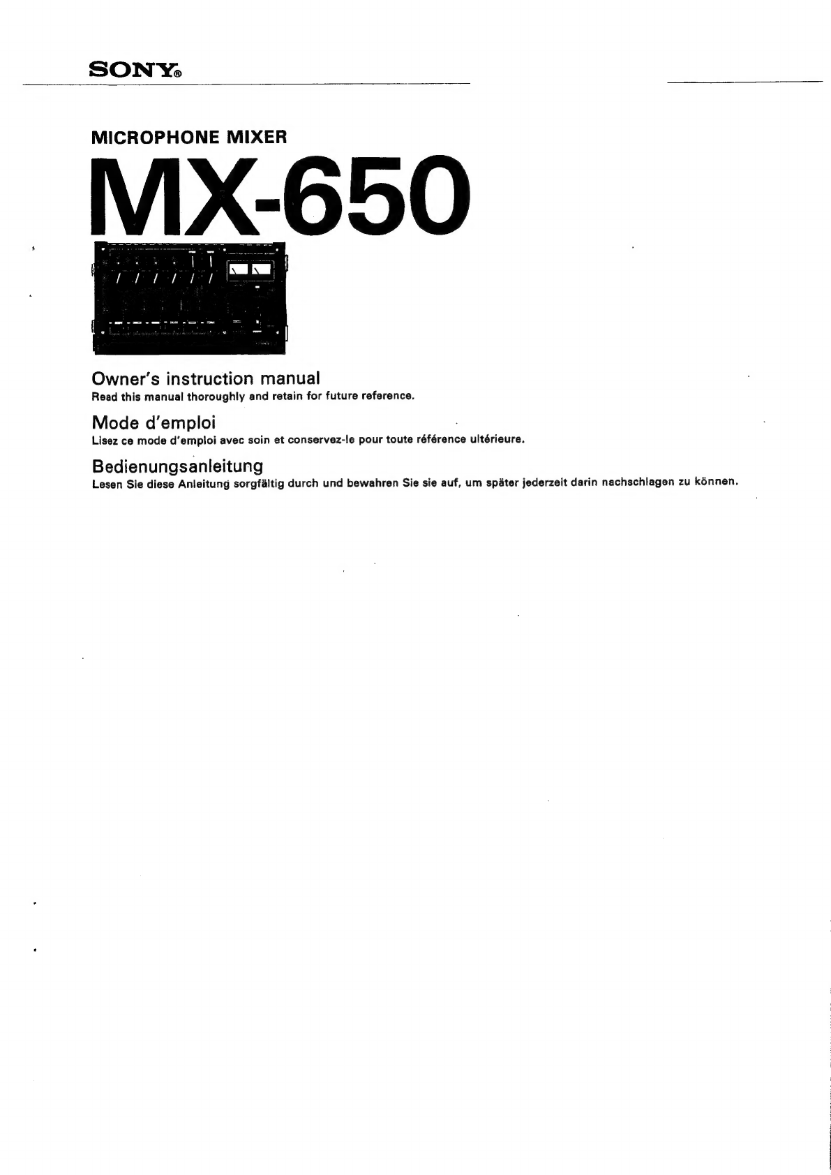
manuals.online logo
Brands
  1. Home
  2. •
  3. Brands
  4. •
  5. Sony
  6. •
  7. Music Mixer
  8. •
  9. Sony MX-650 Setup guide

Sony MX-650 Setup guide

Other Sony Music Mixer manuals

Sony XV-C700 User manual

Sony

Sony XV-C700 User manual

Sony SRP-X100 User manual

Sony

Sony SRP-X100 User manual

Sony mxp-29 User manual

Sony

Sony mxp-29 User manual

Sony Outdoor Storage User manual

Sony

Sony Outdoor Storage User manual

Sony SRP-V110 User manual

Sony

Sony SRP-V110 User manual

Sony DMXP01 User manual

Sony

Sony DMXP01 User manual

Sony Anycast station AWS-G500 User manual

Sony

Sony Anycast station AWS-G500 User manual

Sony MXP-290 User manual

Sony

Sony MXP-290 User manual

Sony FXE-120 User manual

Sony

Sony FXE-120 User manual

Sony SU-C3390 User manual

Sony

Sony SU-C3390 User manual

Sony MXP-S390 User manual

Sony

Sony MXP-S390 User manual

Sony MX-P21 User manual

Sony

Sony MX-P21 User manual

Sony MX-P21 User manual

Sony

Sony MX-P21 User manual

Sony SRP-X100 Installation and operation manual

Sony

Sony SRP-X100 Installation and operation manual

Sony SRP-X100 User manual

Sony

Sony SRP-X100 User manual

Sony RS-232C User manual

Sony

Sony RS-232C User manual

Sony MXP-310 User manual

Sony

Sony MXP-310 User manual

Sony SRP-X351P User manual

Sony

Sony SRP-X351P User manual

Sony DMXP01 User manual

Sony

Sony DMXP01 User manual

Sony OXFORD User manual

Sony

Sony OXFORD User manual

Sony PS4 CUH-1006A A Installation and operating manual

Sony

Sony PS4 CUH-1006A A Installation and operating manual

Sony PLAYSTATION VR User manual

Sony

Sony PLAYSTATION VR User manual

Sony SRP-X351P User manual

Sony

Sony SRP-X351P User manual

Sony SRP-X500P User manual

Sony

Sony SRP-X500P User manual

Popular Music Mixer manuals by other brands

Denon DN-HC5000 - Serato ITCH Hardware/Software... Service manual

Denon

Denon DN-HC5000 - Serato ITCH Hardware/Software... Service manual

Yamaha WC42260 owner's manual

Yamaha

Yamaha WC42260 owner's manual

Vertiv KMMLED156 Quick installation guide

Vertiv

Vertiv KMMLED156 Quick installation guide

Yamaha EMX3000 user manual

Yamaha

Yamaha EMX3000 user manual

Mackie Onyx Analogue Mixer brochure

Mackie

Mackie Onyx Analogue Mixer brochure

Peavey S-32 Sanctuary Series Operation guide

Peavey

Peavey S-32 Sanctuary Series Operation guide

Rane MP 4 Operator's manual

Rane

Rane MP 4 Operator's manual

True T9 Touchscreen Console owner's manual

True

True T9 Touchscreen Console owner's manual

Studiomaster Air Pro 24 instruction manual

Studiomaster

Studiomaster Air Pro 24 instruction manual

Yamaha MV802 owner's manual

Yamaha

Yamaha MV802 owner's manual

Roland SoundCanvas SC-8820 owner's manual

Roland

Roland SoundCanvas SC-8820 owner's manual

Roland M-160 owner's manual

Roland

Roland M-160 owner's manual

Yamaha MR1642 Operation manual

Yamaha

Yamaha MR1642 Operation manual

Pioneer DJM 909 - Battle Mixer W/Effects operating instructions

Pioneer

Pioneer DJM 909 - Battle Mixer W/Effects operating instructions

Veeder-Root TLS-350 Series System setup manual

Veeder-Root

Veeder-Root TLS-350 Series System setup manual

Alto APM80.QUAD user manual

Alto

Alto APM80.QUAD user manual

Omnitronic PM-211 user manual

Omnitronic

Omnitronic PM-211 user manual

SoundCraft B400 user guide

SoundCraft

SoundCraft B400 user guide

manuals.online logo
manuals.online logoBrands
  • About & Mission
  • Contact us
  • Privacy Policy
  • Terms and Conditions

Copyright 2025 Manuals.Online. All Rights Reserved.

SONY,
MICROPHONE
MIXER
Owner’s
instruction
manual
Read
this
manual
thoroughly
and
retain
for
future
reference.
Mode
d’emploi
Lisez
ce
mode
d'emploi
avec
soin
et
conservez-le
pour
toute
référence
ultérieure.
Bedienungsanleitung
Lesen
Sie
diese
Anleitung
sorgfaltig
durch
und
bewahren
Sie
sie
auf,
um
spater
jederzeit
darin
nachschlagen
zu
kénnen.
with
Parabolic
Reflector
Sony
PBR-400
Avec
le
Réflecteur
de
Son
Parabolique
Sony
PBR-400
mit
Parabol-Schalireflektor
Sony
PBR-400
een
Portable
tape
recorder
Location
Recording
Magnétophone
portatif
Enregistrement
extérieur
Tragbares
Tonbandgerét
Live-Aufnahme
We
Tape
deck
Magnétophone
Multi-mic
Recording
Tonbandgerét
Enregistrement
multi-microphonique
Aufnahmen
mit
mehreren
Mikrofonen
Sound
effect
tape
Bande
pour
un
effet
sonique
Tonband
fir
Klangeffekte
Background
music
Musique
de
base
Hintergrundmusik
Recording
of
Narration
Enregistrement
de
narration
Vokale
Aufnahmen
(Hoérspele,
Dokumentation)
Tape
deck
Magnétophone
Tonbandgerdt
=
Slim,
portable,
easy-to-operate...the
Sony
MX-650
is
an
ideal
electronic
microphone
mixer
which
incorporates
convenient
switch
circuitry
in
a
functional
layout.
The
MX-650
can
mix
up
to
6
channels
of
input
(3
stereo
pairs)
and
provide
2
channels
of
output
(stereo)
for
creative
mixing
results.
FEATURES
2-way
powering
system:
The
MX-650
operates
on
either
internal
batteries
or
AC
house
current
(with
the
Power
Adaptor
AC-12).
Output
channel
selector:
For
allowing
any
of
6
channels
of
input
to
be
switched
to
L
or
R
line
output.
In
addition,
each
output
channel
selector
can
be
set
to
feed
L
and
R
line
outputs
simulta-
neously.
Mic
attenuators:
For
reducing
excessive
mic
input
level
which
could
cause
mic
amplifier
distortion.
Pan-pot
control:
For
panning
the
sound
image
to
the
desired
por-
tion
between
L
and
R
channels.
LOW-
and
HIGH-level
line
outputs:
Suitable
for
matching
the
input
level
of
the
connected
audio
equipment.
Built-in
oscillator:
For
calibration
of
the
VU
meters
on
the
MX-650
and
the
connected
recorder
to
the
same
reference
level.
WARNING
@
To
avoid
electrical
shock,
do
not
open
the
cabinet.
Refer
servic-
ing
to
qualified
personnel
only.
@
To
prevent
fire
or
shock
hazard,
do
not
expose
the
set
to
rain
or
moisture.
TABLE
OF
CONTENTS
FUNCTION
AND
LOCATION
OF
PARTS
AND
CON'ROLG...........
6
OPERATING
PROCEDURE
SPECIFICATIONS
..............000000
see
BLOCK
DIAGRAM...........0cc::cceeseseesceeseeeeeeseeseeeeettne
Mélangeur
effilé,
portatif
et
d’une
utilisation
aisée...Le
Sony
MX-
650
est
un
mélangeur
idéal
de
microphone,
qui
assure
une
opéra-
tion
facile
avec
ses
touches
disposées
fonctionnellement.
Le
MX-650
peut
mélanger
au
maximum
6
canaux
d’entrée
(3
paires
de
stéréo)
et
pourvoit
de
2
canaux
de
sortie
(stéréo),
offrant
.
ainsi
un
effet
créatif
de
mixage.
’
PARTICULARITES
Deux
modes
d’alimentation:
Le
MX-650
fonctionne
sur
piles
intérieures
et
sur
le
courant
du
secteur
(avec
!’Adaptateur
d’Ali-
mentation
AC-12).
Sélecteurs
de
canaux
de
sortie:
N’importe
quel
canal
des
6
canaux
de
signaux
d’entrée,
peut
étre
passé
au
sortie
ligne
de
gauche
(L)
et
de
droite
(R).
De
plus,
chaque
sélecteur
de
canaux
de
sortie
peut
étre
mis
en
place
pour
alimenter
les
sorties
ligne
de
droite
et
de
gauche
simultanément.
Affaiblisseurs
de
microphone:
Pour
diminuer
le
trop
haut
niveau
d’entrée
de
microphone,
!equel
pourrait
causer
une
distorsion
de
V'amplificateur
de
microphone.
Réglages
de
potentiométre
panoramique:
Il
est
possible
de
dé-
placer
I’image
de
son
sur
|’endroit
désiré
entre
les
deux
canaux,
gauche
(L)
et
droit
(R).
Sorties
ligne
de
bas
niveau
[LOW]
et
de
haut
niveau
CHIGH]:
Ils
permettent
de
faire
correspondre
je
niveau
de
sortie
avec
le
niveau
d’entrée
des
appareils
connectés.
Oscillateur
incorporé:
||
permet
de
calibrer
les
VU-métres
du
MX-
650
et
du
magnétophone
connecté
au
méme
niveau
pour
réfé-
rence.
AVERTISSEMENT
@
Pour
éviter
toute
électrocution,
ne
pas
ouvrir
le
coffret.
Confier
lentretien
uniquement
a
un
personnel
quaiifié.
@
Pour
éviter
tout
danger
d’incendie
ou
d’électrocution,
ne
pas
exposer
l’appareil
a
la
pluie
ou
a
{’humidité.
“TABLE
DES
MATIERES
PARTICULARITES.
«.sccccecs
cvciciiassiebc
cts
ecectacenecensccewaseuceneceneaecess
AVERTISSEMENT.........::cccccceseeceeees
MODES
D’ALIMENTATION
FONCTION
ET
EMPLACEMENT
DES
COMMANDES
OPERATION?
scale
seavisesel
ses
bncctostetued
sugeceny
de
bdlsdesdascendecacchsetauaveas
SPECIFICATIONS
..............
SCHEMA
DE
PRINCIPE
Schmal,
tragbar
und
leicht
zu
handhaben,
ist
das
Sony
MX-650
ein
ideales,
elektronisches
Mikrofonmischpult,
das
sich
durch
praktische
Schaltméglichkeiten
und
funktionellen
Aufbau
aus-
zeichnet.
Durch
Mischung
von
bis
zu
6
Eingangskandlen
(3
Stereopaare)
auf
zwei
Ausgangskanale
(Stereo)
lassen
sich
mit
dem
MX-650
interessante
Mischergebnis
erzielen.
BESONDERE
MERKMALE
Zwei
Méglichkeiten
der
Spannungsversorgung:
Das
MX-650
kann
sowohl
mit
Batterien
als
auch
am
Netz
betrieben
werden
(mit
dem
Netzgerat
AC-12).
Ausgangswéahler:
Dadurch
kann
jeder
der
6
Eingangskandle
auf
den
linken
oder
den
rechten
Ausgangskana!
geschaltet
werden.
Dariiberhinaus
kann
jeder
Ausgangswéahler
so
geschaltet
werden,
daB
Sinker
und
rechter
Ausgang
gleicherma8en
gespeist
werden.
Mikrofon-Dampfungsschalter:
Dadurch
wird
zu
starker
Mikrofon-
eingangspege!
gedampft
und
Verzerrungen
des
Mikrofonverstar-
kers
vermieden.
Pan
Pot”-Regler
(Panorama
Potentiometer):
Mit
diesen
Potentio-
metern
kann
das
Klangbild
an
jede
beliebige
Stelle
zwischen
den
beiden
Ausgangskandlen
plaziert
werden.
Getrennte
Ausgange
fiir
hohen
und
niedrigen
Ausgangspegel:
Dadurch
wird
die
Anpassung
an
die
Eingaénge
der
angeschlossenen
Gerate
erleichtert.
Eingebauter
Oszillator:
Mit
dessen
Hilfe
kénnen
die
Aussteue-
rungsanzeigen
des
MX-650
und
des
angeschlossenen
Tonband-
gerates
auf
den
gleichen
Bezugspegel
geeicht
werden.
VORSICHT
@
Um
einen
elektrischen
Schlag
zu
vermeiden,
darf
das
Gehause
nicht
geéffnet
werden.
Wartungsarbeiten
sollten
nur
von
Fach-
leuten
vorgenommen
werden.
@
Um
einen
elektrischen
Schlag
oder
Brandgefahr
zu
vermeiden,
darf
das
Geraét
weder
Regen
noch
Feuchtigkeit
ausgesetzt
werden.
INHALTSVERZEICHNIS
BEDIENUNG.
....0
oo.
e
ec
ceeeeccceneeece
ea
nneeeeeeanaeeeeeeseeeaaseenee
ean
eeeetnneees
TECHNISCHE
DATEN....
BLOCKSCHALTPLAN
.............:.::ccses
3
Battery
compartment
Logement
des
piles
Batteriefach
Negative
polarity
Polarité
négative
Minuspol
~
(OSo0oSo5
+
Good
condition
Bon
état
des
piles
Guter
Zustand
HECK
Depress/Appuyer/Driicken
©©©
©
PLHOOH
©
HHH
GH
@O©OO®©®
DC
IN
12V
Power
adaptor
Adaptateur
d‘alimentation
Netzgerat
to
AC
outlet
a
une
prise
du
secteur
an
eine
Steckdose
POWER
SOURCES
BATTERIES
1.
Remove
the
battery
lid
as
illustrated
and
insert
the
batteries
(eight,
size
“C”
cells)
into
the
battery
compartment,
with
the
negative
polarity
(—)
of
the
battery
facing
toward
the
battery
lid
spring.
@
Refer
to
the
battery
polarity
indication
label
attached
on
the
bottom
of
the
MX-650.
2.
Replace
the
battery
lid.
Battery
life
When
the
battery
life
is
reduced
to
a
certain
degree,
the
tone
quality
of
the
mixing
sounds
will
be
degraded.
Before
starting
a
valuable
mixing
recording,
check
the
battery
condition
as
follows:
1.
Turn
on
the
POWER
switch.
2.
Depress
the
BATT
CHECK
button.
The
right
VU
Meter
will
indicate
the
battery
condition.
If
the
meter
does
not
remain
within
the
black
BATT
line,
replace
all
8
batteries.
Sony
super
size
“C”
batteries
(eight)
will
supply
approx.
45
hours
of
contiuous
operation
with
the
MX-650.
(Turn
off
the
POWER
switch
to
avoid
unnecessary
battery
con-
sumption
when
the
MX-650
is
not
to
be
used.)
@
When
the
mixer
is
not
to
be
used
for
a
long
period
of
time
or
is
operated
on
house
current,
remove
the
batteries
to
avoid
battery
leakage.
@
Use
fresh
batteries.
If
possible,
test
the
battery
condition
before
purchasing.
@
Keep
the
batteries
in
a
cool
place.
AC
HOUSE
CURRENT
Use
the
Sony
AC
Power
Adaptor
AC-12
(optional).
When
the
power
adaptor
is
connected,
battery
power
is
automati-
cally
disconnected.
For
detailed
operation
of
the
adaptor,
refer
to
its
instruction
manual.
@
Remove
the
batteries
to
avoid
battery
leakage
when
the
adaptor
is
to
be
used
for
a
long
time.
@
Disconnect
the
adaptor
when
the
MX-650
is
not
in
use.
Note
The
POWER
switch
will
be
automatically
turned
off
when
the
lid
is
closed,
even
with
the
POWER
switch
on.
MODES
D’ALIMENTATION
PILES
1.
Enlever
le
couvercle
de
logement
des
piles
comme
illustré.
Insérer
huit
piles
(format
“C”)
dans
le
logement
avec
la
polarité
négative
(~)
des
piles,
vers
la
rondelle
du
couvercle.
@
Se
référer
au
label
indiquant
la
polarité
des
piles,
fixé
au
fond
:
de
l'appareil.
2.
Refermer
le
couvercle.
Durée
des
piles
Lorsque
les
piles
sont
usées,
4
partir
d’un
certain
seuil,
la
qualité
tonale
sera
dégradée.
Avant
de
commencer
un
enregistrement
important
de
mixage,
vérifier
|’état
des
piles,
de
la
fagon
suivante:
1.
Mettre
!‘interrupteur
d’alimentation
[POWER]
sur
ON.
2.
Appuyer
sur
la
touche
de
vérification
de
|’état
des
piles
[BATT
CHECK].
Le
VU-métre
de
droite
indique
I’état
des
piles.
Si
!’ai-
guille
ne
reste
pas
sur
la
ligne
noire
indiquée
avec
BATT,
rem-
placer
toutes
les
huit
piles
par
des
neuves.
Les
huit
Piles
Super
Sony
format
“C”
permettent
environ
45
heures
d'utilisation
continue
du
MX-650.
(Lorsque
le
MX-650
n’‘est
pas
utilisé,
bien
mettre
l’interrupteur
d‘alimentation
[POWER]
sur
OFF
pour
éviter
une
usure
inutile
des
piles.)
@
Lorsque
l'appareil
n’est
pas
utilisé
pour
une
longue
période,
ou
est
alimenté
sur
le
secteur,
sortir
les
piles
afin
d’éviter
une
éven-
tuelle
fuite
d’électrolyte.
@
Utiliser
des
piles
neuves.
avant
de
les
acheter.
@
Conserver
les
piles
dans
un
endroit
tempéré.
Vérifier,
si
possible,
{’état
des
piles
COURANT
DU
SECTEUR
Utiliser
I’
Adaptateur
d’Alimentation
Sony
AC-12
(sur
option).
Lorsque
|’adaptateur
est
relié
a
|’appareil,
les
piles
intérieures
sont
automatiquement
déconnectées.
Pour
plus
de
détails,
se
référer
au
mode
d'emploi
de
l’adaptateur.
@Sortir
les
piles
afin
d’éviter
une
éventuelle
fuite
d’électrolyte
lorsque
|’adaptateur
est
utilisé
pour
une
longue
période.
@
Bien
débrancher
|’adaptateur
lorsque
l'appareil
n’est
pas
utilisé.
Remarque
L'interrupteur
d’alimentation
[POWER]
est
automatiquement
mis
sur
OFF
lorsque
le
couvercle
de
!’appareil
est
fermé,
méme
si
l'interrupteur
a
été
placé
sur
ON.
SPANNUNGSVERSORGUNG
BATTERIEN
1.
Nehmen
Sie
den
Batteriefachdeckel
ab
(s.
Abb.)
und
setzen
Sie
die
Babyzellen
(8
Stiick,
Norm
,,C“)
in
das
Batteriefach
ein,
so
da8
die
Minuspole
(-—-)
in
Richtung
des
Batteriefachdeckels
zeigen.
@
Die
richtige
Polung
der
Batterien
ist
aus
dem
Aufkleber
auf
der
Unterseite
des
MX-650
zu
ersehen.
2.
Bringen
Sie
den
Batteriefachdeckel
wieder
an.
Batterielebensdauer
Wenn
die
Batteriespannung
zu
weit
absinkt,
wird
die
Tonqualitat
der
gemischten
Programm
beeintrachtigt.
Ehe
Sie
eine
Aufnahme
von
Wert
beginnen,
priifen
Sie
den
Bat-
teriezustand
folgedermaS8en:
1.
Schalten
Sie
den
Hauptschalter
[POWER]
ein.
2..Driicken
Sie
auf
den
Batteriepriiftaste
[BATT
CHECK].
Der
Batteriezustand
wird
daraufhin
auf
dem
rechten
MeBinstrument
angezeigt.
Falls
die
Anzeige
nicht
in
dem
mit
,BATT”
bezeich-
neten
schwarzen
Bereich
bleibt,
sind
alle
8
Batterien
durch
neue
zu
ersetzen.
Bei
Verwendung
von
Sony
Super
Batterien
(8
Babyzellen)
ergeben
sich
ca.
45
Stunden
ununterbrochenen
Betrieb.
(Wenn
Sie
das
MX-650
nicht
in
Gebrauch
haben,
schalten
Sie
den
Hauptschalter
ab.
Sie
vermeiden
damit
unnétigen
Batteriever-
brauch.)
@
Wenn
Sie
das
Gerat
langere
Zeit
stillegen
oder
an
einem
Netz-
gerat
betreiben,
nehmen
Sie
Batterien
heraus,
um
deren
Auslaufen
zu
vermeiden.
@
Bevor
Sie
das
Gerat
in
Betrieb
setzen,
prifen
Sie
den
Batterie-
zustand
und
verwenden
Sie
wenn
mdglich
neue
Batterien.
@
Lageren
Sie
die
Batterien
kihl.
NETZANSCHLUSS
Verwenden
Sie
das
Sony
Netzgerat
AC-12
(auf
Wunsch
lieferbar).
Bei
AnschluB
des
Netzgerétes
werden
die
Batterien
automatisch
abgeschaltet.
Einzelheiten
iber
die
Bedienung
des
Netzgerates
entnehmen
Sie
bitte
dessen
Bedienungsanleitung.
@
Nehmen
Sie
die
Batterien
heraus,
wenn
Sie
das
MX-650
langere
Zeit
am
Netzgerat
betreiben;
Sie
vermeiden
dadurch
ein
Auslaufen
der
Batterien.
@
Wenn
Sie
das
MX-650
nicht
in
Gebrauch
haben,
entfernen
Sie
den
NetzgeratanschluB.
Hinweis
Wenn
der
Deckel
des
Mischpultes
geschlossen
wird,
schaltet
sich
die
Stromversorgung
automatisch
ab,
selbst
wenn
der
Haupt-
schalter
[POWER]
eingeschaitet
sein
sollte.
FUNCTION
AND
LOCATION
OF
PARTS
AND
CONTROLS
VU
meters
(dual
function
of
level
check
and
battery
check)
:
Pan-pot
controls
VU-métres
de
niveau
(fonctions
Réglages
de
potentiométre
doubles
de
I’indicateur
de.
niveau
et
panoramique
de
l'indicateur
de
!'état
des
piles)
Pan
Pot’’-Regler
Aussteuerungsanzeige
(gleichzeitig
Batteriezustandsanzeige)
‘
Output
channel
selectors
Sélecteurs
de
canaux
de
sortie
Meter
light
button
Ausgangswahler
Touche
d‘illumination
des
métres
Anzeigenbeleuchtungstaste
Battery
check
button
Touche
de
vérification
de
l'état
des
piles
Batteriepriiftaste
Input
selectors
Sélecteurs
d'entrée
Eingangswahler
Power
switch
Interrupteur
d‘alimentation
Hauptschalter
Preset
indicators
Index
de
repérage
Merkzerger
Headphone
output
Prise
de
casque
Kopfhoérerausgang
Input
gain
controls
Réglages
de
niveau
d’entrée
Eingangsregler
Master
control
Calibration
tone
switch
Réglage
de
niveau
maitre
Interrupteur
de
signal
de
calibration
Hauptpegelregler
Eichtonschalter
Output
channel
selectors
[OUTPUT
SELECT]
Feed
mic
or
line/phono
inputs
to
the
desired
channel
output.
Lieiiiecestty
Feeds
the
inputs
to
the
L
output.
Reiccpive
sce
Feeds
the
inputs
to
the
R
output.
BOTH......
Feeds
the
inputs
to
the
both
L
and
R
cutputs
simulta-
neously,
at
the
same
level.
This
facilitates
“center-mixing”
of
a
mono
source
such
as
announcements
or
solo
playing
between
channels.
Pan-pot
controls
(Panoramic
Potentiometer)
[PAIN
POT]
These
controls
allow
the
acoustical
positioning
of
the
correspond-
ing
input
signal
between
the
Left
and
Right
chanm!
output.
The
center
click
position
directs
the
signal
to
the
center
position
of
L
and
R
outputs.
This
position
is
equal
to
the
“BOTH”
position
of
the
OUTPUT
SELECT
switch.
.
FONCTION
ET
EMPLACEMENT
DES
COMMANDES
Line
outputs
(low
level)
Sorties
ligne
(de
bas
niveau)
Ausgange
(niedriger
Ausgangspegel)
Line
outputs
(high
level)
Sorties
ligne
(de
haut
niveau)
Ausgange
(hoher
Ausgangspegel)
External
power
input
Prise
d‘alimentation
extérieure:
NetzgerdtanschluB
Cascade
inputs
Prises
de
connexion
en
cascade
Kaskadeneingange
Sélecteurs
de
canaux
de
sortie
[OUTPUT
SELECT]
Choisir
la
position
correspondant
pour
alimenter
les
signaux
d’en-
trée
au
canal
désiré
de
sortie.
|
Ceres
Alimente
les
signaux
d’entrée
au
canal
gauche
(L)
de
sortie
Rigisisisses
Alimente
les
signaux
d’entrée
au
canal
droit
(R)
de
sortie
4
BOTH......
Alimente
les
signaux
d’enirée
aux
canaux
gauche
et
droit
simultanément
aux
niveaux
équivalents.
(Cette
position
facilite
le
“mixage
au
centre”
de
la
source
sonore
monophonique,
comme
une
narration
ou un
solo,
fait
entre
les
deux
canaux.)
Réglages
de
potentiométre
panoramique
[PAN
POT]
Ces
réglages
permettent
de
localiser
la
position
acoustique
des
signaux
d’entrée
entre
les
deux
canaux
de
sortie.
La
position
centrale
ot!
un
déclic
est
ressenti,
alimente
les
signaux
a
la
position
centrale
des
deux
canaux.
Cette
position
correspond
@
la
position
BOTH
des
sélecteurs
de
canaux
de
sortie
[OUTPUT
SELECT].
FUNKTION
UND
LAGE
DER
TEILE
UND
BEDIENUNGSELEMENTE
Ground
terminal
Borne
de
terre
Erdungsklemme
Mic
inputs
Prises
de
microphone
Mikrofoneingdnge
Line/phono
inputs
Prises
d'entrée
ligne/phono
Direkteingdnge
(Line/Phono)
Ausgangswahler
[OUTPUT
SELECT]
Damit
werden
die
entsprechenden
Mikrofon-
oder
Direkteingange
auf
den
gewiinschten
Ausgangskanal
geschaltet.
Leseiciastieees
Schaltet
die
Eingange
auf
den
L-Ausgang.
|;
oer
Schaltet
die
Eingaénge
auf
den
R-Ausgang.
BOTH......
Schaltet
die
Eingange
auf
beiden
Ausgangen
(L
und
R)
gleichzeitig,
mit
dem
gleichen
Ausgangspege!.
(Dadurch
wird
das
,zentrieren”
von
Mono-Quellen
wie
Ansagen
oder
Musiksolo
zwischen
den
beiden
Ausg&ngen
erleichtert.)
Pan
Pot”-Regler
(Panoramic
Potentiometer)
[PAN
POT]
Diese
Regler
sind
eine
Art
stufenlose
Ausgangswahler
und
ermég-
lichen
die
akkustische
Plazierung
des
betreffenden
Eingangssi-
gnals
an
jede
beliebige
Stelle
zwischen
den
beiden
Ausgangen.
Bei
eingerasteter
Mittelstellung
wird
das
Signal
gleichermaBen
dem
finken
und
rechten
Ausgangskanal
zugeteilt.
Diese
Stellung
der
Regler
entspricht
der
BOTH-Stellung
der
Ausgangswahler
[OUTPUT
SELECT].
my,
Microphone
~~
CONNECTION
DIAGRAM
SCHEMA
DE
CONNEXION
|
ANSCHLUSSPLAN
LINE
IN
Tape
recorder
Magnétophone
Tonbandgerat
Record
player
Tourne-disque
Plattenspieler
2
©©
DT
©®©
PZOQ
©
|OGHOOH®
i
es
ee
ee
OUTPUT
Tuner
Input
selectors
[INPUT
SELECT]
Select
the
inputs
connected
to
the
same
input
channel.
LINE
IN...Inputs
(such
as
tuner,
tape
recorder,
etc.)
connected
to
the
LINE
IN
jacks.
PHONO...Record
player
connected
to
the
PHONO
jacks.
Magnetic
phono
cartridges
are
recommended.
Crystal
types
are
not
recom-
mended
because
of
their
high
output
level.
Each
PHONO
input
incorporates
an
equalizer
circuitry.
MIC........
Mics
connected
to
the
MICROPHONE
jacks.
ATT........
This
position
is
useful
to
avoid
overload
distortion
of
mic
amplifier
when
recording
a
large
input
signal
on
location
(rock
music,
etc.)
or
recording
with
mic
too
close
to
the
source.
Use
this
position
when
the
meter
repeatedly
reads
over
O
VU
with
the
GAIN
CONTROL
set
around
the
“3”
position
or
below.
@
The
MX-650
uses
the
same
jack
for
line
and
phono
input
con-
nection.
The
internal
circuit
can
be
switched
by
setting
the
INPUT
SELECT
switch
to
either
the
LINE
IN
or
PHONO
position.
VU
meters
Indicate
line
output
level
selected
by
the
OUTPUT
SELECT
switch-
es.
The
“0
VU”
reading
indicates
the
rated
line
output.
The
right
meter
also
works
as
a
Battery
Check
Meter
with
the
BATT
CHECK
button
depressed.
Meter
light
button
[LIGHT]
To
read
the
meter
in
the
dark,
depress
this
button
for
a
few
sec-
onds,
and
the
meter
lights
briefly.
Battery
check
button
[BATT
CHECK]
To
check
battery
condition,
depress
this
button.
Power
switch
[POWER]
Turns
the
operating
power
on
or
off.
Calibration
tone
switch
[CAL
TONE]
To
match
the
VU
meters
of
the
MX-650
and
yourrecorder
to
the
same
reference
level,
the
MX-650
provides
calitration
signal
of
400
Hz
with
this
switch
set
to
ON.
The
rated
output
level
of
the
MX-650
is
obtained
when
adjusting
the
MASTER
control
for
0
VU
meter
reading.
For
the
calibration
procedure,
refer
to
page
12.
Note:
Do
not
set
this
switch
to
ON
while
recording,
or
the
input
signal
path
will
be
cut
off.
Headphone
output
[HEADPHONE]
Use
low
impedance
stereo
headphones
for
monitai
mg.
Sélecteurs
d’entrée
[INPUT
SELECT]
Choisir
1a
position
pour
les
signaux
d’entrée
branchés
sur
fa
prise
correspondante.
LINE
IN...Pour
les
signaux
d’entrée
branchés
sur
les
prises
d’en-
trée
ligne
CLINE
IN]
(tels
que
les
signaux
de
tuner,
de
magnéto-
phone,
etc.).
PHONO...Pour
un
tourne-disque
connecté
aux
prises
d’entrée
“phono
[PHONO].
Un
tourne-disque
équipé
d’une
cellule
magné-
tique
est
recommandé.
Un
tourne-disque
de
type
de
cristal
n’est
pas
recommandé,
a
cause
de
son
haut
niveau
de
sortie.
.
Les
prises
de
phono
sont
pourvus
des
circuits
de
correction.
MIC........
Pour
les
microphones
branchés
sur
les
prises
de
micro-
phone
[MICROPHONE].
ATT........
Cette
position
est
utile
pour
éviter
la
distorsion
causée
par
une
surcharge
de
!’amplificateur
de
microphone
lors
de
l’enre-
gistrement
des
gros
signaux
d’entrée
(musique
de
rock,
musique
moderne,
etc.)
ou
avec
un
microphone
placé
trop
prés
de
la
source
sonore.
Utiliser
cette
position
lorsque
!es
métres
dépassent
le
“O
VU"
plusieurs
fois,
avec
le
réglage
de
niveau
d’entrée
[GAIN
CONTROL
placé
sur
3
ou
inférieurs.
@Le
MX-650
utilise
les
mémes
prises
pour
les
connexions
des
entrées
ligne
et
des
entrées
phono.
Les
circuits
intérieurs
sont
adoptés
par
la
mise
des
sélecteurs
d’entrée
[INPUT
SELECT]
sur
la
position
correspondante.
VU-métres
de
niveau
Indiquent
le
niveau
de
sortie
de
chaque
canal.
La
déviation
sur
“O
VU”
indique
le
niveau
de
sortie
évalué.
Le
métre
de
droite
fait
aussi
office
de
l’indicateur
de
|’état
des
piles,
lorsque
la
touche
de
vérification
de
I’état
des
piles
(BATT
CHECK]
est
appuyée.
Touche
d’illumination
des
métres
[LIGHT]
Pour
observer
les
aiguilles
des
métres
dans
l’obscurité,
enfoncer
cette
touche
pour
quelques
secondes,
et
les
métres
sont
illuminés
un
bref
instant.
Touche
de
vérification
de
I’état
des
piles
(BATT
CHECK]
Pour
vérifier
|’état
des
piles,
appuyer
sur
cette
touche.
Interrupteur
d’alimentation
[CPOWER]
Mettre
l’appareil
sous
ou
hors
tension,
avec
cet
interrupteur.
Interrupteur
de
signal
de
calibration
[CAL
TONE]
Pour
calibrer
les
VU-matres
du
MX-650
et
du
magnétophone
con-
necté
au
méme
niveau
pour
référence,
un
oscillateur
incorporé
du
MX-650
produit
un
signal
de
calibration
de
400
Hz
avec
cet
interrupteur
placé
sur
ON.
Le
niveau
de
sortie
fixé
du
MX-650
sera
obtenu
lorsque
le
régiage
de
niveau
maitre
[MASTER]
est
ajusté
de
telle
facon
que
les
aiguilles
des
VU-métres
dévient
sur
“O
VU".
Pour
des
plus
amples
instructions
de
calibration,
voir
la
page
13.
Note:
Ne
pas
placer
cet
interrupteur
sur
ON
pendant
l’enregistre-
ment.
Sinon,
les
signaux
d’entrée
seront
interrompus.
Prise
de
casque
[HEADPHONE]
Pour
I’écoute
en
relais,
brancher
un
casque
stéréo
4
basse
impé-
dance.
Eingangswahler
[INPUT
SELECT]
Damit
werden
die
an
den
gleichen
Eingangskanal
angeschlossene
Eingange
geschaltet.
LINE
IN...Anschlisse
an
die
Direkteingangsbuchsen
[LINE
IN]
(z.
B.
Tuner,
Tonbandgerate:
usw.)
PHONO...An
die
Phonobuchsen
[PHONO]
angeschlossener
Plat-
tenspieler.
Plattenspieler
mit
magnetischem
Tonabnehmersystem
sind
am
besten
geeignet.
Kristalltonabnehmer
sind
nicht
zu
empfehlen,
da
sie
einen
sehr
hohen
Ausgangspegel
liefern.
Jeder
Phonoeingang
[PHONO]
ist
mit
einer
Entzerrerschaltung
gekop-
pelt.
MIC........
An
die
Mikrofonbuchsen
[MICROPHONE]
angeschlos-
sene
Mikrofone.
ATT........
Durch
diese
Schaltung
werden
Verzerrungen
durch
Ubersteuerung
des
Mikrofonverstarkers
bei
Eingangssignalen
mit
starken
Pegelspitzen
(z.B.
Rockmusik),
oder
wenn
sich
das
Mikro-
fon
zu
nahe
an
der
Schallquelle
befindet,
vermeiden.
Benutzen
Sie
diese
Schalterstellung,
wenn
die
Pegelanzeige
wiederhoit
iber
die
,,0
VU“-Marke
ausschlagt,
obwoh!
sich
der
Eingangsregler
[GAIN
CONTROL]
unterhalb
der
,,3“-Marke
befindet.
@
Das
MX-650
verwendet
fiir
Direkt-
und
Phono-Anschliisse
die-
selben
Eingangsbuchsen.
Die
Umschaltung
auf
die
entsprechende
Eingangsempfindlichkeit
erfolgt
durch
Stellung
des
Eingangswah-
lers
[INPUT
SELECT]
auf
LINE
IN
bzw.
PHONO.
Ausgangspegelanzeige
Dadurch
wird
der
durch
die
Ausgangswahler
[OUTPUT
SELECT]
bestimmte
Pege!
der
beiden
Ausgangskanale
angezeigt.
Die
,,0
VU“-Marke
entspricht
dabei
dem
Nennausgangspegel
des
jewei-
ligen
Kanals.
Wenn
man
die
Batteriepriiftaste
[BATT
CHECK]
driickt,
arbeitet
das
rechte
MeBgerat
als
Batteriezustandsanzeige.
Anzeigenbeleuchtungstaste
[LIGHT]
Um
die
Instrumente
auch
im
Dunkeln
ablesen
zu
kénnen,
driicken
Sie
diese
Taste
einige
Sekunden
und
dann
die
Anzeige
wird
wah-
rend
dieser
Zeit
beleuchtet.
Batteriepriiftaste
(BATT
CHECK]
Zur
Prifung
des
Batteriezustandes
driicken
Sie
diese
Taste.
Hauptschalter
[POWER]
Dadurch
wird
die
Spannungsversorgung
ein-
und
ausgeschaltet.
Eichtonschalter
[CAL
TONE}
Um
die
Pegelanzeigen
des
MX-650
und
des
aufnehmenden
Ton-
bandgerates
auf
den
gleichen
Bezugspege!
abzustimmen,
liefert
das
MX-650
bei
eingeschaltetem
Oszillator
(Eichtonschalter
,,ON”)
einen
400
Hz
Eichton.
Den
Nennausgangspegel
des
MX-650
erhalten
Sie,
indem
Sie
mit
dem
Hauptpegelregler
[MASTER]
die
Pegelanzeigen
auf
,,0
VU”
einstellen.
(s.
,,Eichung
der
Pegelan-
zeige”
S.
13)
Hinweis:
Schalten
Sie
diesen
Schalter
auf
keinen
Fall
wahrend
der
Aufnahme
ein,
da
hierdurch
die
Eingange
abgetrennt
werden.
Kopfhérerausgang
[HEADPHONE]
Benutzen
Sie
zum
Mithdéren
der
Aufnahme
einen
Stereo-Kopfhérer
von
niedriger
Impedanz.
10
—
KASKADENSCHALTUNG
VON
ZWEI
MX-650
CASCADE
CONNECTIONS
OF
TWO
MX-650
CONNEXION.
EN
CASCADE
DE
DEUX,
MX-650
Signal
flow
of
the
Master’s
mixing
Le
cours
des
signaux
mélangés
avec
le
mélangeur
maitre
Ses
Sonata
der
Hauptstufe
<—
Signal
flow
of
the
slave’s
mixing
Le
cours
des
signaux
mélangés
avec
fe
mélangeur
filial
Signalflu8
der
Unterstufe
Master
mixer
Mélangeur
maitre
Hauptstufen
Mischpult
SS
@©@®
DW
PHP
OLOHHEGLHHHHOOOO®
Slave
mixer
Mélangeur
filial
Unterstufer
Mischpult
CASCADE
IN
it
\sereeveeeennnsenseeerineemeetsienaanpensteteersmnnemttietersretuemsetesiesnatrensnuimunanettmaernettemanseensnenamaee
Master
control
[MASTER]
Once
the
various
sources
are
properly
mixed
with
each
input
GAIN
CONTROL,
adjust
the
overall
output
level
with
this
control.
The
L
and
R
output
levels
are
adjusted
simultaneously.
This
facilitates
fade-in
and
fade-out
effects.
Preset
indicators
Use
as
a
reference
point
when
temporary
level
changes
are
necessary.
Input
gain
control
[GAIN
CONTROL]
Adjusts
either
the
mic
or
line/phono
input
level.
Each
contro!
number
corresponds
to
those
of
input
(mic
or
line/
phono)
channel.
For
example,
to
adjust
input
channel
[i]
level,
use
the
control
[f4].
Watch
the
meters
as
a
guide.
Slide
all
GAIN
CONTROLs
not
in
use
to
“O”
position
in
order
to
achieve
the
best
S/N
ratio
possible.
Generally
setting
between
5
and
8
is
recommended
for
better
S/N,
and
low
distortion
results.
Earth
terminal
[
ny
)
When
a
record
player
or
other
connected
audio
equipment
requires
earth
connection
to
reduce
hum
or
other
offensive
noise,
use
this
terminal.
MIC
inputs
(phone
type)
[MICROPHONE]
Accept
low
impedance
mics.
Line/phono
inputs
(phono
type)
[LINE
IN/PHONO])
Accept
outputs
of
a
tape
recorder,
tuner,
amplifier
or
record
player.
Cascade
inputs
(phono
type)
[CASCADE
IN]
For
cascade
connection,
connect
a
second
or
third
MX-650
to
these
inputs.
External
power
inputs
[DC
IN
12
V]
Connect
the
Sony
Power
Adaptor
AC-12
to
this
input.
Line
outputs
(LINE
OUT]
Feed
MX-650
line
outputs
to
tape
recorder
or
amplifier
inputs.
Select
either
the
HIGH-
or
LOW-level
outputs
matched
to
the
con-
nected
audio
equipment.
HIGH
(phono
type)......Suitable
for
line
inputs
of
tape
recorder
or
stereo
amplifier.
LOW
(phone
type)......
Suitable
for
mic
input
of
tape
recorder
or
vocal
amplifier.