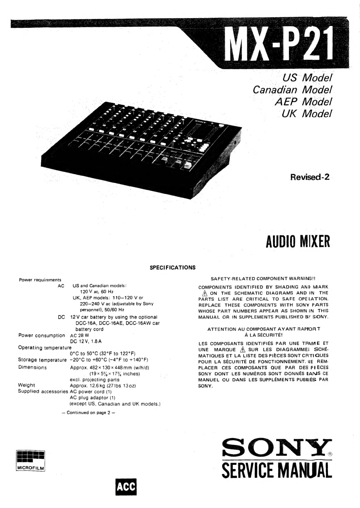
Sony MX-P21 User manual
Other Sony Music Mixer manuals

Sony
Sony SRP-V110 User manual

Sony
Sony PS4 CUH-1006A A Installation and operating manual

Sony
Sony MX-P21 User manual

Sony
Sony MX-650 Setup guide

Sony
Sony SRP-V200 User manual

Sony
Sony OXF-R3 User manual

Sony
Sony SRP-X700P User manual

Sony
Sony Anycast station AWS-G500 User manual

Sony
Sony SRP-X351P User manual

Sony
Sony DMXP01 User manual