LA-EA4
2-5
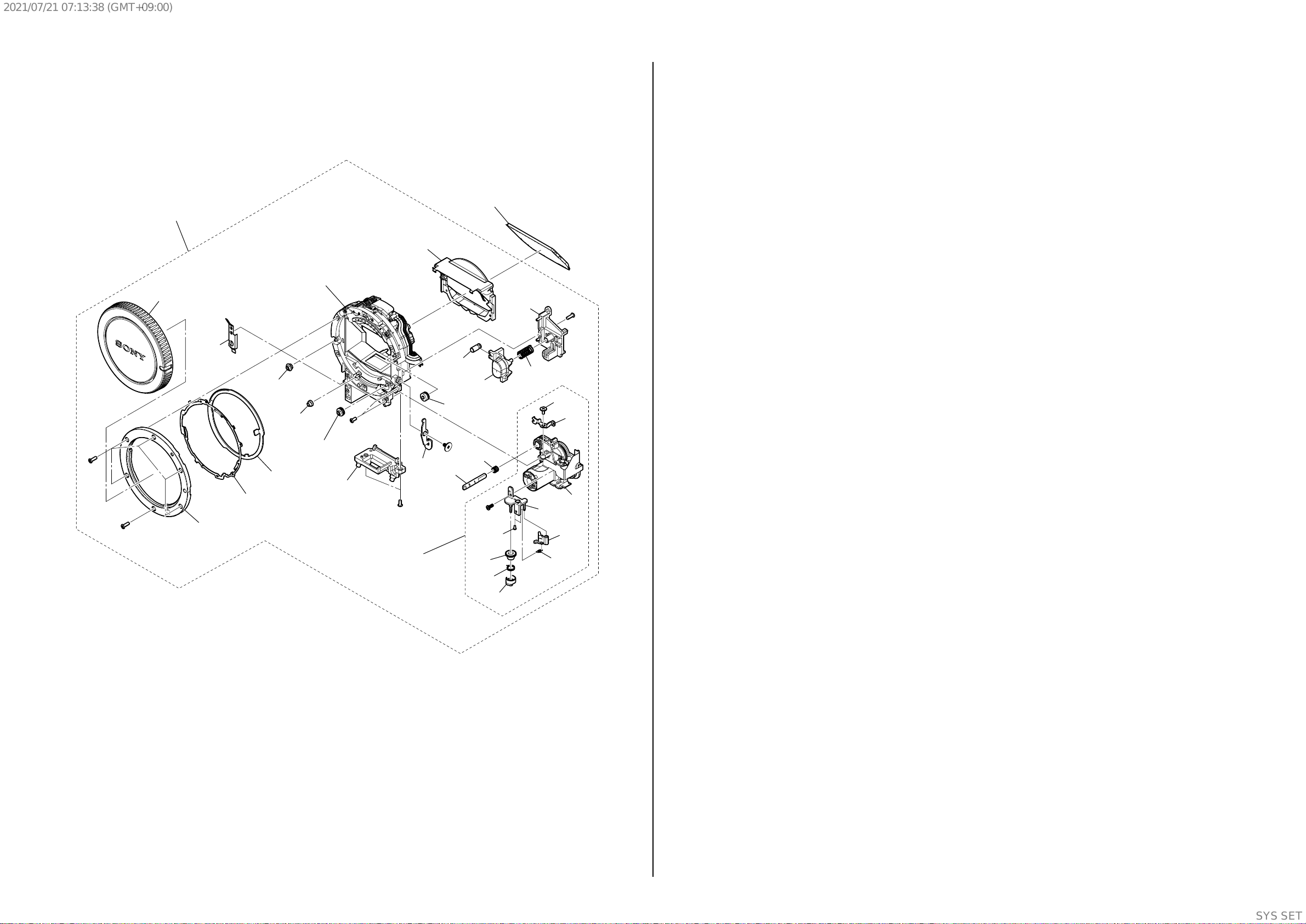
2-1-3. MIRROR BOX SECTION
ns: not supplied
Ref. No. Part No. Description Ref. No. Part No. Description
101 A-1973-484-A MB M-BOX SHIPPING ASSY (Note 1)
102 4-292-532-11 MB A MOUNT (Note 2)
103 4-292-534-02 MB RING SP COM
104 4-141-107-12 MB BODY CAP
105 2-689-314-01 ROLLER (B), RING (Note 3)
106 3-277-916-01 ROLLER (C), RING (Note 3)
107 3-283-668-01 ROLLER A (SV), RING (Note 3)
108 4-464-681-01 AP RING ROLLER D (Note 3)
109 4-296-502-01 MB AFM PLATE
*110 4-141-092-01 MB LENS LOCK PIN
111 4-296-494-01 MB LENS LOCK BUTTON SP
112 4-141-108-01 AF COUPLER
*113 4-141-103-01 AF COUPLER TENSION SP
114 A-1844-420-A AF DRIVING UNIT (Note 1)
*115 2-689-289-11 SHAFT, COUPLER LEVER
116 4-292-469-01 AF DMF DECELERATION GEAR
117 4-292-472-01 AF DMF CLUTCH SP
118 4-292-470-01 AF DMF CLUTCH CAM
119 4-292-465-01 AF DMF CLUTCH LEVER
120 4-292-471-01 AF DMF CLUTCH LEVER TENSION SP
121 A-1976-037-A P.O.I (3G) SERVICE (Note 4, 5)
#23 3-080-204-11 SCREW, TAPPING, P2
#76 2-666-551-11 SCREW, TAPPING, P2
#163 2-695-575-11 SCREW (T2), +P1 PAN TAPPING
#165 2-695-434-31 SCREW (T1.7), HEAD PAN TAPPING
DISASSEMBLY
Screw
#23: M1.7 X 4.0 (Tapping)
(Black)
3-080-204-11
4.0
1.7
#76: M1.7 X 4.0 (Tapping)
(Silver)
2-666-551-11
4.0
1.7
5.5
2.0
#163: M2.0 X 5.5 (Tapping)
(Silver)
2-695-575-11
3.0
1.7
#165: M1.7 X 3.0 (Tapping)
(Silver)
2-695-434-31
#76
#163
103
102 (Note 2)
108 (Note 3)
111
119
115
110
121 (Note 4, 5)
120
118
117
116
112
113
114
109
107
(Note 3)
106
(Note 3)
105
(Note 3)
101 (Note 1)
ns
ns
ns
ns
ns
ns
ns
(including AF motor and
AFP-008 flexible
complete board) (Note 1)
ns
ns
ns
ns (including AP aperture unit)
(Note 5)
ns (Note 3)
#165
#23
#23
#23
104 AP Iris Ring
Pin
Stop position
(iris-in end)
Pin
Hole of the front frame
Cutout of the sensor gear
P Iris Ring Removal
Rotate the AP Iris Ring clockwise, and remove it at the stop position (iris-in end).
After fixing the sensor gear by inserting the pin (approx. 1 mm in diameter) through the hole of front frame and dropping
the tip of pin in the cutout of sensor gear, remove the AP Iris Ring.
Note 1: When replacing this part, carry out adjustment. Refer to
“1-5. NOTE ON PART REPLACEMENT” for details.
Note 2: Refer to “Assembly-6: Notes on assembling the MB A
Mount” when assembling.
Note 1: この部品を交換した場合は調整が必要です。詳しくは“1-5.
部品交換時の注意”を参照してください。
Note 2: 組立時は“Assembly-6: Notes on assembling the MB A
Mount”を参照してください。
Note
Note 3: Refer to “Assembly-7: Notes on assembling the AP Iris Ring
and ring rollers” when assembling.
Note 3: 組立時は“Assembly-7: Notes on assembling the AP Iris
Ring and ring rollers”を参照してください。
Note 4: Refer to “1-6. NOTES ON REPLACING THE P.O.I. (3G)
SERVICE” when assembling.
Note 4: 組立時は“1-6. P.O.I. (3G) サービス交換時の注意”を参照して
くだ さ い 。
Hold the P.O.I at the both sides.
Insert the P.O.I. (3G) to the MB Mirror Frame and attach it to the hooks as shown by arrows.
Note 5: Notes on assembling the P.O.I. (3G)
Be careful not to drop the P.O.I. (3G) from the MB Mirror Frame when assembling the P.O.I. (3G) to the MB M-Box Shipping Assy.
Hold here.
NOTES ON HOLDING THE P.O.I. (3G)
SYSSET
2021/07/2107:13:38(GMT+09:00)