TitleSection
-- Page
SERVICE NOTE
Parts Location Diagram Related to Power Supply...............
6
Semiconductor Location................................................
6
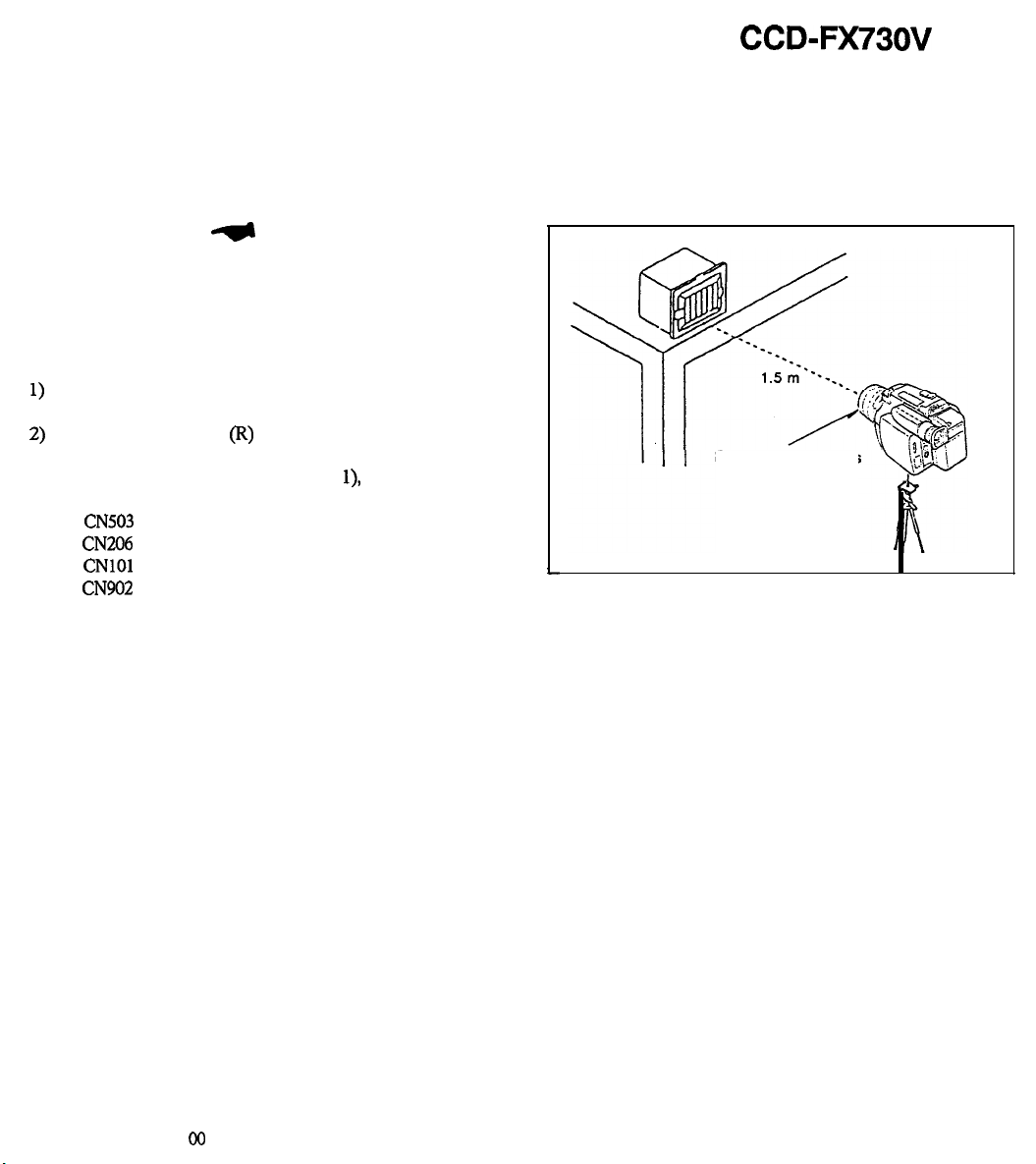
Head
Cleaning..
..........................................................
6
1. GENERAL
Notes and
pr-utions..
................................................
1-1
Checking
Supplied
Accessories
......................................
1-1
Charging and Installing the Battery Pack........................... l-2
lns&ingaC~s&e..
...................................................
1-3
Camera
R-ding..
.....................................................
1-4
Hin~forBe~erShooting ...............................................
1-6
Checking
the
Rem&d
picture
......................................
1-6
Playing
Ba&aTape..
..................................................
1-7
Using
Altemative
PowerSources
....................................
1-8
RecordingwiththeDateorTime .....................................
1-8
RecordingwiththeAge .................................................
1-g
Shootingwith Backlighting..
...........................................
1-10
“sing
the
PROGRAM
AE
Function
..................................
1-10
Fade-in
and
Fade-out
..................................................
1-11
ChangingtheModeSettings.. ........................................
1-11
Connations
for
Playback..
............................................
1
_I
2
Editing onto Another Tape ............................................
,_,3
R-~ingfroma~orVCR..
........................................
1-13
Changing
the
Lithium
Battery..
.......................................
1-14
Resetting
the
Date
or
Time
............................................
1-14
,,,aybck
Modes..
........................................................
,
_,
5
TipsforUsingtheBattery
Pack
.......................................
1-15
Maintenance information and Precautions ........................
,_,5
Using
Your
&mm&r
Abroad..
.....................................
1
_I
8
identifying
the
P&s
.....................................................
1
_I
g
lndic-atom
intheViewfin&r
............................................
j-22
2. DISASSEMBLY
2-5-l. Removal of Cabinet (R) Assembly ..........................
2-1
2-S-2. Removal of Control Switch Block (CK) ..................... 2-l
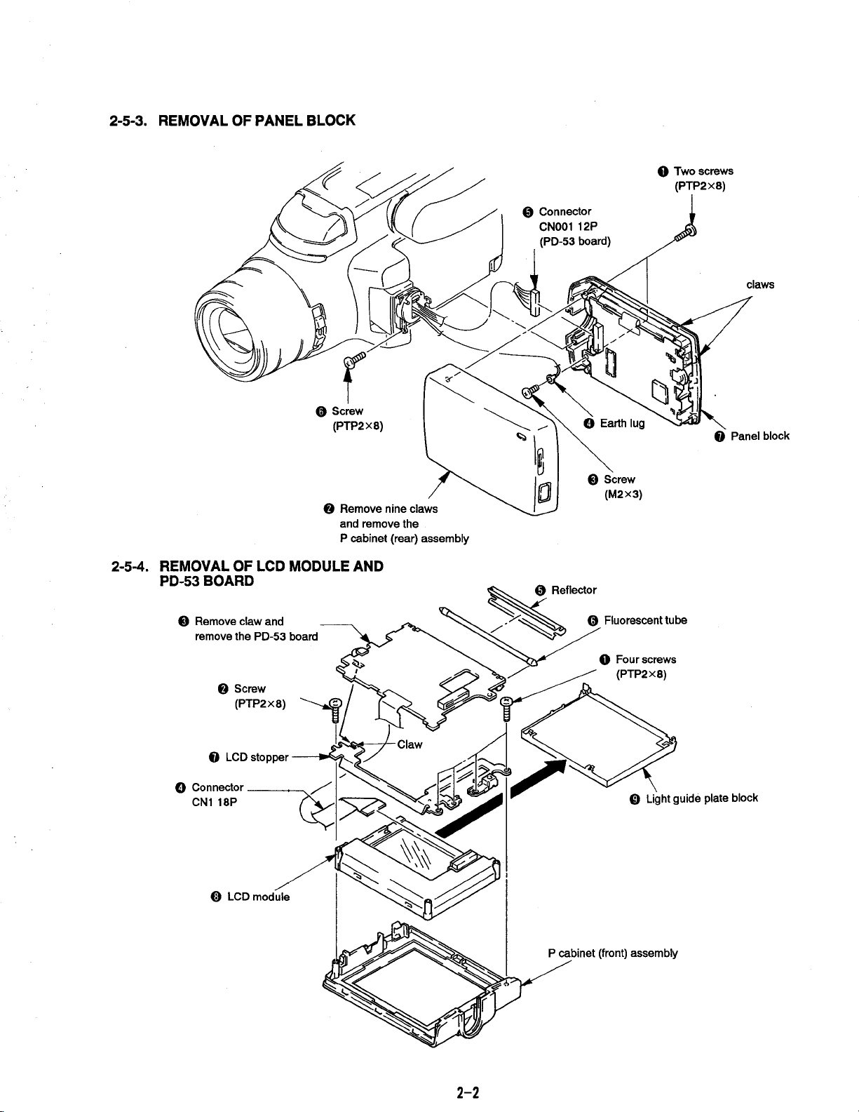
2-5-3. Removal of Panel Block.. ..................................... 2-2
2.54. Removal of LCD Module and PD-53 Board............... 2-2
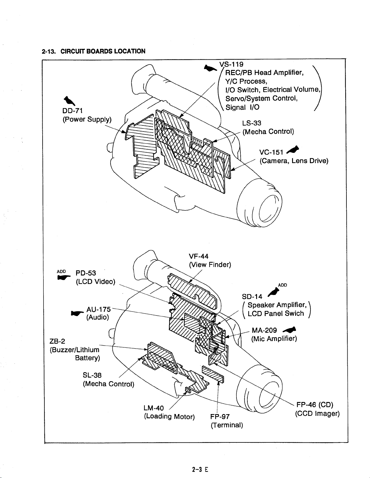
2-13. Circuit Boards Location ........................................ 2-3
Section
Title
3.
BLOCK DIAGRAMS
3-l. Overall
BlockDiagram..
.......................................
3-l
3-2.
Video (1) Block Diagram ...................................... 3-5
3-3.
System Control Block Diagram .............................. 3-g
3-4.
Audio Block
Diagram..
......................................... 3-14
3-5.
LCD Block
Diagram..
........................................... 3-17
3-6.
Power Block Diagram ..........................................
3-21
4.
PRINTED WIRING BOARDS
AND SCHEMATIC DIAGRAMS
4-l.
4-2.
Frame Schematic Diagram ...................................
4-1
Printed Wiring Boards and Schematic Diagrams ........ 4-4
l VC-151 (Camera, Lens Drive) Board ................... 4-5
.
VC_151
(Camera
(1))
Board..
............................ 4-7
.
VC_151
(Camera (2)) Board.. ............................ 4-10
.
VC_,5,
(L
ens
Drive) Board.. ............................. 4-13
l VS-11
g
(REC/PB
Head Amplifier, Y/C Process,
l/O
Switch, Electric Volume, Servo/System Control,
Signal
I/O).....................................................
4-t
7
l VS-llg
(REC/PB
Head Amplifier) Board ..............
4-21
.
VS_ttg
(v/C process) Board............................. 4-24
l VS-11
g
(l/O
Switch, Electric Volume) Board ......... 4-27
l VS-11
g
(Servo/System Control) Board ................ 4-30
.
VS_1
1
g
(Signal
l/O)
Board
................................ 4-33
l
SD-14 (Speaker Amp, LCD Panel Switch) Board ... 4-35
.
PD_53
(LCD Video) Board ................................
445
.
DD_71
(Power Supply) Board ............................ 4-53
5.
5-l.
REPAIR PARTS LIST
Explod~View~
. . . . . . . . . . . . . . . .
............
. . . . . . .
..........
. . . .
5-1
Page
5-1-1.
Front Case Block
Assembly..
............................
5-1
5-l-2,
Cabinet(L) BlockAssembly .............................. 5-2
5-t-3.
Cabinet(R) BlockAssembly............................. 5-3
5-l -4.
EVF
Block
Assembly..
..................................... 54
5-l -5.
Main
Boards
Assembly..
.................................. 5-5
5-1-5. CCD
Block
Assembly..
....................................
5-S
5-l -7. Zoom Lens Assemblies (LSV-140A)
(VCL5412WA)
(VCL_5412WB).
........................ 5-7
5-1-12,
Panel Block Assembly.. ...................................
5-S
5-2,
Efe&imf
Parts
List..
........................................... 5-g
HARDWARE
LIST.. ..................................................... 5-24
-4-