BEle)(-me)
mOxe)
alc=lalts
Chapter
1
Overview
Chapter
2
Location
and
Function
of
Parts
Chapter
3
Preparations
Chapter
4
Menu
Flowchart
_
(Using
the
RM-D800
.Remote
Control
Unit)
Chapter
5
Operation
(Continued)
3-2
4-1
4-2
4-4
4-5
4-6
5-1
5-2
5-7
5-8
5-9
Features
.....csccsscsscccescccecssscsenscsssccsscrsccaccssssecseessossoncsenssvccsooses
1-2
Use
of
Capital
Letters
in
This
Manual................cccsssssesesees
1-4
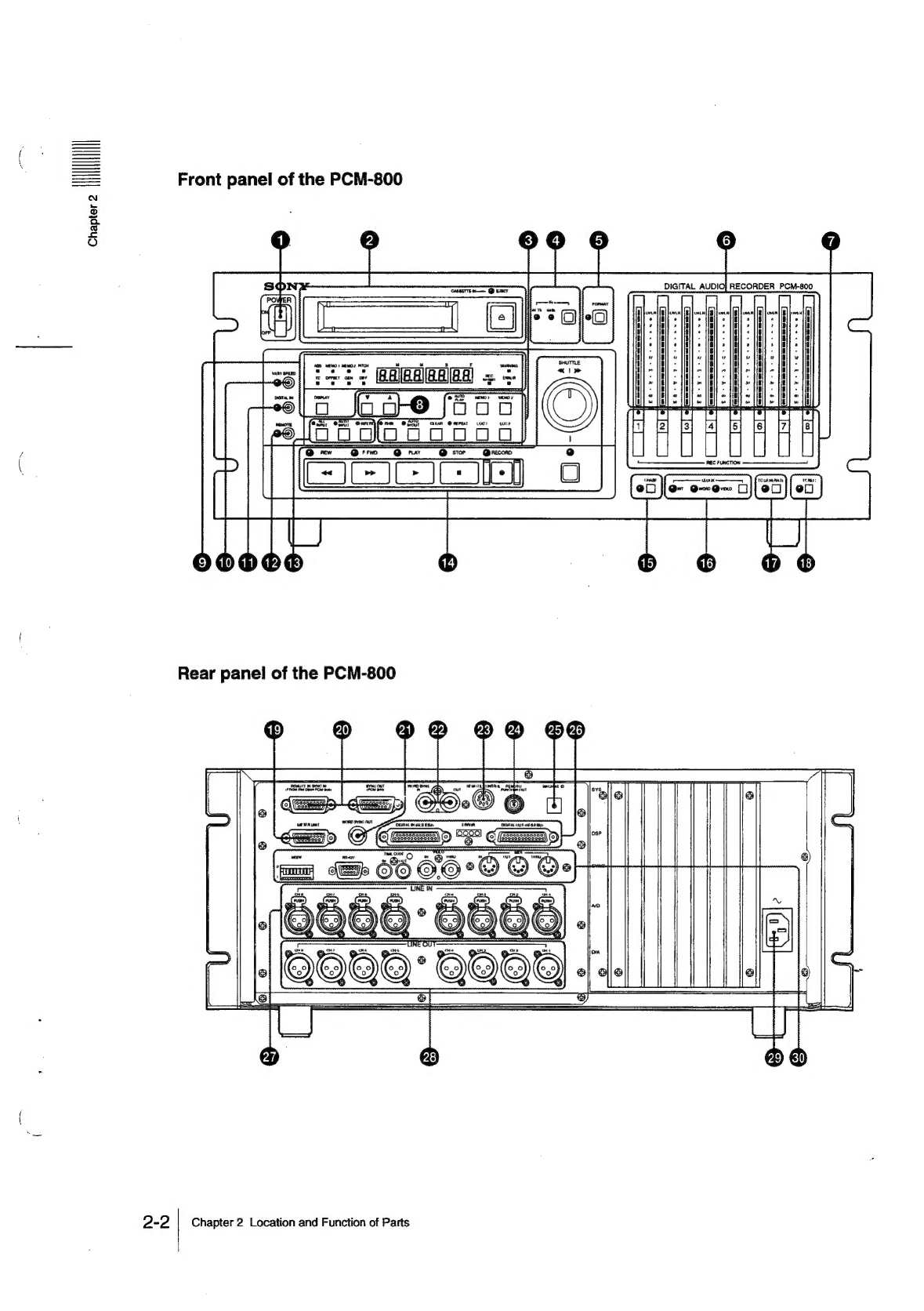
Front
Panel
of
the
PCM-800
.............sccsosscsssssssscssscrenssncreesees
2-2
Rear
Panel
of
the
PCM-800
...............sccssossesssscrssscsesssseoncenes
2-7
Front
Panel
of
the
RM-D800
..................ccsscssssssscsesccenessenees
2-12
Rear
Panel
of
the
RM-D800
...............ccsssssssssscssesseossecseosees
2-17
Precautions
.........ccccsccccscccsccccesscscecscscsecsecsenscessncssessoscsensooccsoes
3-2
CONMOCTON
aeap
ssscesdecsssccas
ccna
tcorasezesaarateiccin
ssa
setepoes
sesomoesaane
3-4
System
Configuration
...........cceccsscescesececectseterseesceeeueesereeeaeses
3-4
When
the
DABK-801
Interface
Board
is
Installed
..................
3-5
Overview
of
the
Menu
Flowchart
........sesrsssessssensessesssssecees
4-2
Menus
for
Setting
the
Items
of
GROUPs
1
and
2...............
4-4
4-2-1
GROUP
1
Ment
.....::c.is0sechasacenciewasina
4-4
4-2-2.
"GROUP
2
Men
isiecietincasiecicietieh
nie
tercrtaeduinacs
4-5
Menus
for
Setting
the
Items
of
GROUPs
3
and
4...............
4-6
4-3-1
GROUP
3
Men
ou...
cece
eeceeeceeseeeenereneesseeeseeneeees
4-7
4-3-2
GROUP
4
Menu
ou...
cee
eeccesccescsceeseeesseesasceatecseeessenees
4-8
Instant
Access
to
the
Memnus..........s.scssccscsssessssscecesssescsssessonees
4-9
Menu
for
Resetting
the
Function
.............s.ssssscsssssscecsssseess
4-10
Menu
for
Selecting
the
Machine................scossssssssssrssssessoes
4-11
4-6-1
Setting
the
RS-422
Control
Mode
..........
ee
eeeeeeeeeeees
4-12
Formatting
a
Tape.
.........cccccscsscsscesessescenes
sadedscaeasscéeasssesesssesese
5-2
Audio
Recording
..........secscssssescecccessssescccerssesssscrcessscssescecsees
5-4
Tpitial
RECORDS
2uc5cssenteerscccrviveseisnesl
cestoencrsnoernnatineuuse
5-4
Punch-in
(Insert)
Recording
..........cscsesecseseseeseeeceseeeneeeseeeeees
5-5
Copy
Between
Channels
(Track
Bouncing)
.........ccccsseseeeee
5-10
Entering
a
Track
Delay
Time...
cece
cssssetseereeseesseseeecne
5-11
Variable
Speed
Playback.
.............cscssssscossresseesseceseseonseese
5-12
Autolocation
Controls
...............scccccssscsscsseseccesssscsscssesseessoese
5-13
Multiple-PCM-800
System
(Without
the
DABK-801)......
5-15
SyMchron
Zations
scctatescvedestralsraleaisateatagcueaiasewohadans
5-15
Striping
Time
Code
(With
the
DABK-801)
.........ssssssssesee
5-19
PECUNIARY
ss
2c
cadaid
en
con
aevvcavadadsannteadenkatenraenstpubamibecsctalasenbscnteons
5-19
Recording
Time
Code
on
the
PCM-800
00...
cece
ceeeeeeeeeee
5-20
Recording
Time
Code
on
Other
Audio
Tape
Recorders
........
5-25
Dubbing
Audio
and
Time
Code
between
PCM-800s
at:
Orie
Time
356.
foc
2s
seca
cadhoseetédedats
Siacvasdoesttiedssasacsccaesseness
5-27
Syncing
with
the
PCM-800
as
Slave
(with
the
DABK-801)
...........ccscsssssosrsscssevesverecceersecsseees
5-30
Procedure
for
Synchronization...
seeeseesceeeeeeeseeeeeeeeeeees
5-30
SYNC
OfFSCt
cos.
cesh
ss
be
ceeces
ded
desiveat-decesenc
guise
esses
datvasstestoveate
nes
5-32
Time
Code
Out
Select
............scccssscsscsssscsccsescessscessesees
aibesiacs
5-35
Bs
SHG
Select
ccc
iccctcosescceccstaabciacannisinsssicaiasstivasssechoneerpaceetses
5-37
Table
of
Contents
1
(ININIIH