Overview 3
Overview
Features
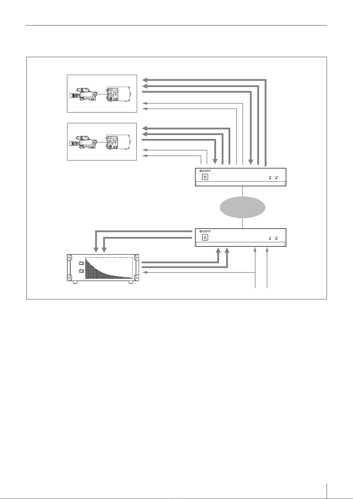
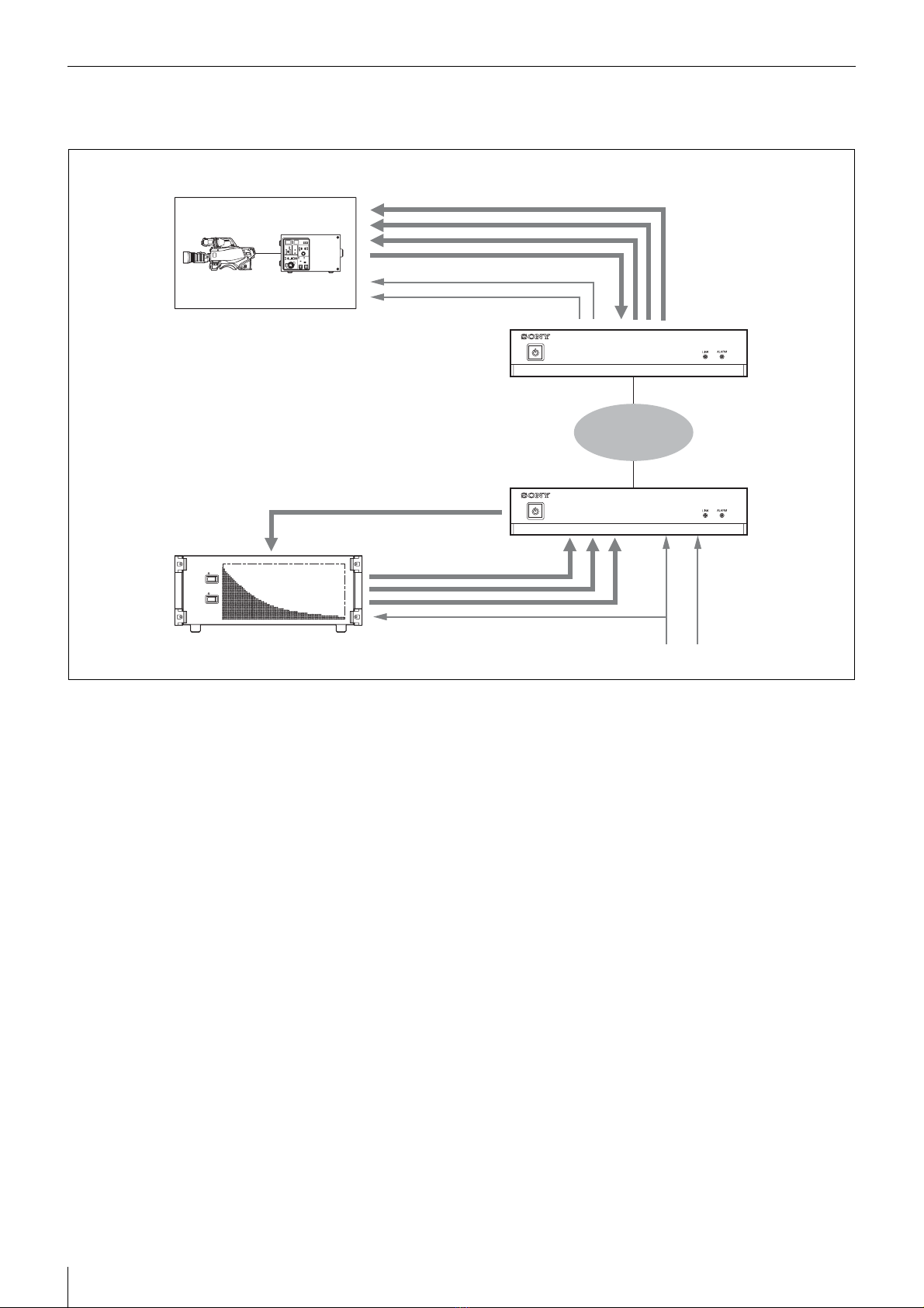
The NXL-IP55 IP Live Production Unit is an IP
transmission device that allows upstream and
downstream transmission of HD video signals, audio
signals, and various control signals with low latency of
less than one field (excluding network delays). Using the
unit allows you to configure a live production system over
a network.
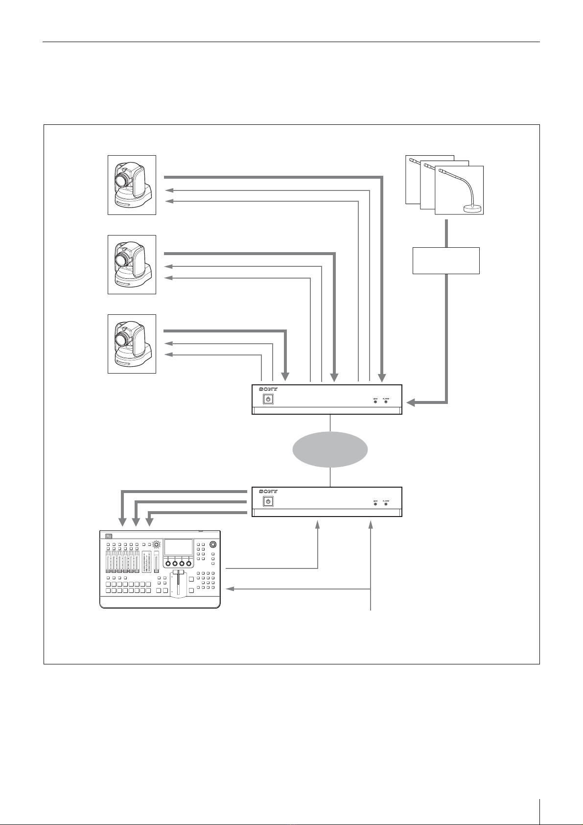
Network synchronization
Devices can be synchronized via a network. Low-latency
video transmission is made possible during live
production by eliminating the need for synchronization
via a frame synchronizer.
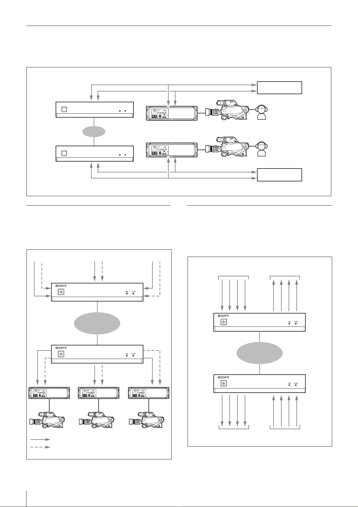
Various transmission signals
Up to four video channels are available for transmission
with up to three in the same direction. Ten audio channels
(five pairs) are available for transmission with eight in the
same direction. Eight GPIO channels, six tally channels,
and one channel for a synchronization signal are also
available.
The content of this document applies to firmware version
V1.10.
NXL-IP55 units with different firmware version cannot
be connected together. You can check the firmware
version in [Device Information] on the [Status] page in
the Web menu.
If using an NXL-IP55 unit with a different firmware
version, contact your store or point of purchase.
Transmittable Signals
Video signals
1080/50i, 1080/59.94i, 720/50P, 720/59.94P,
1080/25PsF, 1080/29.97PsF
Can transfer up to four channels of HD SDI signals,
with up to three in the same direction.
1080/50P, 1080/59.94P
Can transfer total of two channels using Dual Link
SDI, with one in each direction.
Signals with different formats cannot be transferred at the
same time.
Audio signals
Up to five pairs of two channels (48 kHz/24 bit) are
available for audio signals, analog audio signals, and
intercom signals embedded on HD-SDI signals (up to
eight channels in the same direction).
• HD-SDI embedded audio can be transmitted on Ch1 to
Ch2 or Ch1 to Ch4. The audio will not be transmitted
on Ch5 and above.
Metadata attached to HD-SDI signals cannot be
transmitted.
• When transferring Dual Link SDI, audio signals can be
embedded in Link-A only.
Tally signals
Three channels each are available for R tally signals and
G tally signals.
However, the transmission direction for all channels is the
same.
GPIO
Eight channels are available.
The transmission direction can be switched by using four
channels as one group.
Supported Networks
Use this unit in a network that meets the following
specifications. Check whether the network you want to
use fulfills these requirements by performing a network
test in the web menu before use.
The network test only displays the status of the area that
can be detected at the moment the test is executed. It does
not guarantee the quality of the network or the operation
of this unit.
Network connected to the MAIN connector
This network connects to the unit’s MAIN connector and
transmits video signals and control signals.
The requirements for this network are as follows.
• The network is a secure LAN independent from other
systems and networks. It cannot be used as a WAN or
Internet line.
• Use a Layer 2 switch with 5 or less levels. Routers
cannot be used.
• Interface: 1000BASE-T
• MTU: 1500 bytes or higher, no fragments
• Latency: 10 ms or less without fluctuation (one way)
• Bandwidth: 600 Mbps or more maintained
Network connected to the CONTROL connector
This network connects to the unit’s CONTROL connector
and connects the computer used to configure this unit.
• Interface: 100BASE-TX
Note
Note
Notes
Note