3
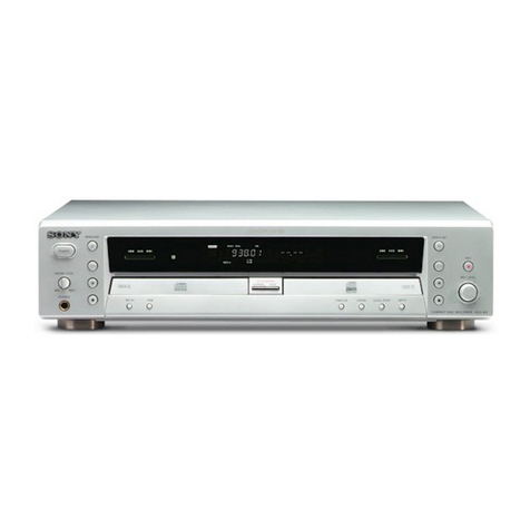
RCD-W222ES
TABLE OF CONTENTS
1. SERVICING NOTE .......................................................... 4
2. GENERAL .......................................................................... 7
3. DISASSEMBLY
3-1. Case (Top) ............................................................................ 8
3-2. Front Panel Section ..............................................................9
3-3. Power SW board, HP board, RM board,
LED board, CD SW board, Display Board .......................... 9
3-4. Deck A (CDM53L-30B61B), Deck B (CDM65-RBD1) ... 10
3-5. CD-R Board, Tray And Optical Pick-Up Block
(KRM-220) (Deck B)......................................................... 11
3-6. CD Base Unit (BU-30BBD61B) (Deck A) ........................ 12
3-7. Fitting Base (Guide) Assy, Bracket (Chassis)
And Magnet Assy (Deck A) ............................................... 12
3-8. Tray (Sub) (Deck A) .......................................................... 13
3-9. Chassis (Mold B) Section, Stocker Section
And Slider (Selection)........................................................ 13
4. ASSEMBLY ....................................................................... 14
5.TEST MODE...................................................................... 17
6. ELECTRICAL ADJUSTMENT ................................... 20
7. DIAGRAMS
7-1. Circuit Boards Location .................................................... 51
7-2. Block diagrams – BD Section –........................................ 52
Block diagrams – CD-R Section – .................................... 53
Block diagrams – MAIN Section –................................... 54
7-3. Schematic Diagram – CD-R (1/3) Section –..................... 55
7-4. Schematic Diagram – CD-R (2/3) Section –..................... 56
7-5. Schematic Diagram – CD-R (3/3) Section –..................... 57
7-6. Printed Wiring Board – CD-R Section (Side A) – ............ 58
Printed Wiring Board – CD-R Section (Side B) – ............ 59
7-7. Printed Wiring Board – BD Section –............................... 60
7-8. Schematic Diagram – BD Section – ................................ 61
7-9. Printed Wiring Board – CDM Section – ........................... 62
7-10. Schematic Diagram – CDM Section – ............................. 63
7-11. Printed Wiring Board – MAIN Section (Side A) – ........... 64
Printed Wiring Board – MAIN Section (Side B) – ........... 65
7-12. Schematic Diagram – MAIN (1/2) Section –................... 66
7-13. Schematic Diagram – MAIN (2/2) Section –................... 67
7-14. Printed Wiring Board – LED, HP Section –...................... 68
7-15. Schematic Diagram – LED, HP Section – ....................... 69
7-16. Printed Wiring Board – Display, Power Section – ............ 70
7-17. Schematic Diagram – Display, Power Section –............... 71
7-18. IC Pin Functions................................................................ 72
7-19. IC Block Diagrams............................................................ 83
8. EXPLODEDVIEWS
8-1. Case Section ........................................................................ 85
8-2. Front Panel Section ............................................................. 86
8-3. Chassis Section ................................................................... 87
8-4. CD Play Mechanism Section (Deck A)-1
(CDM53L-30B61B)........................................................... 88
8-5. CD Play Mechanism Section (Deck A)-2
(CDM53L-30B61B)........................................................... 89
8-6. CD Play Mechanism Section (Deck A)-3
(CDM53L-30B61B)........................................................... 90
8-7. Stocker Overall, Optical Pick-Up Section (Deck A) .......... 91
8-8. Base Unit (Deck A) ............................................................. 92
8-9. CD-R Mechanism Deck Section (Deck B) ......................... 93
9. ELECTRICAL PARTS LIST .................................94
SELF-DIAGNOSIS FUNCTION
When the self-diagnosis function is activated to prevent the player from
malfunctioning, three character service numbers in a combination with a
message appears in the display. In this case, check the following table.
Message Explanation
C12/ You are trying to record a disc that cannot be played
Cannot Copy back in DECK-A or with an external device, such
as CD-ROM or VIDEO CD.
• Remove the disc, and then insert a music CD for
playback.
C13/ Recording has not been completed successfully be-
Rec Error cause of vibration.
• Relocate the unit in a place free of vibration and
restart the recording again.
The disc you try to record is excessively dirty (such
as oilstained or finger marked) or scratched. Or the
disc is not normal.
• Replace the disc with another one and restart the
recording again.
C14/ The unit did not read the TOC information.
TOC Error • Insert other discs.
C41/ The sound source you are trying to record is a copy
Cannot Copy of a commercial music software. Or you are trying
to record on a CD-R/CD-RW digitally.
• Because of the restriction of the Serial Copy Man-
agement System, you cannot record a copy of a
commercial music software.
Neither can you record a CD-R/ CD-RW digitally.
• Use analog recording through the ANALOG IN
jack when you record from other units. Or use Syn-
chro-Recording when you record from DECK A.
(The recording mode is automatically changed to
analog recording.)
C71/ If this message is displayed momentarily, this is not
Din Unlock an error. It is caused by the digital signal during re-
cording. During recording of a digital sound source, the con-
necting cable has been disconnected or the player of
the sound source has turned off.
• Connect the cable or turn on the digital player.


