7
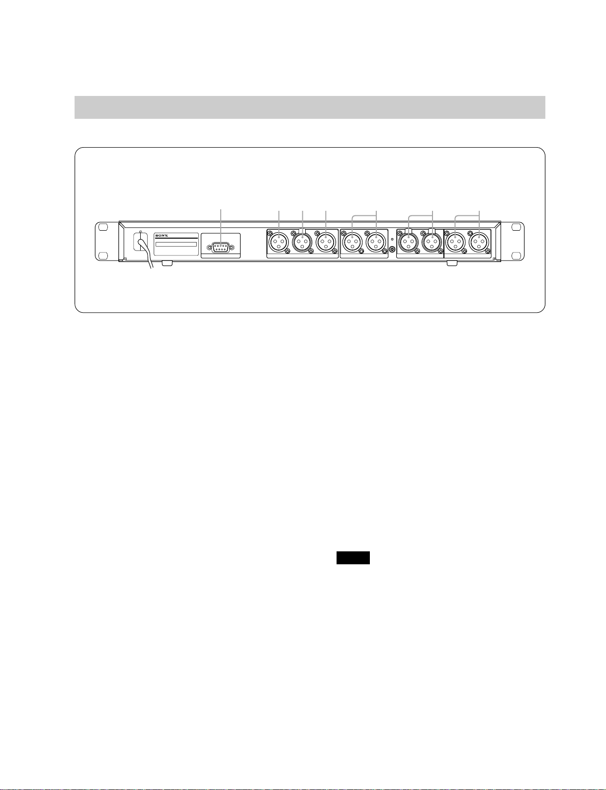
3. CONTROLS AND FUNCTIONS
3-1. Front Panel
POWER
ON OFF
0
−12 +12
dB
0
−12 +12
dB
0
−12 +12
dB
0
−12 +12
dB
INPUT LEVEL
CH-1 CH-2
OVER
OUTPUT LEVEL
CH-1 CH-2
INPUT
ANALOG
DIGITAL
PLL
LIMITER / DELAY
1
OVER/GR(dB)
36912151821242730
-
CH-1
CH-2
−+
ADJUST
−+
SELECT
PUSH ENTER/YES
EDIT PROGRAM
SYNC EXIT/NO
LOCK
BYPASS
DIGITAL LIMITER/DELAY SRP-L300
1
2
3
46
57 98 %#!
"$&
1POWER button
This POWER button turns on and off the power of
the SRP-L300.
When the power is turned on, the back light on the
display screen lights and the previous signal
processing condition returns automatically.
2INPUT LEVEL knobs (CH-1 and CH-2)
The INPUT LEVEL knobs are used to adjust the
level of the input signals from the analog input
terminals.
In the center position (0 dB), a internally head room
is 20 dB with respect to the input signal of a
reference level (+4 dBs).
For how to adjust these knobs, refer to 5-2, “Level
Diagram”and 5-3, “Unity Gain.”
3OVER indicators (CH-1 and CH-2)
The OVER indicators light when signals exceeding
the maximum input level are input from the analog
input terminals.
Actually, the OVER indicators light from the level
slightly lower than the level in which a signal is
clipped.
Decrease the level using the INPUT LEVEL knobs
when they light frequently.
4OUTPUT LEVEL knobs (CH-1 and CH-2)
The OUTPUT LEVEL knobs are used to adjust the
level of the output signals from the analog output
terminals.
In the center position (0 dB), the digital full scale
output signal for digital signal processing is output
in a level of +24 dBu.
To adjust these knobs, refer to 5-2, “Level Diagram”
and 5-3, “Unity Gain.”
Note
5INPUT indicator
The input indicator selected by internal parameter
“Input Select”lights. In the analog and digital
mixing state, both the ANALOG and DIGITAL
lamps light.
For more details of the input selection, refer to 6-1,
“Input Block.”
6PLL indicator
The PLL indicator indicates that a digital signal is
properly transmitted and that the SRP-L300 receives
it.
Moreover, this indicator indicates the existence of
physical transmission. The PLL indicator also lights
when a silent signal is being transmitted because it
is not related to the level of an audio signal.
“PLL”is an abbreviation for Phase-Locked Loop.
The circuit that operates in synchronization with a
digital input signal is called a PLL circuit. The PLL
indicator lights when the PLL circuit operates
normally.
7Display
The display is used the user setting state or level
meter with a character display of 16 characters ×2
lines.
The back light goes on when the power is turned on.
8SELECT knob and SELECT (ENTER/YES)
button
Operate the knob and button as described below if
necessary.
Turn clockwise or counterclockwise.
Press.
Turn while pressing and holding.
The meaning of the operation varies depending on
the state at that time.