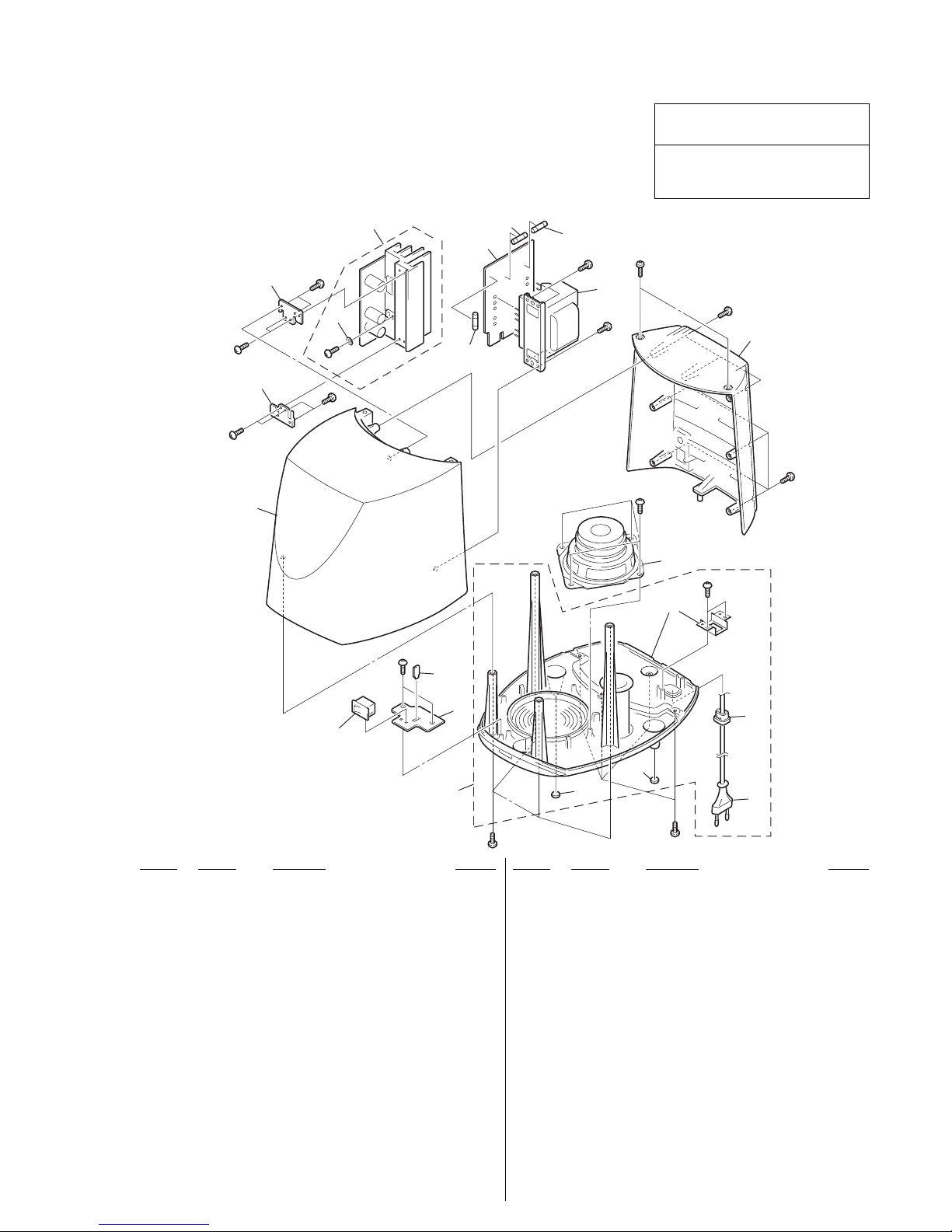
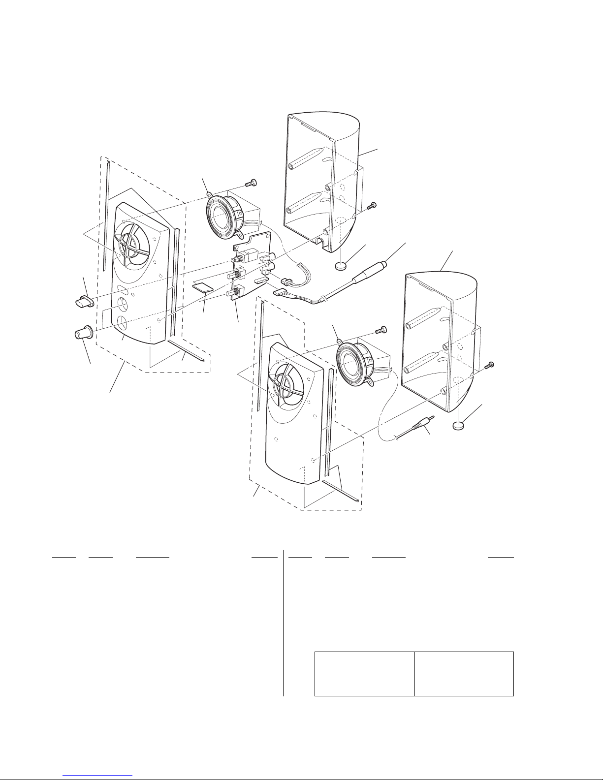
Sony SRS-D101 User manual

Sony Corporation
Personal Audio Company
Published by Sony Engineering Corporation
9-873-998-02
2002K1600-1
© 2002.11
SRS-D101
US Model
Canadian Model
AEP Model
UK Model
E Model
Australian Model
SERVICE MANUAL
ACTIVE SPEAKER SYSTEM
SPECIFICATIONS
Ver 1.1 2002. 11
Front speakers
Speaker system Full range, magnetically shielded
Speaker units 3.9 cm, cone type
Enclosure type Bass reflex
Impedance 6 Ω
Power handling capacity 3 watts
Maximum input power 6 watts
Sensitivity level 81 dB (1 W, 1 m)
Dimensions (w/h/d) 54 ×115 ×74 mm
Mass 210 g (Lch), 160 g (Rch)
Cord length 2 m
Input impedance 4.7 kΩ (at 1 kHz)
Input LINE IN 1, 2
Subwoofer
Speaker system
Active subwoofer, magnetically shielded
Speaker unit 9 cm, cone type
Enclosure type Bass reflex
Impedance 6 Ω
Power handling capacity 14 watts
Maximum input power 28 watts
Sensitivity level 80 db (1 W, 1 m)
Dimensions (w/h/d) 194 ×210 ×239 mm
Mass 2,400 g
Amplifier section
Rated output:
Woofer section 14 W <
10 % T.H.D., 100 Hz, 6 Ω
>
Mid and high range section
3 W + 3 W <
10 % T.H.D., 1 kHz, 6 Ω
>
Total
20 W
General
Power consumptions 20 W
Cord length 2 m (adaptor cable)
Supplied accessories
Audio connecting cord (1)
Design and specifications are subject to change
without notice.
Where purchased Operating voltage
U.S.A./Canada 120 V AC, 60 Hz
European countries 220-230 V AC, 50Hz
Other countries • 110 – 120 V AC, 50/60Hz
•220 – 230 V AC, 50 Hz

2
SRS-D101
SAFETY CHECK-OUT
After correcting the original service problem, perform the following
safety check before releasing the set to the customer:
Check the antenna terminals, metal trim, “metallized” knobs, screws,
and all other exposed metal parts for AC leakage.
Check leakage as described below.
LEAKAGE TEST
The AC leakage from any exposed metal part to earth ground and
from all exposed metal parts to any exposed metal part having a
return to chassis, must not exceed 0.5 mA (500 microamperes.).
Leakage current can be measured by any one of three methods.
1. A commercial leakage tester, such as the Simpson 229 or RCA
WT-540A. Follow the manufacturers’ instructions to use these
instruments.
2. A battery-operated AC milliammeter. The Data Precision 245
digital multimeter is suitable for this job.
3. Measuring the voltage drop across a resistor by means of aVOM
or battery-operatedAC voltmeter. The “limit” indication is 0.75
V, so analog meters must have an accurate low-voltage scale.
The Simpson 250 and Sanwa SH-63Trd are examples of a
passive VOM that is suitable. Nearly all battery operated digital
multimeters that have a 2 V AC range are suitable. (See Fig. A)
To Exposed Metal
Parts on Set
0.15 µF1.5 kΩ
AC
Voltmeter
(0.75V)
Earth Ground
Fig.A. Using an AC voltmeter to check AC leakage.
SAFETY-RELATED COMPONENT WARNING!!
COMPONENTS IDENTIFIED BY MARK 0OR DOTTED LINEWITH
MARK 0ON THE SCHEMATIC DIAGRAMS AND IN THE PARTS
LIST ARE CRITICAL TO SAFE OPERATION. REPLACE THESE
COMPONENTS WITH SONY PARTS WHOSE PART NUMBERS
APPEAR AS SHOWN IN THIS MANUAL OR IN SUPPLEMENTS
PUBLISHED BY SONY.
ATTENTION AU COMPOSANT AYANT RAPPORT
À LA SÉCURITÉ!
LES COMPOSANTS IDENTIFÉS PAR UNE MARQUE 0SUR LES
DIAGRAMMES SCHÉMATIQUES ET LA LISTE DES PIÈCES SONT
CRITIQUES POUR LA SÉCURITÉ DE FONCTIONNEMENT. NE
REMPLACER CES COMPOSANTS QUE PAR DES PIÈSES SONY
DONT LES NUMÉROS SONT DONNÉS DANS CE MANUEL OU
DANS LES SUPPÉMENTS PUBLIÉS PAR SONY.
Notes on chip component replacement
•Never reuse a disconnected chip component.
•Notice that the minus side of a tantalum capacitor may be
damaged by heat.

3
SRS-D101
SECTION 1
GENERAL This section is extracted from
instruction manual.
Precautions
On safety
The nameplate indicating operating voltage, power
consumption, etc. is located on the bottom exterior.
•
Before operating the system, be sure that the operating voltage
of the system is identical with that of your local power supply.
Where purchased Operating voltage
U.S.A./Canada 120 V AC, 60 Hz
European countries 220-230 V AC, 50Hz
Other countries • 110 – 120 V AC, 50/60Hz
• 220 – 230 V AC, 50 Hz
•
The unit is not disconnected from the AC power source (mains)
as long as it is connected to the wall outlet, even if the unit
itself has been turned off.
•
Unplug the system from the wall outlet if it is not to be used for
an extended period of time. To disconnect the cord, pull the
cord by grasping the plug. Never pull the cord itself.
•
Should any liquid or solid object fall into the system, unplug
the system’s power cord and have the system checked by
qualified personnel before operating it any further.
•
The AC power cord should be changed only at a qualified
service shop.
•
For efficient heat dissipation, ensure there is sufficient space to
the rear of the woofer. Also, avoid placing objects on the unit.
On operation
•
Do not drive the speaker system with a continuous wattage
exceeding the maximum input power of the system.
•
Contact between bare speaker wires at the speaker terminals
may result in a short-circuit.
•
Before connecting, turn off the Speaker system, the PC and the
audio component to avoid damaging the speaker system.
•
The volume level should not be turned up to the point of
distortion.
Hooking up the system
1
(See fig. Afor steps 1 through 3.)
Connect the left speaker cord 8 pin plug to the rear
panel jack with their respective arrows aligned.
2
Connect the subwoofer to the wall outlet.
3
Connect the CD walkman, PC, etc., to the INPUT
jack on the left speaker.
4
Position the speakers. (See fig. B.)
Note on connecting
Do not connect an output device to INPUT 1 and INPUT 2
of the unit at the same time (as shown in fig. C) to avoid
damage to the output device.
Listening to the sound (see fig. D)
First, turn down the volume on the left speaker. The volume
should be set to minimum before you begin playing the
programme source.
1
Press POWER on the left speaker.
The POWER indicator lights up green.
For the European models
Press POWER on the subwoofer to turn it on, and then
press OPERATE on the left speaker.
The OPERATE indicator lights up green.
The main power source of the system is provided by the
subwoofer. When the power of the subwoofer is turned off,
the system does not operate, even if OPERATE is pressed.
2
Play the programme source.
To adjust the volume
Rotate VOLUME.
To adjust the subwoofer
Rotate BASS to adjust the bass volume.
Set the volume level to best suit your preference according to the
programme source.
Notes
• To enjoy high-quality sound, do not turn the bass
volume too high.
•When two units are connected to the system and the
programme sources are played at the same time, their
playback sounds will be mixed up. In this case, turn off
one of the units not in use.
OFF ON
SRS-D101
ACTIVESPEAKER SYSTEM
BASS
MIN MAX
VOLUME
OPERATE
MIN
ON
OFF
MAX
SRS-D101
ACTIVESPEAKER SYSTEM
ROUT
LOUT
INPUT
1
2
B
A
Front (Right)/Avant (droite)
Vorne (rechts)/Parte frontal (derecha)
Subwoofer
Caisson de grave
Tiefsttonlautsprecher
Potenciación de graves
Front (Right)
Avant (droite)
Vorne (rechts)
Parte frontal (derecha)
Front (Left)
Avant (gauche)
Vorne (links)
Parte frontal (izquierda)
POWER
(OPERATE for European model)
(OPERATE pour le modèle européen)
(OPERATE beim Modell für Europa)
(OPERATE para el modelo europeo)
BASS
VOLUME
Note PC
PC Note
Notebook-PC
Portátil
Front (Left)/Avant (gauche)
Vorne (links)/Parte frontal (izquierda)
PC/Ordinateur
PC/PC
CD Walkman
Walkman CD
CD-Walkman
CD Walkman
to 8 pin Din jack
vers la prise Din à 8 broches
an 8 polige DIN-Buchse
a conector DIN de 8 patillas
to Mono Mini jack
vers la mini prise mono
an Monominibuchse
a mini toma mono to wall outlet
vers la prise murale
an eine Netzsteckdose
a la toma de corriente
*
*This switch is only for
European models.
Cet interrupteur ne concerne
que les modèles européens.
Dieser Schalter ist nur für
Modelle für Europa.
Este interruptor sólo está
destinado a los modelos
europeos.
D
Subwoofer
Caisson de grave
Tiefsttonlautsprecher
Potenciación de graves
CIncorrect connection/Raccordement incorrect/Falscher Anschluß/
Conexión incorrecta
ROUT
LOUT
INPUT
1
2
Head phone output, etc.
Sortie de casque d’écoute, etc.
Kopfhörerausgang usw.
Salida de auricular, etc.
USB, etc.
Port USB, etc.
USB usw.
USB, etc.
Network Walkman, etc./Network
Walkman, etc./Network Walkman
usw./Network Walkman, etc.
Head phone output, etc.
Sortie de casque d’écoute, etc.
Kopfhörerausgang usw.
Salida de auricular, etc.
BASS
MIN MAX
VOLUME
POWER
MIN
ON
OFF
MAX

4
SRS-D101 SECTION 2
DIAGRAMS
• IC Block Diagrams IC301 LA4601N
10
7
9
8
65
1
2
4
3
R-IN
PRE-GND
L-IN
STBY
Standby switching
CH1 input
amplifier
CH2 input
amplifier
REF
amplifier
Predrive
amplifier
Predrive
amplifier
TSD protector
Output
amplifier
Output
amplifier
FILTERP. P
POWER
GND
R-OUT
L-OUT
Vcc
Pop noise prevention block
Ripple filter
IC302 LM4701T

55
SRS-D101
2-1. Printed Wiring Board – AMP Section –
IC303
IC301
IC302
B
TO
CONTROL
BOARD
CN102
(Page 6)
(Page 7)
AEP, UK, AUS
J301 L OUT
Note on Printed Wiring Boards:
•X: parts extracted from the component side.
•b: Pattern from the side which enables seeing.
Ref. No. Location
D301 B-3
IC301 B-4
IC302 B-2
IC303 B-3
Q301 B-1
Q302 B-1
Q303 B-1
Q304 B-3
Q305 B-3
• Semiconductor
Location
Ver 1.1 2002.11

66
SRS-D101
2-2. Printed Wiring Board – CONTROL Section –
IC102
IC101
BTO
AMPLIFIER BOARD
J301
(Page 5)
Note on Printed Wiring Boards:
•X: parts extracted from the component side.
•b: Pattern from the side which enables seeing.

77
SRS-D101
2-3. Printed Wiring Board – POWER Section –
5
AEP, UK, AUS
AEP, UK, AUS
Note on Printed Wiring Boards:
•X: parts extracted from the component side.
•b: Pattern from the side which enables seeing.
Ref. No. Location
D901 A-2
D902 A-3
D903 A-3
D904 A-2
D905 A-1
D906 A-2
D907 A-1
D908 A-1
• Semiconductor
Location
Ver 1.1 2002.11

88
SRS-D101
2-4. Schematic Diagra – ALL Section – • See page 4 for IC Block Diagrams.
Note on Schematic Diagram:
•All capacitors are in µF unless otherwise noted. pF:
µµF 50 WV or less are not indicated except for
electrolytics and tantalums.
•All resistors are in Ωand 1/4W or less unless other-
wise specified.
•C: panel designation.
•A: B+ Line.
•B: B– Line. The components identified by
mark 0or dotted line with mark
0are critical for safety.
Replace only with part number
specified.
Les composants identifiés par
une marque 0sont critiques
pour la sécurité.
Ne les remplacer que par une
pièce portant le numéro spécifié.
AUS
AUS
AUS
AUS
AUS
AUS
•Voltages is dc with respect to ground under no-sig-
nal (detuned) conditions.
•Voltages are taken with a VOM (Input impedance
10 MΩ).
Voltage variations may be noted due to normal pro-
duction tolerances.
•Signal path.
E: AUDIO signal
•Abbreviation
CND : Canadian model.
E92 : Chilean and Peruvian model.
SP : Singapore model.
AUS:Australian model.
Ver 1.1 2002.11

9
SRS-D101
NOTE:
•Items marked “*” are not stocked since they
are seldom required for routine service. Some
delay should be anticipated when ordering these
items.
•The mechanical parts with no reference number
in the exploded views are not supplied.
•Accessories are given in the last of this parts
list.
•Abbreviation
CND : Canadian model.
E92 : Chilean and Peruvian model.
SP : Singapore model.
AUS:Australian model.
The components identified by mark 0or
dotted line with mark 0are critical for safety.
Replace only with part number specified.
Les composants identifiés par une marque
0sont critiques pour la sécurité.
Ne les remplacer que par une pièce portant
le numéro spécifié.
SECTION 3
EXPLODED VIEWS
Ref. No. Part No. Description Remarks Ref. No. Part No. Description Remarks
3-1. AMP Section
*11-684-829-21 POWER SWITCH BOARD (AEP,UK,AUS)
*21-684-830-21 RETAINER BOARD (SW) (AEP,UK,AUS)
*31-684-828-11 RETAINER BOARD(US,CND,E92)
*31-684-828-21 RETAINER BOARD (AEP,UK,SP,AUS)
4X-3381-972-1 CABINET SUB (UPPER) ASSY (US,CND)
4X-3382-212-1 CABINET SUB ASSY (UPPER) (AEP,UK,AUS)
4X-3382-215-1 CABINET SUB ASSY (UPPER) (E92,SP)
*5A-3323-717-A AMPLIFIER BOARD, COMPLETE (US,CND,E92)
*5A-3323-992-A AMPLIFIER BOARD, COMPLETE (AEP,UK,AUS)
*5A-3323-997-A AMPLIFIER BOARD, COMPLETE (SP)
*61-684-827-11 POWER BOARD (US,CND,E92)
*61-684-827-21 POWER BOARD (AEP,UK,SP,AUS)
73-240-834-01 PANEL, REAR (US,CND)
73-240-834-11 PANEL, REAR (AEP,UK,SP,E92,AUS)
84-217-350-11 STOPPER, CORD
091-696-848-42 CORD, POWER (AUS)
091-696-169-11 CORD, POWER (AEP,UK,SP)
091-775-789-91 CORD, POWER (E92)
091-783-531-11 CORD, POWER (US,CND)
10 3-232-664-01 FOOT, RUBBER
11 X-3381-973-1 BASE SUB ASSY, WOOFER (US,CND)
11 X-3382-213-1 BASE SUB ASSY, WOOFER (AEP,UK)
11 X-3382-217-2 BASE SUB ASSY, WOOFER (E92)
11 X-3382-218-1 BASE SUB ASSY, WOOFER (SP)
11 X-3382-884-1 BASE SUB ASSY, WOOFER (AUS)
12 4-217-354-11 BUSHING, INSULATING
0F901 1-533-468-11 FUSE, GLASS TUBE (DIA. 5) T2.0AL/250V
(AEP,UK,SP,AUS)
0F901 1-576-478-11 FUSE, GLASS TUBE 2.0A/125V (US,CND,E92)
0F902 1-533-448-11 FUSE, GLASS TUBE (DIA. 5) 1.6A/125V
(US,CND,E92)
0F902 1-533-467-11 FUSE, GLASS TUBE (DIA. 5) T1.6AL/250V
(AEP,UK,SP,AUS)
0F903 1-533-448-11 FUSE, GLASS TUBE (DIA. 5) 1.6A/125V
(US,CND,E92)
0F903 1-533-467-11 FUSE, GLASS TUBE (DIA. 5) T1.6AL/250V
(AEP,UK,SP,AUS)
S901 1-771-762-11 SWITCH, POWER (POWER SWITCH)
(AEP,UK,AUS)
SP103 1-825-139-11 SPEAKER (090W005//C)
0T901 1-437-745-11 TRANSFORMER, POWER (US,CND,E92)
0T901 1-437-746-11 TRANSFORMER, POWER (AEP,UK,SP,AUS)
#3 7-685-547-19 SCREW +BTP 3X10 TYPE2 N-S
#4 7-685-647-79 SCREW +BVTP 3X10 TYPE2 SLIT
#5 7-685-646-79 SCREW +P 3X8 TYPE2 NON-SLIT
SP103
not
supplied
#4
#4
#4
#4
#4
#4
#4
#5
#4
10
10
2
4
1
11
5
7
3
12
3
6
#4
8
9
#4
#3
F901
F902
F903
S901
#4
#
4
#4
T901
Ver 1.1 2002.11

10
SRS-D101
Ref. No. Part No. Description Remarks Ref. No. Part No. Description Remarks
3-2. Speaker Section
58
51
52
53
54
61
55
56
#1
#1
#2
#2
SP101
SP102
55
57 59
60
not
supplied
not
supplied
not
supplied
not
supplied
not
supplied
51 X-3382-051-1 CABINET (L) SUB ASSY, FRONT
(US,CND,E92,SP)
51 X-3382-214-1 CABINET (L) SUB ASSY, FRONT (AEP,UK,AUS)
52 3-240-839-01 BUTTON, POWER
53 3-240-840-01 KNOB
*54 A-3323-720-A CONTROL BOARD, COMPLETE (US,CND,E92)
*54 A-3323-995-A CONTROL BOARD, COMPLETE (AEP,UK,SP,AUS)
55 3-232-664-01 FOOT, RUBBER
56 3-240-837-01 CABINET, REAR (L)
57 1-823-971-11 DIN CABLE 8P
58 X-3382-052-1 CABINET (R) SUB ASSY, FRONT
59 3-240-838-01 CABINET, REAR (R)
60 1-823-970-11 CORD CONNECTION 1P
*61 1-685-052-21 LED BOARD
SP101 1-825-140-11 SPEAKER (039F008//C)
SP102 1-825-140-11 SPEAKER (039F008//C)
#1 7-685-105-19 SCREW +P 2X8 TYPE2 NON-SLIT
#2 7-685-133-19 SCREW +P 2.6X6 TYPE2
The components identified by
mark 0or dotted line with mark
0are critical for safety.
Replace only with part number
specified.
Les composants identifiés par
une marque 0sont critiques
pour la sécurité.
Ne les remplacer que par une
pièce portant le numéro spécifié.
Ver 1.1 2002.11

11
The components identified by mark 0or
dotted line with mark 0are critical for safety.
Replace only with part number specified.
Les composants identifiés par une marque
0sont critiques pour la sécurité.
Ne les remplacer que par une pièce portant
le numéro spécifié.
SRS-D101
NOTE:
•Due to standardization, replacements in the
parts list may be different from the parts
specified in the diagrams or the components
used on the set.
•Items marked “*” are not stocked since they
are seldom required for routine service.
Some delay should be anticipated when
ordering these items.
•RESISTORS
All resistors are in ohms.
METAL: metal-film resistor
METAL OXIDE: Metal Oxide-film resistor
F: nonflammable
•SEMICONDUCTORS
In each case, u: µ, for example:
uA...: µA... , uPA... , µPA... ,
uPB... , µPB... , uPC... , µPC... ,
uPD..., µPD...
•CAPACITORS:
uF: µF
•Abbreviation
CND : Canadian model.
E92 : Chilean and Peruvian model.
SP : Singapore model.
AUS:Australian model.
When indicating parts by reference number,
please include the board name.
•COILS
uH: µH
SECTION 4
ELECTRICAL PARTS LIST AMPLIFIER
*A-3323-717-A AMPLIFIER BOARD, COMPLETE (US,CND,E92)
*A-3323-992-A AMPLIFIER BOARD, COMPLETE (AEP,UK,AUS)
*A-3323-997-A AMPLIFIER BOARD, COMPLETE (SP)
**************************
4-217-354-11 BUSHING, INSULATING
7-685-646-79 SCREW +P 3X8 TYPE2 NON-SLIT
7-685-647-79 SCREW +BVTP 3X10 TYPE2 SLIT
< CAPACITOR >
C117 1-130-488-00 MYLAR 0.027uF 5% 50V
C119 1-126-934-11 ELECT 220uF 20.00% 16V
C217 1-130-488-00 MYLAR 0.027uF 5% 50V
C219 1-126-934-11 ELECT 220uF 20.00% 16V
C332 1-126-959-11 ELECT 0.47uF 20.00% 50V
C333 1-126-933-11 ELECT 100uF 20.00% 16V
C338 1-126-933-11 ELECT 100uF 20.00% 16V
C339 1-124-234-00 ELECT 22uF 20% 16V
C340 1-126-960-11 ELECT 1uF 20.00% 50V
C341 1-126-947-11 ELECT 47uF 20.00% 16V
C342 1-130-499-00 MYLAR 0.22uF 5% 50V
C343 1-162-964-11 CERAMIC CHIP 0.001uF 10% 50V
C344 1-162-964-11 CERAMIC CHIP 0.001uF 10% 50V
C345 1-162-927-11 CERAMIC CHIP 100PF 5% 50V
C346 1-162-927-11 CERAMIC CHIP 100PF 5% 50V
C347 1-107-826-11 CERAMIC CHIP 0.1uF 10.00% 16V
C350 1-126-953-11 ELECT 2200uF 20.00% 35V
C351 1-126-953-11 ELECT 2200uF 20.00% 35V
C352 1-126-944-11 ELECT 3300uF 20.00% 25V
< CONNECTOR >
CN302 1-566-690-11 PLUG, CONNECTOR (2.5mm) 2P
< DIODE >
D301 8-719-423-10 DIODE MA8100-M-TX (AEP,UK,AUS)
< IC >
IC301 8-759-543-56 IC LA4601N
IC302 6-702-348-01 IC LM4701T
IC303 6-700-776-01 IC KIA78S09P-TP
< JACK >
J301 1-417-224-11 CONNECTOR, DIN (SOCKET) 8P (L OUT)
J302 1-566-822-51 JACK (R OUT)
< TRANSISTOR >
Q301 8-729-038-67 TRANSISTOR KRC102S
Q302 8-729-038-67 TRANSISTOR KRC102S
Q303 8-729-038-71 TRANSISTOR KRC107S
Q304 8-729-920-31 TRANSISTOR DTC343TK-T-146
(AEP,UK,AUS)
Q305 8-729-038-71 TRANSISTOR KRC107S (AEP,UK,AUS)
< RESISTOR >
R118 1-216-829-11 METAL CHIP 4.7K 5% 1/16W
R119 1-216-818-11 METAL CHIP 560 5% 1/16W
R218 1-216-829-11 METAL CHIP 4.7K 5% 1/16W
R219 1-216-818-11 METAL CHIP 560 5% 1/16W
R332 1-216-833-11 METAL CHIP 10K 5% 1/16W
R333 1-216-829-11 METAL CHIP 4.7K 5% 1/16W
R335 1-216-821-11 METAL CHIP 1K 5% 1/16W
R336 1-216-841-11 METAL CHIP 47K 5% 1/16W
R337 1-216-833-11 METAL CHIP 10K 5% 1/16W
R338 1-216-829-11 METAL CHIP 4.7K 5% 1/16W
R339 1-216-837-11 METAL CHIP 22K 5% 1/16W
R340 1-216-829-11 METAL CHIP 4.7K 5% 1/16W
R341 1-216-821-11 METAL CHIP 1K 5% 1/16W
R342 1-216-841-11 METAL CHIP 47K 5% 1/16W
R343 1-216-821-11 METAL CHIP 1K 5% 1/16W
R344 1-216-837-11 METAL CHIP 22K 5% 1/16W
R345 1-216-308-00 METAL CHIP 4.7 5% 1/10W
R346 1-216-308-00 METAL CHIP 4.7 5% 1/10W
R347 1-216-833-11 METAL CHIP 10K 5% 1/16W
(AEP,UK,AUS)
R348 1-216-845-11 METAL CHIP 100K 5% 1/16W
(AEP,UK,AUS)
R349 1-216-829-11 METAL CHIP 4.7K 5% 1/16W
(AEP,UK,AUS)
************************************************************
*A-3323-720-A CONTROL BOARD, COMPLETE (US,CND,E92)
*A-3323-995-A CONTROL BOARD, COMPLETE
(AEP,UK,SP,AUS)
*************************
< CAPACITOR >
C101 1-126-963-11 ELECT 4.7uF 20.00% 50V
C103 1-126-963-11 ELECT 4.7uF 20.00% 50V
C106 1-126-964-11 ELECT 10uF 20.00% 50V
C107 1-162-927-11 CERAMIC CHIP 100PF 5% 50V
C109 1-126-963-11 ELECT 4.7uF 20.00% 50V
C110 1-126-963-11 ELECT 4.7uF 20.00% 50V
C111 1-126-963-11 ELECT 4.7uF 20.00% 50V
CONTROL
Ref. No. Part No. Description Remarks Ref. No. Part No. Description Remarks
Ver 1.1 2002.11

Ref. No. Part No. Description Remarks Ref. No. Part No. Description Remarks
12
SRS-D101
C131 1-126-963-11 ELECT 4.7uF 20.00% 50V
C201 1-126-963-11 ELECT 4.7uF 20.00% 50V
C203 1-126-963-11 ELECT 4.7uF 20.00% 50V
C206 1-126-964-11 ELECT 10uF 20.00% 50V
C207 1-162-927-11 CERAMIC CHIP 100PF 5% 50V
C209 1-124-259-11 ELECT 4.7uF 20.00% 16V
C210 1-124-259-11 ELECT 4.7uF 20.00% 16V
C211 1-126-963-11 ELECT 4.7uF 20.00% 50V
C231 1-124-259-11 ELECT 4.7uF 20.00% 16V
C301 1-126-933-11 ELECT 100uF 20.00% 16V
C302 1-107-826-11 CERAMIC CHIP 0.1uF 10.00% 16V
C303 1-126-933-11 ELECT 100uF 20.00% 16V
C304 1-107-826-11 CERAMIC CHIP 0.1uF 10.00% 16V
C307 1-131-664-91 CERAMIC CHIP 0.15uF 10% 10V
C309 1-107-826-11 CERAMIC CHIP 0.1uF 10.00% 16V
C310 1-126-963-11 ELECT 4.7uF 20.00% 50V
C311 1-126-964-11 ELECT 10uF 20.00% 50V
C312 1-107-826-11 CERAMIC CHIP 0.1uF 10.00% 16V
C313 1-107-826-11 CERAMIC CHIP 0.1uF 10.00% 16V
C314 1-127-715-91 CERAMIC CHIP 0.22uF 10% 16V
C315 1-126-963-11 ELECT 4.7uF 20.00% 50V
C316 1-162-927-11 CERAMIC CHIP 100PF 5% 50V
C321 1-126-964-11 ELECT 10uF 20.00% 50V
< CONNECTOR >
CN101 1-566-690-11 PLUG, CONNECTOR (2.5mm) 2P
*CN102 1-506-990-11 PIN, CONNECTOR (PC BOARD) 8P
< IC >
IC101 8-759-502-82 IC LM324M-FL63
IC102 8-759-100-96 IC NJM4558M-TE2
< JACK >
J101 1-566-822-51 JACK (INPUT 1)
J102 1-566-822-51 JACK (INPUT 2)
< JUMPER RESISTOR >
JR101 1-216-864-11 METAL CHIP 0 5% 1/16W
JR102 1-216-864-11 METAL CHIP 0 5% 1/16W
< TRANSISTOR >
Q101 8-729-038-71 TRANSISTOR KRC107S
Q102 8-729-038-58 TRANSISTOR KRA107S
< RESISTOR >
R101 1-216-827-11 METAL CHIP 3.3K 5% 1/16W
R103 1-216-821-11 METAL CHIP 1K 5% 1/16W
R104 1-216-827-11 METAL CHIP 3.3K 5% 1/16W
R105 1-216-829-11 METAL CHIP 4.7K 5% 1/16W
R106 1-216-829-11 METAL CHIP 4.7K 5% 1/16W
R107 1-216-837-11 METAL CHIP 22K 5% 1/16W
R108 1-216-833-11 METAL CHIP 10K 5% 1/16W
R109 1-216-837-11 METAL CHIP 22K 5% 1/16W
R131 1-216-827-11 METAL CHIP 3.3K 5% 1/16W
R201 1-216-827-11 METAL CHIP 3.3K 5% 1/16W
R203 1-216-821-11 METAL CHIP 1K 5% 1/16W
R204 1-216-827-11 METAL CHIP 3.3K 5% 1/16W
R205 1-216-829-11 METAL CHIP 4.7K 5% 1/16W
R206 1-216-829-11 METAL CHIP 4.7K 5% 1/16W
R207 1-216-837-11 METAL CHIP 22K 5% 1/16W
R208 1-216-833-11 METAL CHIP 10K 5% 1/16W
R209 1-216-837-11 METAL CHIP 22K 5% 1/16W
R231 1-216-827-11 METAL CHIP 3.3K 5% 1/16W
R301 1-216-829-11 METAL CHIP 4.7K 5% 1/16W
R302 1-216-807-11 METAL CHIP 68 5% 1/16W
R303 1-216-829-11 METAL CHIP 4.7K 5% 1/16W
R305 1-216-829-11 METAL CHIP 4.7K 5% 1/16W
R306 1-216-833-11 METAL CHIP 10K 5% 1/16W
R307 1-216-833-11 METAL CHIP 10K 5% 1/16W
R308 1-216-821-11 METAL CHIP 1K 5% 1/16W
R309 1-216-833-11 METAL CHIP 10K 5% 1/16W
R310 1-216-823-11 METAL CHIP 1.5K 5% 1/16W
R311 1-216-845-11 METAL CHIP 100K 5% 1/16W
R312 1-216-854-11 METAL CHIP 560K 5% 1/16W
R313 1-216-837-11 METAL CHIP 22K 5% 1/16W
R321 1-216-829-11 METAL CHIP 4.7K 5% 1/16W
< VARIABLE RESISTOR >
RV101 1-227-429-11 RES, VAR CARBON 10K/10K (VOL)
RV102 1-227-431-11 RES, VAR CARBON 10K (BASS)
< SWITCH >
S101 1-786-215-11 SWITCH, PUSH (2 KEY) (POWER ON/OFF)
************************************************************
*1-685-052-21 LED BOARD
**********
< DIODE >
D101 8-719-066-58 DIODE SM2512 (POWER)
< RESISTOR >
R331 1-216-821-11 METAL CHIP 1K 5% 1/16W
************************************************************
*1-684-827-11 POWER BOARD (US,CND,E92)
*1-684-827-21 POWER BOARD (AEP,UK,SP,AUS)
*************
< CAPACITOR >
0C901 1-113-920-11 CERAMIC 0.0022uF 20.00% 250V
< CONNECTOR >
*CN902 1-564-321-21 PIN, CONNECTOR(3.96mm PITCH)2P
(AEP,UK,AUS)
CN903 1-565-731-11 PLUG, CONNECTOR (2.5mm) 5P
< DIODE >
D901 8-719-046-07 DIODE 2A02M
CONTROL LED POWER
The components identified by
mark 0or dotted line with mark
0are critical for safety.
Replace only with part number
specified.
Les composants identifiés par
une marque 0sont critiques
pour la sécurité.
Ne les remplacer que par une
pièce portant le numéro spécifié.
Ver 1.1 2002.11

Ref. No. Part No. Description Remarks Ref. No. Part No. Description Remarks
13
SRS-D101
D902 8-719-046-07 DIODE 2A02M
D903 8-719-046-07 DIODE 2A02M
D904 8-719-046-07 DIODE 2A02M
D905 8-719-046-07 DIODE 2A02M
D906 8-719-046-07 DIODE 2A02M
D907 8-719-046-07 DIODE 2A02M
D908 8-719-046-07 DIODE 2A02M
< FUSE HOLDER >
FH901 1-533-313-11 HOLDER, FUSE
FH902 1-533-313-11 HOLDER, FUSE
FH903 1-533-313-11 HOLDER, FUSE
FH904 1-533-313-11 HOLDER, FUSE
FH905 1-533-313-11 HOLDER, FUSE
FH906 1-533-313-11 HOLDER, FUSE
************************************************************
*1-684-829-21 POWER SWITCH BOARD (AEP,UK,AUS)
********************
*1-684-830-21 RETAINER BOARD (SW) (AEP,UK,AUS)
< CONNECTOR >
CN901 1-564-321-00 PIN, CONNECTOR(3.96mm PITCH)2P
(AEP,UK,AUS)
< SWITCH >
S901 1-771-762-11 SWITCH, POWER (POWER SWITCH)
(AEP,UK,AUS)
************************************************************
MISCELLANEOUS
**************
*21-684-830-21 RETAINER BOARD (SW) (AEP,UK,AUS)
*31-684-828-11 RETAINER BOARD(US,CND,E92)
*31-684-828-21 RETAINER BOARD (AEP,UK,SP,AUS)
091-696-169-11 CORD, POWER (AEP,UK,SP)
091-696-848-42 CORD, POWER (AUS)
091-775-789-91 CORD, POWER (E92)
091-783-532-11 CORD, POWER (US,CND)
57 1-823-971-11 DIN CABLE 8P
60 1-823-970-11 CORD CONNECTION 1P
0F901 1-533-468-11 FUSE, GLASS TUBE (DIA. 5) T2.0AL/250V
(AEP,UK,SP,AUS)
0F901 1-576-478-11 FUSE, GLASS TUBE 2.0A/125V (US,CND,E92)
0F902 1-533-448-11 FUSE, GLASS TUBE (DIA. 5) 1.6A/125V
(US,CND,E92)
0F902 1-533-467-11 FUSE, GLASS TUBE (DIA. 5) T1.6AL/250V
(AEP,UK,SP,AUS)
0F903 1-533-448-11 FUSE, GLASS TUBE (DIA. 5) 1.6A/125V
(US,CND,E92)
0F903 1-533-467-11 FUSE, GLASS TUBE (DIA. 5) T1.6AL/250V
(AEP,UK,SP,AUS)
SP101 1-825-140-11 SPEAKER (039F008//C)
SP102 1-825-140-11 SPEAKER (039F008//C)
SP103 1-825-139-11 SPEAKER (090W005//C)
0T901 1-437-745-11 TRANSFORMER, POWER (US,CND,E92)
0T901 1-437-746-11 TRANSFORMER, POWER (AEP,UK,SP,AUS)
************************************************************
ACCESSORIES
************
01-770-019-11 ADAPTOR, CONVERSION PLUG 3P (UK)
1-823-340-11 CORD, CONNECTION
3-243-439-12 MANUAL, INSTRUCTION
(ENGLISH,FRENCH,GERMAN,SPANISH,DUTCH,
SWEDISH,ITALIAN,PORTUGUESE)
POWER
The components identified by
mark 0or dotted line with mark
0are critical for safety.
Replace only with part number
specified.
Les composants identifiés par
une marque 0sont critiques
pour la sécurité.
Ne les remplacer que par une
pièce portant le numéro spécifié.
POWER SWITCH
Ver 1.1 2002.11

SRS-D101
REVISION HISTORY
Clicking the version allows you to jump to the revised page.
Also, clicking the version at the upper right on the revised page allows you to jump to the next revised
page.
Ver. Date Description of Revision
1.0 2002.05 New
1.1 2002.11 Addition of Australian model
Other manuals for SRS-D101
1
Table of contents
Other Sony Speakers System manuals