Sony SRS-T57 User manual

SERVICE MANUAL
Sony Corporation
Personal Audio Company
Published by Sony Engineering Corporation
E Model
Tourist Model
ACTIVE SPEAKER SYSTEM
9-877-807-01
2004D0278-1
© 2004.04
Ver 1.0 2004.04
SPECIFICATIONS
SRS-T57
Speaker section
Enclosure type Full range, Bass reflex,
magnetically shielded
Speaker system 34 mm (diameter)
Impedance 8 Ω
Rated input power 1 W
Maximum input power 2 W
Amplifier section
Rated output 1 W + 1 W
(10% T.H.D., 1 kHz, 8 Ω)
Bass boost MEGA BASS
Input Input cord a stereo-mini plug
(50 cm) ×1
Input impedance 4.7 kΩ(at 1 kHz)
General
Power Four R6 (size AA) batteries, DC
6 V (optional AC power
adaptor)
Dimensions (w/h/d) approx. 224 ×85 ×57 mm
(8
7
/
8
×3
3
/
8
×2
1
/
4
inch)
(during use)
approx. 50 ×85 ×100 mm
(2 ×3
3
/
8
×4 inch) (folded)
Mass approx. 330 g (12 oz.) including
batteries
Supplied accessories
Operating Instructions (1)
Design and specifications are subject to change without
notice.

2
SRS-T57
Notes on chip component replacement
•Never reuse a disconnected chip component.
•Notice that the minus side of a tantalum capacitor may be
damaged by heat.
Slide button
Bouton coulissant
Mando deslizable
Speaker cord
Cordon de haut-parleur
Cable de altavoz
Left speaker
Haut-parleur gauche
Altavoz izquierdo
POWER indicator
Témoin POWER
Indicador POWER
Bass reflex duct
Conduit bass-reflex
Conducto de reflexión de graves
POWER switch
Interrupteur POWER
Interruptor POWER
Right speaker
Haut-parleur droit
Altavoz derecho
SECTION 1
GENERAL This section is extracted
from instruction manual.
LOCATING THE CONTROLS

3
SRS-T57
SECTION 2
DISASSEMBLY
•The equipment can be removed using the following procedure.
2-1. DISASSEMBLY FLOW
Note: Follow the disassembly procedure in the numerical order given.
2-2. BATTERY BOX
2-2. BATTERY BOX
(Page 3)
2-3. SPEAKER
(Page 4) 2-4. AMP BOARD, DC JACK BOARD
(Page 4)
SET
2
4
3
6
1
5
two screws
(+ P2
×
6)
7
Remove soide
r
(four places)
5
two screws (+ P2
×
6)
front section
battery box
lid, battery case

4
SRS-T57
2-3. SPEAKER
Note: Remove Speaker (R) in the same way.
2-4. AMP BOARD, DC JACK BOARD
2
6
While pushing claw in the arrow
A
direction, remove "Shaft (L),
rotary" by pushing it out in the
arrow
B
direction.
4
7
B
9
3
four screws (+ P2
×
6)
8
two screws (+2.6
×
6)
1
screw (+ P2
×
5)
cabinet (L), rear
Speaker
lead
cabinet (L), front
bar, tension
shaft (L), rotary
speaker (L)
(SP1)
A
5
Remove the speaker
lead from groove of
"Cabinet (L), front".
On attaching, set it
as shown in the
figure.
5
2
3
1
two screws (+ P2
×
6)
9
lid, battery case
box (L), battery
AMP board
DC Jack board
8
box (R), battery
7
cord (with plug)
6
Remove solder
(two places)
4
Remove solder
(five places)

55
SRS-T57
SECTION 3
DIAGRAMS
3-1. PRINTED WIRING BOARDS
• Semiconductor
Location
Ref. No.
Location
D1 D-7
D2 E-7
D3 E-8
IC1 F-9
IC2 D-9
Q1 B-6
Q2 C-5
12
(12)
1-679-480- 12
(12)
1-679-473-
12
(12)
1-679-473-
DC JACK BOARD (SIDE A) AMP BOARD (SIDE A)
AMP BOARD (SIDE B)
DC JACK BOARD (SIDE B)
12
(12)
1-679-480-
BCE
Q2
BCE
Q1
R11
R9
R1
R5
R7 R3
R15
C21C19
R16
R17
C20
C1
C103
R6
C25
R20
R18
C18
R10
R12
C2
-1 -3
-4-2
C104
C101
C26
R4
C102
OFF/DIRECT
C24
R19
R2
V+ V+
GND GND
R
L
G
R8
R14
C23
D1
D3
C13
C16
C15
C4
C3
C22 C5
C6 C14
C10
C17
+
-
C9
C7C8C12C11
SP2
SPEAKER(R)
8Ω
+
-
SP1
SPEAKER(L)
8Ω
P1
(INPUT)
ON
r
S1
POWER
1
5
11 15 20
10
IC2
1
5
11 15 20
10
IC1
DRY BATTERY
SIZE "AA"
(IEC DESIGNATION LR6)
4PCS, 6V
JK1
DC IN 6V
D2
POWER
23 4 5 6 7 89
1
B
C
D
E
F
G
A
Note:
•X: parts extracted from the component side.
• z: Through hole.
•: Pattern from the side which enables seeing.
(The other layers' patterns are not indicated.)

66
SRS-T57
3-2. SCHEMATIC DIAGRAM
+
-
+
-
DC IN 6V
IC1
POWER AMP
SPEAKER
(L-CH)
POWER AMP
SPEAKER
DRY BATTERY
SIZE"AA"
(IEC DESIGNATION LR6)
4PCS,6V
S1-4
S1-3
S1-2
S1-1 S1
ON
OFF/DIRECT
POWER
IC2
(R-CH)
BRIDGE
OUT2
BOOT2
GND
FEEDBACK
IN2(+)
SVR
VCC
OUT1
BOOT1
GND
FEEDBACK
IN1(+)
GND(SUB)
GND
GND
GND
GND
GND
GND
BRIDGE
OUT2
BOOT2
GND
FEEDBACK
IN2(+)
SVR
VCC
OUT1
BOOT1
GND
FEEDBACK
IN1(+)
GND(SUB)
GND
GND
GND
GND
GND
GND
TEA2025D-013TR
TEA2025D-013TR
For Schematic Diagrams.
Note:
•All capacitors are in µF unless otherwise noted. (p: pF)
50WVor lessare notindicated exceptforelectrolytics andtantalums.
•All resistors are in Ωand 1/4W or less unless otherwise specified.
•C: panel designation.
•A: B+ Line.
•Power voltage is dc 6V and fed with regulated dc power supply from
external power voltage jack (JK1).
•Voltages are dc with respect to ground under no-signal conditions.
•Voltages are taken with aVOM (Input impedance 10 MΩ).
Voltagevariations maybenoted dueto normal productiontolerances.
•Signal path.
F: LINE INPUT
20 19 18 17 16 15 14 11
+
–
13 12
+
–
THERMAL
PROTECT
START
CIRCUIT
10987654321
DECOUPLING
VCC
OUT 1
BOOT 1
GND
GND
GND
GND
FEEDBACK
IN1 (+)
GND (SUB)
BRIDGE
OUT 2
BOOT 2
GND
GND
GND
GND
FEEDBACK
IN2 (+)
SVR
IC1, 2TEA2025D-013TR
•IC BLOCK DIAGRAM

7
SRS-T57
SECTION 4
EXPLODED VIEWS
NOTE:
•-XX and -X mean standardized parts, so they
may have some difference from the original
one.
•Items marked “*” are not stocked since they
are seldom required for routine service.
Some delay should be anticipated when
ordering these items.
•The mechanical parts with no reference
numberinthe exploded views arenot supplied.
•Color Indication of Appearance Parts
Example:
KNOB, BALANCE (WHITE) . . . (RED)
↑↑
Parts Color Cabinet’s Color
Ref. No. Part No. Description Remark Ref. No. Part No. Description Remark
13-222-473-11 CABINET (R), FRONT (SILVER)
13-222-473-21 CABINET (R), FRONT (BLUE)
23-222-484-02 KNOB, POWER
33-222-472-11 CABINET (L), FRONT (SILVER)
33-222-472-21 CABINET (L), FRONT (BLUE)
43-222-476-01 SHAFT (L), ROTARY
53-222-474-11 CABINET (L), REAR
*6A-4542-657-A AMP BOARD, COMPLETE
73-222-470-04 BOX (L), BATTERY
83-222-477-31 LID, BATTERY CASE
93-222-462-03 LEVER, EJECT
10 3-222-480-01 TERMINAL, RELAY
11 3-224-484-01 TERMINAL (B), RELAY
12 3-222-481-02 SPRING, RELAY
13 3-222-482-02 TERMINAL (MINUS), BATTERY
14 3-222-483-01 TERMINAL (PLUS), BATTERY
16 3-222-471-03 BOX (R), BATTERY
17 1-824-827-31 CORD (WITH PLUG)
18 3-222-479-01 BAR, TENSION
19 3-222-475-11 CABINET (R), REAR
20 3-222-478-01 SHAFT (R), ROTARY
21 3-224-496-02 SCREW (1.7)
22 3-253-143-01 SCREW (B2.6), (+) P TAPPING
23 3-255-458-21 SCREW (DIA.2), TAPPING
24 3-255-458-11 SCREW (DIA.2), TAPPING
25 3-222-469-31 PANEL, FRONT
SP1 1-825-339-12 SPEAKER (034F003)
SP2 1-825-339-12 SPEAKER (034F003)
SP1
9
10
23
7
8
11
16
21
17
23
1
23
22
23
6
5
423
24
18
25
14
20
23
2
3
22
19
23
SP2
not supplied
12 13

8
SRS-T57 SECTION 5
ELECTRICAL PARTS LIST
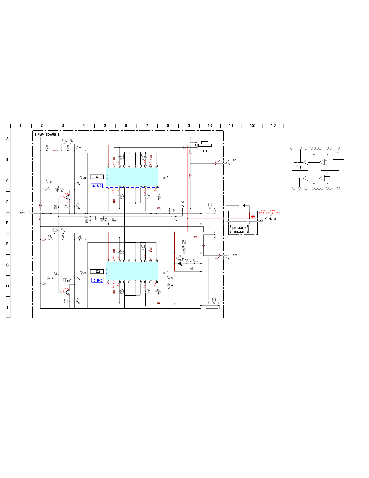
AMP
NOTE:
•Due to standardization, replacements in the
parts list may be different from the parts
specified in the diagrams or the components
used on the set.
•-XX and -X mean standardized parts, so they
may have some difference from the original
one.
•RESISTORS
All resistors are in ohms.
METAL: Metal-film resistor.
METAL OXIDE: Metal oxide-film resistor.
F: nonflammable
•CAPACITORS
uF: µF
•COILS
uH: µH
•Items marked “*” are not stocked since they
are seldom required for routine service.
Some delay should be anticipated when
ordering these items.
•SEMICONDUCTORS
In each case, u: µ, for example:
uA. . : µA. . uPA. . : µPA. .
uPB. . : µPB. . uPC. . : µPC. .
uPD. . : µPD. .
•Accessories are given in the last of this parts
list.
When indicating parts by reference number,
please include the board name.
Ref. No. Part No. Description Remark Ref. No. Part No. Description Remark
*A-4542-657-A AMP BOARD, COMPLETE
********************
< CAPACITOR >
C1 1-115-467-11 CERAMIC CHIP 0.22uF 10% 10V
C2 1-115-467-11 CERAMIC CHIP 0.22uF 10% 10V
C3 1-126-188-11 ELECT CHIP 0.15uF 20% 50V
C4 1-126-188-11 ELECT CHIP 0.15uF 20% 50V
C5 1-128-397-21 ELECT CHIP 100uF 20% 16V
C6 1-128-397-21 ELECT CHIP 100uF 20% 16V
C7 1-126-209-11 ELECT CHIP 100uF 20% 4V
C8 1-126-209-11 ELECT CHIP 100uF 20% 4V
C9 1-128-397-21 ELECT CHIP 100uF 20% 16V
C10 1-128-397-21 ELECT CHIP 100uF 20% 16V
C11 1-126-209-11 ELECT CHIP 100uF 20% 4V
C12 1-126-209-11 ELECT CHIP 100uF 20% 4V
C13 1-128-397-21 ELECT CHIP 100uF 20% 16V
C14 1-128-397-21 ELECT CHIP 100uF 20% 16V
C15 1-126-393-11 ELECT CHIP 33uF 20% 10V
C16 1-124-779-00 ELECT CHIP 10uF 20% 16V
C17 1-124-779-00 ELECT CHIP 10uF 20% 16V
C18 1-125-837-91 CERAMIC CHIP 1uF 10% 6.3V
C19 1-125-837-91 CERAMIC CHIP 1uF 10% 6.3V
C20 1-125-837-91 CERAMIC CHIP 1uF 10% 6.3V
C21 1-125-837-91 CERAMIC CHIP 1uF 10% 6.3V
C22 1-126-935-11 ELECT 470uF 20% 16V
C23 1-107-726-91 CERAMIC CHIP 0.01uF 10% 16V
C24 1-165-176-11 CERAMIC CHIP 0.047uF 10% 16V
C25 1-165-176-11 CERAMIC CHIP 0.047uF 10% 16V
C26 1-162-964-11 CERAMIC CHIP 0.001uF 10% 50V
C101 1-162-964-11 CERAMIC CHIP 0.001uF 10% 50V
C102 1-162-964-11 CERAMIC CHIP 0.001uF 10% 50V
C103 1-162-964-11 CERAMIC CHIP 0.001uF 10% 50V
C104 1-162-964-11 CERAMIC CHIP 0.001uF 10% 50V
< DIODE >
D1 8-719-800-76 DIODE 1SS226
D2 8-719-812-43 DIODE TLG124A
D3 8-719-105-57 DIODE RD3.9M-B1
< IC >
IC1 8-759-524-84 IC TEA2025D-013TR
IC2 8-759-524-84 IC TEA2025D-013TR
< TRANSISTOR >
Q1 8-729-230-49 TRANSISTOR 2SC2712-YG
Q2 8-729-230-49 TRANSISTOR 2SC2712-YG
< RESISTOR >
R1 1-216-829-11 METAL CHIP 4.7K 5% 1/10W
R2 1-216-829-11 METAL CHIP 4.7K 5% 1/10W
R3 1-216-814-11 METAL CHIP 270 5% 1/10W
R4 1-216-814-11 METAL CHIP 270 5% 1/10W
R5 1-216-821-11 METAL CHIP 1K 5% 1/10W
R6 1-216-821-11 METAL CHIP 1K 5% 1/10W
R7 1-216-823-11 METAL CHIP 1.5K 5% 1/10W
R8 1-216-823-11 METAL CHIP 1.5K 5% 1/10W
R9 1-216-813-11 METAL CHIP 220 5% 1/10W
R10 1-216-813-11 METAL CHIP 220 5% 1/10W
R11 1-216-833-11 METAL CHIP 10K 5% 1/10W
R12 1-216-833-11 METAL CHIP 10K 5% 1/10W
R14 1-216-821-11 METAL CHIP 1K 5% 1/10W
R15 1-216-821-11 METAL CHIP 1K 5% 1/10W
R16 1-216-821-11 METAL CHIP 1K 5% 1/10W
R17 1-216-789-11 METAL CHIP 2.2 5% 1/10W
R18 1-216-789-11 METAL CHIP 2.2 5% 1/10W
R19 1-216-823-11 METAL CHIP 1.5K 5% 1/10W
R20 1-216-823-11 METAL CHIP 1.5K 5% 1/10W
< SWITCH >
S1 1-554-896-21 SWITCH, SLIDE (POWER)
************************************************************
JACK BOARD
***********
< JACK >
JK1 1-568-907-21 JACK, DC (POLARITY UNIFIED TYPE)
(DC IN 6V !)
************************************************************
MISCELLANEOUS
***************
17 1-824-827-31 CORD (WITH PLUG)
SP1 1-825-339-12 SPEAKER (034F003)
SP2 1-825-339-12 SPEAKER (034F003)
************************************************************
ACCESSORIES
************
3-261-127-11 MANUAL, INSTRUCTION
(ENGLISH, FRENCH, SPANISH)
JACK

9
SRS-T57
MEMO

SRS-T57
REVISION HISTORY
Clicking the version allows you to jump to the revised page.
Also, clicking the version at the upper right on the revised page allows you to jump to the next revised
page.
Ver. Date Description of Revision
1.0 2004.04 New
Other manuals for SRS-T57
1
Table of contents
Other Sony Speakers System manuals

Sony
Sony PlasmaPro PFM 42V1 User manual

Sony
Sony SS-CN495H Primary User manual

Sony
Sony SS-CN295 User manual

Sony
Sony SS-GN880 User manual

Sony
Sony HT-A3000 Reference guide

Sony
Sony SS-MF600H Instruction Manual

Sony
Sony SRS-PC45 User manual

Sony
Sony SRS-D5100 User manual

Sony
Sony AVD-LA2500PKG User manual

Sony
Sony SS-GN800 User manual