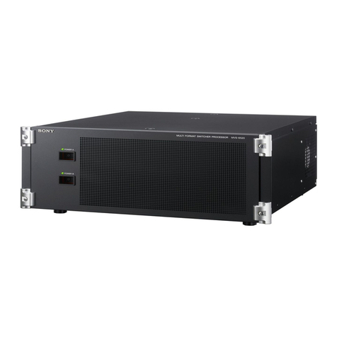
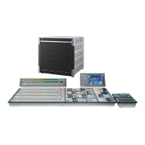
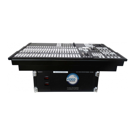
Sony MVS-6000 User manual

MVS-6000 System
(With CCP-9000 Series Center Control Panel)
User’s Guide
Multi Format Switcher System
Volume 3 [English]
1st Edition
Software Version 8.00 and Later

NOTICE TO USERS
© 2009 Sony Corporation. All rights reserved. This
manual or the software described herein, in whole or in
part, may not be reproduced, translated or reduced to
any machine readable form without prior written approval
from Sony Corporation.
SONY CORPORATION PROVIDES NO WARRANTY
WITH REGARD TO THIS MANUAL, THE SOFTWARE
OR OTHER INFORMATION CONTAINED HEREIN AND
HEREBY EXPRESSLY DISCLAIMS ANY IMPLIED
WARRANTIES OF MERCHANTABILITY OR FITNESS
FOR ANY PARTICULAR PURPOSE WITH REGARD TO
THIS MANUAL, THE SOFTWARE OR SUCH OTHER
INFORMATION. IN NO EVENT SHALL SONY
CORPORATION BE LIABLE FOR ANY INCIDENTAL,
CONSEQUENTIAL OR SPECIAL DAMAGES,
WHETHER BASED ON TORT, CONTRACT, OR
OTHERWISE, ARISING OUT OF OR IN CONNECTION
WITH THIS MANUAL, THE SOFTWARE OR OTHER
INFORMATION CONTAINED HEREIN OR THE USE
THEREOF.
Sony Corporation reserves the right to make any
modification to this manual or the information contained
herein at any time without notice.
The software described herein may also be governed by
the terms of a separate user license agreement.

3
<Organization of This User's Guide>
The User’s Guide for this system comprises Volumes 1 to 3.
Volume 1
The volume comprises the following chapters.
Chapter 1 MVS-6000 Functions
Chapter 2 Menus and Control Panel
Chapter 3 Signal Selection and Transitions
Chapter 4 Keys
Chapter 5 Wipes
Chapter 6 DME Wipes
Chapter 7 Frame Memory
Chapter 8 Color Backgrounds, Copy and Swap, and Other Settings
Chapter 9 Color Corrector
Chapter 10 Special Functions
Appendix (Volume 1)
• Wipe Pattern List
• DME Wipe Pattern List
• Resizer DME Wipe Pattern List
• Menu Tree
Index
Volume 2
The volume comprises the following chapters.
Chapter 11 DME Operations
Chapter 12 External Devices
Chapter 13 Keyframe Effects
Chapter 14 Snapshots
Chapter 15 Utility/Shotbox
Chapter 16 Macros
Chapter 17 Files
Appendix (Volume 2)
• SpotLighting
• Functional Differences With Models of DME
• Macro File Editing Rules
• About the Macro Attachment List Display
• Menu Operations Not Recorded in a Menu Macro
Index
Volume 3
This book. For the contents of this volume, see “Table of Contents” at the front.
Chapter 18 System Setup (System)
Chapter 19 Control Panel Setup (Panel)
Chapter 20 Switcher Setup (Switcher)
Chapter 21 DME Setup (DME)
Chapter 22 DCU Setup (DCU)

4
Chapter 23 Setup Relating to Router Interface and Tally (Router/Tally)
Chapter 24 Simple Connection of the MKS-8080/8082 AUX Bus Remote
Panel
Chapter 25 DIAGNOSIS
Appendix (Volume 3)
• Data Saved by [Setup Define] and [Initial Status Define]
• Error Messages
Index

5Table of Contents
Table of Contents
Chapter 18 System Setup (System)
Setup for the Whole System.........................................................................13
Network Settings (Network Config Menu).................................................14
Making the Network Settings................................................................14
System Settings (System Config Menu)......................................................15
Specifying the Switcher Controlled by the Control Panel ....................15
Specifying the DME Connected to the Switcher...................................16
Enabling the FM Data Port of the Switcher ..........................................17
Setting the Signal Format (Format Menu).................................................18
Setting the Signal Format ......................................................................18
Switching the Input Reference Signal for HD System..........................19
Setting Conversion Formats ..................................................................20
Setting the Screen Aspect Ratio (Format Menu).......................................23
Selecting the State After Powering On (Start Up Menu)..........................24
Saving and Recalling Setup Data ..........................................................25
Selecting the State at Start-up ...............................................................26
Saving User-Defined Settings ...............................................................27
Setting Automatic Loading of Register Data at Power On (Autoload
Function) ....................................................................................27
Reset and Initialization (Initialize Menu)...................................................29
Installation and Device Setup (Install/Unit Config Menu) .......................30
Installing Software ................................................................................30
Making Settings Required to Use the Software ....................................32
Adding User Texture Patterns ...............................................................35
Saving a Frame Memory Clip With Ancillary Data..............................42
System Maintenance (Maintenance Menu)................................................43
Setting the Date and Time .....................................................................43
Using a Memory Card ...........................................................................44
Carrying Out the Primary Setting..........................................................44
Reloading a USB Driver........................................................................45
Initializing the Hard Disk ......................................................................45
Locking the Setup Menu Settings .........................................................46

6Table of Contents
Chapter 19 Control Panel Setup (Panel)
Overall Control Panel Settings (Config Menu)..........................................54
Panel Setup ............................................................................................54
Interchanging the Bank Order or Disabling Operation .........................55
Assigning Two M/E Banks to One M/E Bank ......................................56
Assigning the Key Delegation in the Downstream Key Control Block
(MKS-8032 DSK Fader Module, Option) .................................57
Linking Switcher Bus and Router Destination......................................58
Linking Transitions Between Keyers ....................................................61
Linking the Next Transition Selection Buttons.....................................61
Selecting the Module to be the Reference for Device Control Block ...62
Assigning a Region to a Region Selection Button in the Numeric Keypad
Control Block.............................................................................62
Setting the Assignment of Transition Type Selection Buttons .............64
Setting VTR Operation Button Assignment..........................................65
Setting the Assignment of Macro Operation Buttons ...........................67
Assigning Keys to the DSK1 and DSK2 Buttons in the Downstream Key/
Fade-to-Black Control Block .....................................................67
Assigning Keys to the Independent Key Transition Control Block
(Simple Type) ............................................................................68
Assigning Preview Output to Preview Selection Buttons .....................70
Assigning Functions to the Device Control Block................................71
Inhibiting Utility Bus and Key Operations............................................73
Assigning Functions to the Menu Control Block Top Menu and User
Preference Buttons .....................................................................74
Cross-Point Settings (Xpt Assign Menu)....................................................75
Creating Cross-Point Assign Tables......................................................76
Copying Cross-Point Assign Tables......................................................81
Selecting Cross-Point Assign Tables ....................................................82
Exporting Source Names and Destination Names.................................83
Making Settings for Audio Mixer .........................................................84
Assigning a Cross-Point Button to Enable/Disable Side Flags.............85
Auxiliary Bus Control Block Settings (Aux Assign Menu).......................87
Assigning a Bus to an AUX Delegation Button....................................87
Using the Auxiliary Bus Control Block for Router Control .................88
Setting Button Assignments (Prefs/Utility Menu) .....................................93
Assigning Functions to User Preference Buttons..................................93
Assigning a Function to a Memory Recall Button in the Utility/Shotbox
Control Block (MKS-8033 Utility/Shotbox Module, Option)...98

7Table of Contents
Interfacing With External Devices (Device Interface Menu) .................104
Making Control Panel GPI Input Settings...........................................104
Making Control Panel GPI Output Settings ........................................107
Setting the Control Mode for P-Bus Devices......................................109
Setting the SCU Editor Panel Port ......................................................109
Making DCU Serial Port Settings .......................................................110
Sharing Disk Recorder/Extended VTR File Lists ...............................111
Operation Settings (Operation Menu)......................................................112
Setting the On-Air Tally......................................................................113
Setting the Transition Rate Display Mode ..........................................113
Making Settings Relating to Effects....................................................113
Setting the First Keyframe When a Rewind is Executed ....................114
Setting the Source and Destination Names .........................................114
Settings for the Wipe Snapshot Menu .................................................115
Setting the Button Operation Mode.....................................................116
Setting Trackball, Joystick, Search Dial, and Double-Click Sensitivity
..................................................................................................117
Specifying Main Split Fader................................................................118
Setting the Macro Execution Mode.....................................................118
Screen Saver and Other Settings (Maintenance Menu)..........................120
Screen Saver Settings ..........................................................................120
Adjusting the Brightness .....................................................................120
Adjusting the Alarms...........................................................................121
Calibrating the Touch Panel ................................................................121
Setting the Menu to be Shown When the Menus Are Started.............122
Selecting the Mouse Button Used for Adjusting the Knob Parameters
..................................................................................................122
Chapter 20 Switcher Setup (Switcher)
Settings for Switcher Configuration (Config Menu)...............................125
Adjusting the Reference Phase............................................................126
Specifying the Video Switching Timing .............................................126
Setting the Operation Mode ................................................................126
Setting User Regions ...........................................................................128
Assigning PGM/PST Logically to an M/E..........................................129
Setting the Assignments of DME Channels to Use on the Individual M/E
Banks........................................................................................129
Setting the Side Flag Video Material and Operation ..........................130
Signal Input Settings (Input Menu) ..........................................................132
8Table of Contents
Making Phase Adjustment and Through Mode Settings.....................132
Making Video Process Settings...........................................................133
Enabling the Illegal Color Limiter ......................................................133
Setting the Format Converter Inputs ...................................................134
Signal Output Settings (Output Menu) ....................................................140
Assigning Output Signals ....................................................................140
Setting the Output Signal ....................................................................141
Settings Relating to Video Switching (Transition Menu) .......................145
Selecting the Bank to Make the Settings.............................................145
Settings Relating to Keys, Wipes, Frame Memory and Color Correction
(Key/Wipe/FM/CCR Menu)...........................................................148
Switching Video Process Memory On or Off .....................................148
Settings for the Show Key Function....................................................149
Settings for Key Auto Drop Function .................................................149
Automatically Naming and Saving to Frame Memory .......................150
Selecting the Bank to Make the Settings.............................................150
Settings Relating to Function Links (Link Menu)...................................153
Setting a Cross-Point Button Link.......................................................153
Making Link Table Settings ................................................................155
Linking Cross-Point Buttons and GPI Output Ports ...........................155
Making a Setting for Linking Two M/E Banks...................................157
Making a Link Setting for Key Transition ..........................................158
Interfacing With External Devices (Device Interface Menu) .................160
Making 9-Pin Port Device Interface Settings......................................160
Making Switcher Processor GPI Input Settings ..................................161
Making Switcher Processor GPI Output Settings ...............................164
Enabling or Disabling AUX Bus Control............................................166
Setting the Interface Between the DME and the Switcher..................166
Selecting the Mode for Turning Off Keys Upon Receiving the Editor
Command .................................................................................168
Chapter 21 DME Setup (DME)
Settings Relating to Signal Inputs (Input Menu).....................................170
Setting the Initial Crop ........................................................................170
Setting an Illegal Color Limit for Matte Signals.................................171
Making DME System Phase Adjustment............................................171
Setting the TBC Window Center Position ..........................................171
Settings Relating to Signal Outputs (Output Menu) ...............................173
Adjusting the Monitor Output .............................................................173

9Table of Contents
Setting the Monitor Output..................................................................174
Interfacing With External Devices (Device Interface Menu) .................175
Making DME GPI Input Settings ........................................................176
Making DME GPI Output Settings .....................................................178
Chapter 22 DCU Setup (DCU)
Setup Relating to DCU...............................................................................180
Settings Relating to Parallel Inputs (Input Config Menu)......................181
Assigning a GPI Input Port .................................................................181
Releasing the Assignment of a GPI Input Port....................................182
GPI Input Setting (GPI Input Assign Menu)...........................................183
Making DCU GPI Input Settings ........................................................183
Parallel Output Settings (Output Config Menu) .....................................187
Assigning a GPI Output Port...............................................................187
Releasing the Assignment of a GPI Output Port.................................188
GPI Output Setting (GPI Output Assign Menu) .....................................189
Making DCU GPI Output Settings......................................................189
Serial Port Settings (Serial Port Assign Menu) .......................................192
Making Serial Port Settings.................................................................192
Making Detailed Settings on the External Device Connected to the Serial
Port ...........................................................................................194
Chapter 23 Setup Relating to Router Interface and Tally (Router/Tally)
Router Interface Settings (Router Menu) ................................................204
Assigning Switcher Inputs and Outputs to S-Bus Space.....................204
Making an External Box Setting .........................................................205
Tally Group Settings (Group Tally Menu) ..............................................208
Wiring Settings (Wiring Menu) ................................................................209
Making New Wiring Settings..............................................................209
Changing the Wiring Settings .............................................................210
Deleting Wiring Settings .....................................................................210
Sorting Wiring Settings .......................................................................210
Tally Generation Settings (Tally Enable Menu)......................................212
Making New Tally Generation Settings ..............................................212
Modifying Tally Generation................................................................213
Deleting Tally Generation Settings .....................................................213
Tally Copy Settings (Tally Copy Menu)...................................................215
Making New Tally Copy Settings .......................................................215
Modifying Tally Copy Settings...........................................................216

10 Table of Contents
Deleting Tally Copy Settings ..............................................................216
Parallel Tally Settings (Parallel Tally Menu) ..........................................217
Making or Modifying Parallel Tally Settings......................................217
Deleting Parallel Tally Settings...........................................................218
Serial Tally Settings (Serial Tally Menu) .................................................219
Setting or Changing the Serial Tally Settings .....................................219
Making the Serial Tally Source Address Settings...............................219
Clearing a Source Address Setting ......................................................220
Chapter 24 Simple Connection of the MKS-8080/8082 AUX Bus Remote Panel
Procedure for Simple Connection.............................................................222
Setting Status of the MKS-8080/8082 in Simple Connection..................224
Chapter 25 DIAGNOSIS
Checking the Communications Status......................................................226
Communications Status Display .........................................................226
Appendix (Volume 3)
Data Saved by [Setup Define] and [Initial Status Define].......................230
Data Saved by [Setup Define] .............................................................231
Data Saved by [Initial Status Define]..................................................236
Error Messages ...........................................................................................239
Error Messages Displayed in the Error Status/Error Log Menu .........239
Error Messages Appearing in a Message Box.....................................244
Error Messages Shown in the Error Information Menu ......................256
Index ...........................................................................................................258

Chapter 18 System Setup (System)
Setup for the Whole System .......................................................................13
Network Settings (Network Config Menu) ...............................................14
Making the Network Settings ..............................................................14
System Settings (System Config Menu) ....................................................15
Specifying the Switcher Controlled by the Control Panel ..................15
Specifying the DME Connected to the Switcher .................................16
Enabling the FM Data Port of the Switcher ........................................17
Setting the Signal Format (Format Menu) ...............................................18
Setting the Signal Format ....................................................................18
Switching the Input Reference Signal for HD System ........................19
Setting Conversion Formats ................................................................20
Setting the Screen Aspect Ratio (Format Menu) .....................................23
Selecting the State After Powering On (Start Up Menu) ........................24
Saving and Recalling Setup Data ........................................................25
Selecting the State at Start-up .............................................................26
Saving User-Defined Settings .............................................................27
Setting Automatic Loading of Register Data at Power On (Autoload
Function) ..................................................................................27
Reset and Initialization (Initialize Menu) .................................................29
Installation and Device Setup (Install/Unit Config Menu) .....................30
Installing Software ..............................................................................30
Making Settings Required to Use the Software ..................................32
Adding User Texture Patterns .............................................................35
Saving a Frame Memory Clip With Ancillary Data ............................42
System Maintenance (Maintenance Menu) ..............................................43
Setting the Date and Time ...................................................................43
Using a Memory Card .........................................................................44
Carrying Out the Primary Setting ........................................................44
Reloading a USB Driver ......................................................................45
Initializing the Hard Disk ....................................................................45

13Setup for the Whole System
Chapter 18 System Setup (System)
Setup for the Whole System
Carry out operations relating to setup for the whole system in the Engineering
Setup menu.
To access the Engineering Setup menu, press the top menu selection button
[ENG SETUP].
Here the “whole system” refers to all devices connected on the Control LAN.
The DCU is connected through the control panel, but is also included in the
“whole system.”
For an overview of setup, see “Setup” in Chapter 1 (Volume 1).
Setting the unit ID
When there are two switchers and connected DME units on the same network,
it is necessary to set the unit ID on each device, as follows.
For more details of how to make the unit ID settings, refer to the installation
manual for the particular device.
Switcher ID
Switcher 1
DME ID
DME1 1
DME2 2

Chapter 18 System Setup (System)
14 Network Settings (Network Config Menu)
Network Settings (Network Config Menu)
This provides automatic configuration of all devices connected to the Data
LAN (excluding the DCU), and displays a list of them.
To make the network settings, use System >Network Config menu.
To display the Network Config menu
In the Engineering Setup menu, select VF1 ‘System’ and HF1 ‘Network
Config.’
The status area shows the device ID, and Control LAN and Data LAN IP
addresses for each device excluding the DCU.
Making the Network Settings
1
In the System >Network Config menu, press [Auto Config].
This automatically checks all devices (excluding the DCU) connected to
the Data LAN.
2
Once switch to another menu, then display the Network Config menu
again.
Now the status area of the System >Network Config menu shows the
results of the automatic check.
Note
Be sure to carry out this operation after reconfiguring the system, or after a
software upgrade.

15System Settings (System Config Menu)
Chapter 18 System Setup (System)
System Settings (System Config Menu)
Specify the overall system operation mode and the hierarchical relationship of
the devices.
To make the system settings, use the System >System Config menu.
To display the System Config menu
In the Engineering Setup menu, select VF1 ‘System’ and HF2 ‘System
Config.’
Note
After changing any of the following settings, be sure to press [Execute] to save
the new values. If you want to cancel the setting changes without saving them,
press [Clear].
Specifying the Switcher Controlled by the Control Panel
1
In the System >System Config menu, press the [Panel Assign] button.
The Panel Assign menu appears.
2
Select the switcher to be controlled by the selected control panel, as
follows.
•If there is only one switcher on the network, in the <1st Switcher>
group, set [SWR1] to On, and in the <2nd Switcher> group, set [SWR2]
to Off.
•If there are two switchers on the same network, in the <1st Switcher>
group, select the switcher to be operated.
3
To set the selected control panel as tally control master panel, press [Tally
Master], turning it on.
If there are multiple panels and processors, the control panel for which
[Tally Master] is set to On carries out tally control for the whole system.
Note
When there are multiple control panels, make sure that one of them has
[Tally Master] set to On. When you change the master panel, be sure to
copy and save the setup tally (TLY) and router (RTR) data in the File
menu, and make the same settings for other panels.

Chapter 18 System Setup (System)
16 System Settings (System Config Menu)
To select the lighting mode of the switcher bus selection buttons
on the remote panel
When switching buses with the MKS-8080/8082 AUX Bus Remote Panel or
other remote panel connected via S-Bus data link, you can select the lighting
mode of the bus selection buttons.
In the System >System Config >Panel Assign menu, select either of the
following in the <S-Bus Remote Sw'er Status> group.
Mode 1: The inhibited buttons do not light even when pressed, and the other
buttons light after a longer delay time than in Mode 2.
Mode 2: The delay time for button lighting is reduced, but even the inhibited
buttons may light for a moment when pressed.
Notes
• Make sure that [Tally Master] is set to On.
• When simple connection is used between the center control panel and remote
panel, this setting is disabled.
Specifying the DME Connected to the Switcher
1
In the System >System Config menu, press [Switcher Assign].
The Switcher Assign menu appears.
2
Using either of the following methods, select the switcher to which the
settings apply.
• In the list appearing in the menu, press the desired device name.
• Press the arrow keys to scroll the reverse video cursor.
The selected switcher appears in reverse video.
If there is only one switcher on the network, carry out the SWR1 setting
(for the first switcher) only.
3
Make the DME settings as follows.
•When making DME settings for SWR1 (the first switcher), for the
first DME, select [DME1] in the <1st DME> group.Turn all buttons in
the <2nd DME> group off.
•When making DME settings for SWR2 (the second switcher), for the
first DME, select [DME3] in the <1st DME> group. Turn all buttons in
the <2nd DME> group off.

17System Settings (System Config Menu)
Chapter 18 System Setup (System)
Enabling the FM Data Port of the Switcher
With the FM data port enabled, frame memory data can be transferred in a short
time between the switcher and the control panels.
Note
If multiple control panels are in use, [FM Data Port Enbl] can be turned on for
only one control panel per switcher.
1
In the System >System Config menu, press [Switcher Assign].
The Switcher Assign menu appears.
2
Using any of the following methods, select the switcher to be set.
• Press directly on the list in the status area.
• Press the arrow keys to scroll the reverse video cursor.
The selected switcher is displayed in reverse video.
If there is only one switcher on the network, make the setting only for
SWR1 (the first switcher).
3
Press [FM Data Port Enbl], turning it on.

Chapter 18 System Setup (System)
18 Setting the Signal Format (Format Menu)
Setting the Signal Format (Format Menu)
To set the format, that is, the frame frequency and number of scan lines handled
by each device, use the System >Format menu.
To display the Format menu
In the Engineering Setup menu, select VF1 ‘System’ and HF3 ‘Format.’
Note
After changing any of the following settings, be sure to press [Execute] (or [FC
Format Execute] for changing the format converter signal format) to save the
new values. If you want to cancel the settings and return to the original state,
press [Clear] without pressing [Execute] or [FC Format Execute]. When you
press [Execute], some data is lost (such as frame memory images). If you press
[FC Format Execute], memory is not initialized, and this data is not lost.
Setting the Signal Format
Specify the signal format to be handled by the devices.
The combinations of signal formats that can be selected are as follows.
To use the MVS-6000 with multi-format support requires the optional BZS-
6540M Switcher Upgrade Software.
The following software options are also required depending on the number of
M/E banks.
To use the software, you are required to input an install key.
System Field frequency Effective number of scan lines
HD system 50 1080i
59.94
50 720P
59.94
SD system 59.94 480i
50 576i
Product name Model No. System
Mix/Effect Upgrade Software BZS-6550M 2M/E system
Additional M/E Software BZS-6300 2M/E system

19Setting the Signal Format (Format Menu)
Chapter 18 System Setup (System)
For the method of inputting an install key, see “Making Settings Required to
Use the Software” (page 32).
1
In the System >Format menu, select the device for operations.
• Press directly on the list in the status area.
• Press the arrow keys to scroll the reverse video cursor.
• Turn the knob.
2
Press [Signal Format].
A pop-up window appears.
3
Press the button for the desired signal format.
Switching the Input Reference Signal for HD System
This changes the input reference signal.
•Tri Sync: tri-level sync for an HD system
•BB (Black Burst): black burst or sync for an SD system
The following table shows the relation between signal format and the
frequency of a signal that can be used as the input reference signal.
Knob Parameter Adjustment Setting values
1 Device Selection of device for operations 1 and upwards
Signal format Input reference signal
Tri Sync Black burst
1080i/59.94 59.94 Black Burst 59.94 Sync 59.94
1080i/50 50 Black Burst 50 Sync 50
720P/59.94 59.94 Black Burst 59.94 Sync 59.94
720P/50 – Black Burst 50 Sync 50

Chapter 18 System Setup (System)
20 Setting the Signal Format (Format Menu)
Setting Conversion Formats
Installing the MKS-8450G Format Converter Board in the MVS-6000 enables
signal video format conversions.
This operation is valid only when BB is selected in the <Ref Input Format>
group.
Format converter
Installing the MKS-8450G Format Converter Board in the switcher enables the
following signal video format conversions.
• Up-conversion: from SD (4:3) to HD (16:9)
• Down-conversion: from HD (16:9) to SD (4:3)
• Cross-conversion: from HD (720P) to HD (1080i), or from HD (1080i) to
HD (720P)
The maximum number of input signals for which format conversion is possible
is 8, and the maximum number of output signals is 2.
Notes
• After format conversion, input and output signals have one-frame delays
with respect to the reference signals.
• It is not possible to apply the safe title function to output signals subjected to
format conversion.
• When the input reference signal for HD system is set to Tri Sync, the format
converter function is not available.
For details, see “Switching the Input Reference Signal for HD System”
(page 19)
Other manuals for MVS-6000
2
Table of contents
Other Sony Switch manuals

Sony
Sony DVS-7200 User manual

Sony
Sony DMX-SW1 - Bravia Input Link User manual

Sony
Sony XVS-G1 User manual

Sony
Sony DVS-7000 User manual

Sony
Sony HKS-5810M User manual

Sony
Sony CAV-CVS12ES - Component Video Switcher User manual

Sony
Sony DVS-7000A User manual

Sony
Sony MVS-8000X SystemMVS-7000X System User manual

Sony
Sony SB-V60S - Auto Switcher AV Selector User manual

Sony
Sony MVS-8000G-C Quick start guide