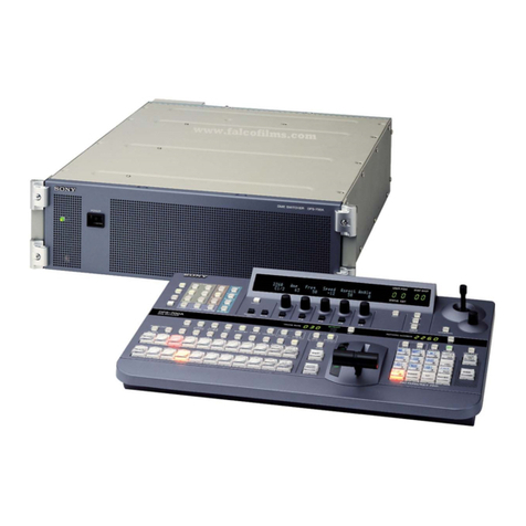
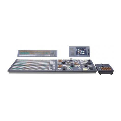
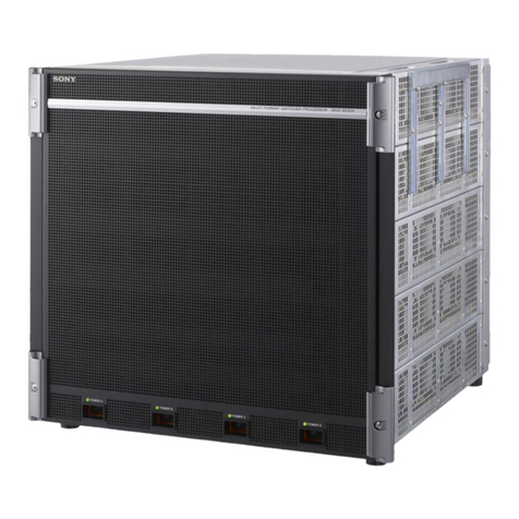
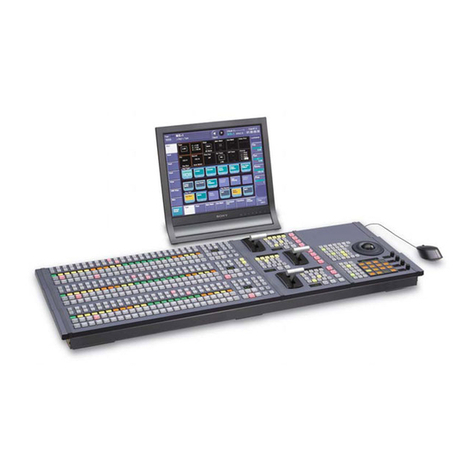
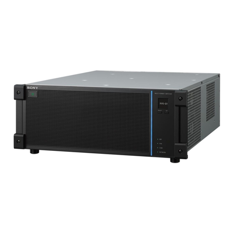
Sony DVS-7200A User manual

MAINTENANCE MANUAL Part 1
1st Edition (Revised 1)
DVS-7200A
SWITCHER CONTROL PANEL
BKDS-7015
DIGITAL VIDEO SWITCHER
BKDS-7025/7026
BKDS-2031
BKDS-2032
BKDS-2041
BKDS-2070
BKDS-7001
BKDS-7002
BKDS-7030
BKDS-7031
BKDS-7033
BKDS-7075
BKDS-7090
BKDS-7091
BKDS-7103
BKDS-7110
BKDS-7111
BKDS-7113
BKDS-7133
BKDS-7161
BKDS-7163
BKDS-7250
BKDS-7270
BKDS-7271
BKDS-7280
BKDS-7340
BKDS-7370
BKDS-7420
BKDS-7444
BKDS-7445
BKDS-7690
BZS-7040A
BZS-7060A

!WARNING
This manual is intended for qualified service personnel only.
To reduce the risk of electric shock, fire or injury, do not perform any servicing other than that
contained in the operating instructions unless you are qualified to do so.Refer all servicing to
qualified service personnel.
!WARNUNG
Die Anleitung ist nur für qualifiziertes Fachpersonal bestimmt.
Alle Wartungsarbeiten dürfen nur von qualifiziertem Fachpersonal ausgeführt werden. Um die
Gefahr eines elektrischen Schlages, Feuergefahr und Verletzungen zu vermeiden, sind bei
Wartungsarbeiten strikt die Angaben in der Anleitung zu befolgen. Andere als die angegeben
Wartungsarbeiten dürfen nur von Personen ausgeführt werden, die eine spezielle Befähigung
dazu besitzen.
!AVERTISSEMENT
Ce manual est destiné uniquement aux personnes compétentes en charge de l’entretien.Afin
de réduire les risques de décharge électrique, d’incendie ou de blessure n’effectuer que les
réparations indiquées dans le mode d’emploi à moins d’être qualifié pour en effectuer d’autres.
Pour toute réparation faire appel à une personne compétente uniquement.
DVS-7200A Serial No. 10001 and Higher
BKDS-2031 Serial No. 10001 and Higher
BKDS-2032 Serial No. 10001 and Higher
BKDS-2041 Serial No. 10001 and Higher
BKDS-2070 Serial No. 10001 and Higher
BKDS-7001 Serial No. 10001 and Higher
BKDS-7002 Serial No. 10001 and Higher
BKDS-7015 Serial No. 10001 and Higher
BKDS-7025 Serial No. 10001 and Higher
BKDS-7026 Serial No. 10001 and Higher
BKDS-7030 Serial No. 10001 and Higher
BKDS-7031 Serial No. 10001 and Higher
BKDS-7033 Serial No. 10001 and Higher
BKDS-7075 Serial No. 10001 and Higher
BKDS-7090 Serial No. 10001 and Higher
BKDS-7091 Serial No. 10001 and Higher
BKDS-7103 Serial No. 10001 and Higher
BKDS-7110 Serial No. 10001 and Higher
BKDS-7111 Serial No. 10001 and Higher
BKDS-7113 Serial No. 10001 and Higher
BKDS-7133 Serial No. 10001 and Higher
BKDS-7161 Serial No. 10001 and Higher
BKDS-7163 Serial No. 10001 and Higher
BKDS-7250 Serial No. 10001 and Higher
BKDS-7270 Serial No. 10001 and Higher
BKDS-7271 Serial No. 10001 and Higher
BKDS-7280 Serial No. 10001 and Higher
BKDS-7340 Serial No. 10001 and Higher
BKDS-7370 Serial No. 10001 and Higher
BKDS-7420 Serial No. 10001 and Higher
BKDS-7444 Serial No. 10001 and Higher
BKDS-7445 Serial No. 10001 and Higher
BKDS-7690 Serial No. 10001 and Higher
BZS-7040A Serial No. 10001 and Higher
BZS-7060A Serial No. 10001 and Higher

WARNING
This unit has no power switch.
When installing the unit, incorporate a readily
accessible disconnect device in the fixed wiring, or
connect the power cord to a socket-outlet which must be
provided near the unit and easily accessible, so that the
user can turn off the power in case a fault should occur.
WARNUNG
Dieses Gerät hat keinen Netzschalter.
Beim Einbau des Geräts ist daher im Festkabel ein leicht
zugänglicher Unterbrecher einzufügen, oder das
Netzkabel mu
ß
mit einer in der Nähe des Geräts
befindlichen, leicht zugänglichen Wandsteckdose
verbunden werden, damit sich bei einer
Funktionsstörung die Stromversorgung zum Gerät
jederzeit unterbrechen lä
ß
t.
Attention-when the product is installed in Rack:
1. Prevention against overloading of branch circuit
When this product is installed in a rack and is
supplied power from an outlet on the rack, please
make sure that the rack does not overload the supply
circuit.
2. Providing protective earth
When this product is installed in a rack and is
supplied power from an outlet on the rack, please
confirm that the outlet is provided with a suitable
protective earth connection.
3. Internal air ambient temperature of the rack
When this product is installed in a rack, please make
sure that the internal air ambient temperature of the
rack is within the specified limit of this product.
4. Prevention against achieving hazardous
condition due to uneven mechanical loading
When this product is installed in a rack, please make
sure that the rack does not achieve hazardous
condition due to uneven mechanical loading.


1
DVS-7200AE MMP1
Table of Contents
Manual Structure
Purpose of this manual .............................................................................................. 3
Related manuals......................................................................................................... 3
Contents ..................................................................................................................... 4
1. Service Overview
1-1. DVS-7200A.................................................................................................1-1
1-1-1. Removal and Installation of Front Panel....................................1-1
1-1-2. Location of Main Parts...............................................................1-2
1-1-3. Inserting/Pulling Out of Plug-in Boards ....................................1-4
1-1-4. Capacitor for Data Backup.........................................................1-5
1-1-5. Spare Parts..................................................................................1-6
1-2. Control Panel...............................................................................................1-7
1-2-1. Opening and Closing of Panel....................................................1-7
1-2-2. Turning On/Off the Power Switch .............................................1-8
1-2-3. Removal of Exterior Parts..........................................................1-9
1-2-4. Location of Main Parts.............................................................1-10
1-2-5. Installation and Removal of Boards.........................................1-15
1-2-6. Replacement of Backup Memory IC........................................1-43
1-2-7. Spare Parts................................................................................1-44
2. Replacement of Main Parts
2-1. DVS-7200A.................................................................................................2-1
2-1-1. Replacement of Fan on the Rear Panel ......................................2-1
2-1-2. Replacement of Power Unit .......................................................2-3
2-2. Control Panel...............................................................................................2-4
2-2-1. Replacement of Rotary Encoder ................................................2-4
2-2-2. Replacement of Fader ................................................................2-7
2-2-3. Replacement of EL Display .......................................................2-8
2-2-4. Replacement of FDD (Floppy Disk Drive) Unit......................2-10
2-2-5. Replacement of Power Unit .....................................................2-12

2DVS-7200AE MMP1
3. Troubleshooting (Control Panels)
3-1. Self Diagnostics Mode (BKDS-7015) ........................................................3-1
3-2. Switch Settings on the CPU-246 Board and LEDs Description
(BKDS-7015) ..............................................................................................3-2
3-3. Troubleshooting (BKDS-7015).................................................................3-10
3-3-1. Tools and Equipment Required for Troubleshooting...............3-10
3-3-2. Connecting the Test Terminal with Connector to This Unit ....3-12
3-3-3. Starting of the Self Diagnostics Mode .....................................3-13
3-3-4. Test Procedures ........................................................................3-15
3-3-5. Ending the Self Diagnostics Mode ...........................................3-33
3-4. Self Diagnostics Mode (BKDS-7025/7026) .............................................3-34
3-5. Switch Settings on the CPU-263 Board and LEDs Description
(BKDS-7025/7026) ...................................................................................3-35
3-6. Troubleshooting (BKDS-7025/7026)........................................................3-43
3-6-1. Tools and Equipment Required for Troubleshooting...............3-43
3-6-2. Connecting the Test Terminal with Connector to This Unit ....3-45
3-6-3. Starting of the Self Diagnostics Mode .....................................3-46
3-6-4. Test Procedures ........................................................................3-48
3-6-5. Ending the Self Diagnostics Mode ...........................................3-67
4. Periodic Check and Maintenance
4-1. Cleaning ......................................................................................................4-1
4-1-1. Front Panel .................................................................................4-1
4-1-2. Fans ............................................................................................4-1
4-1-3. Track Ball (BKDS-7031) ...........................................................4-2
5. Overall Block Diagrams
5-1. DVS-7200A (2ME SYSTEM) ....................................................................5-2
DVS-7200A (2.5ME SYSTEM) .................................................................5-4
5-2. BKDS-7015 .................................................................................................5-7
5-3. BKDS-7025/7026......................................................................................5-12

3
DVS-7200AE MMP1
Manual Structure
Purpose of this manual This manual is the maintenance manual part 1 of Digital Video Switcher DVS-7200A.
This manual is intended for use by trained system and service engineers, and
describes the information for general service and periodic maintenance with the
intention of servicing including the replacement of the principal blocks and mounted
circuit boards.
Related manuals The following manuals are prepared for DVS-7200A.
The part numbers of these manuals as of February, 1999 describe.
..
..
.User’s Guide (Supplied with BZS-7040A or 7060A)
This manual describes the application and operation of DVS-7200A.
..
..
.Operation Manual (Supplied with DVS-7200A)
This manual describes the overview, system configuration examples and specifica-
tions.
..
..
.Installation Manual (Supplied with DVS-7200A)
This manual describes the information when installing DVS-7200A.
Part number : 3-201-868-01
..
..
.Maintenance Manual Part 2
The following manuals describe the detailed service information. For obtaining,
please contact your local Sony’s sale/service office.
Volume 1 (Block diagrams and Frame wirings)
Part number : 9-967-615-03
Supplement 4 Part number : 9-967-615-84
Volume 2
(Spare parts, Service overview and Replacement of main parts)
Part number : 9-967-616-03
Supplement 5 Part number : 9-967-616-85
Volume 3 (Semiconductor pin assignments)
Part number : 9-967-617-03
Supplement 3 Part number : 9-967-617-83
Volume 4 (Board layouts)
Part number : 9-967-618-03
Supplement 4 Part number : 9-967-618-84

4DVS-7200AE MMP1
..
..
.Maintenance Manual Part 2
Volume 5 (Schematic diagrams 1 A through I)
Part number : 9-967-624-03
Supplement 3 Part number : 9-967-624-83
Volume 6 (Schematic diagrams 2 K through Z)
Part number : 9-967-625-02
Supplement 4 Part number : 9-967-625-84
Contents This manual is organized by following sections.
Section 1 Service Overview
For DVS-7200A, this section describes the removal and installation of front panel,
location of main parts, inserting/pulling out of plug-in boards, capacitor for data
backup, and spare parts.
For control panel, this section describes the opening and closing of panel, removal of
exterior parts, location of main parts, installation and removal of boards, replace-
ment of backup memory IC and spare parts.
Section 2 Replacement of Main Parts
For DVS-7200A and control panel, this section describes the main parts replacement.
Section 3 Troubleshooting (Control Panels)
This section describes the self diagnostics mode of the control panels.
Section 4 Periodic Check and Maintenance
This section describes the periodic check and maintenance.
Section 5 Overall Block Diagrams
This section describes the overall block diagrams.

1-1
DVS-7200AE MMP1
Section 1
Service Overview
1-1. DVS-7200A
1-1-1. Removal and Installation of Front Panel
(1) Loosen the four locking screws on the front panel using a flatblade screwdriver.
(2) Remove the front panel in the direction of the arrow.
(3) Install the front panel in the reverse order of the procedures (1) and (2).
Front panel
Locking screws
Locking screws

1-2 DVS-7200AE MMP1
9BKDS-2041 : Frame memory board
8BKDS-7444 : Frame memory expansion board
!/ BKDS-7133 : Encoder board
!- BKDS-7133 : CRK analog component input board
!= BKDS-2031 : Chromakey board
![ BKDS-2032 : Chromakey upgrade board
@] BKDS-7161 : Analog composite output board
@\ BKDS-7163 : Serial digital output board
@[ Output processor board
@; Cross point board
@' BKDS-7103 : 12 input serial digital board
@. BKDS-7111 : Analog composite input board
#/ BKDS-7113 : Serial digital input board
@, BKDS-7110 : Blank input adaptor board
2
3 (Spare)
4 and 5
6, 8 and 10
7, 9 and 11
12 and 13
14 and 15
16, 17
and 18
2IF-758 board
3MEM-94 board
4CA-35B board
5CPU-264 board
2Interface board
3Memory board
4Application board
5System control board
6BKDS-7420 : Color correction board
7BKDS-7445 : Frame memory adaptor board
6CC-81 board
7YC-59 board
9MY-66 board
8MY-95 board
!/ ENC-34 board
!- ADC-22 board
!= CRK-10 board
![ CRK-11 board
!] Video mixer board
!\ BKDS-7250 (for BKDS-7025/7026) or
BKDS-7340 (for BKDS-7015) : Video mixer board
!] MIX-35 board
(Slot No. 7 and 9)
!' BD-26 board
(Slot No. 11 only)
!, BD-35 board
(Slot No. 11 only)
!; UP-10 board
!\ MIX-35 board
(Slot No. 11 only)
!. BD-26 board
(Slot No. 7 and 9)
@/ BD-35 board
(Slot No. 7 and 9)
@[ OUT-9 board
@] DA-94 board
@\ SD-48 board
@; XPT-16 board
@' DI-36 board
@, ADC-21 board
@. ADI-3 board
#/ DI-34 board
1
1CPU-264B board 1System control board
@- WKG-12 board
or
@= WKG-27 board
!; BKDS-7280 : ME PVW board
!. BKDS-7270 : Key border board
@/ BKDS-7271 : Fine key/key border board
!' Key border board
!, Fine key/key border board
@- BKDS-2070 : Enhanced wipe generator board
@= BKDS-7370 : Advanced wipe board
Slot No. Option Board Standard Board Function Name
1-1-2. Location of Main Parts
1. Plug-in Boards
1-1. DVS-7200A
1-1-2. Location of Main Parts

1-3
DVS-7200AE MMP1
2. Except Plug-in Boards
1-1. DVS-7200A
1-1-2. Location of Main Parts
RE-110 board
Power supply DC-DC board
RE-110 board (BKDS-7690)
Power supply DC-DC board
RE-109 board
Power supply AC-DC board
RE-109 board (BKDS-7690)
Power supply AC-DC board
LE-55 board
LED board
LE-55 board (BKDS-7690)
LED board
CN-1146A board
Connector board
CN-1145 board
Connector board
MB-618 board
Mother board
Power unit
Option
Power unit
(BKDS-7690)
Fans
Fans
Fans

1-4 DVS-7200AE MMP1
1-1-3. Inserting/Pulling Out of Plug-in Boards
c
To avoid shock hazards and/or damage to the plug-in boards, be sure to turn off the power switch before
inserting or pulling out the plug-in boards.
(1) Remove the front panel. (Refer to the section 1-1-1.)
(2) Remove the 12 screws, the two board retainers and the one board holder.
PWH4 x6
PWH4 x6
PWH4 x6
Board holder
Board retainer
Board retainer
PWH4 x6
PWH4 x6
PWH4 x6
1-1. DVS-7200A
1-1-3. Inserting/Pulling Out of Plug-in Boards

1-5
DVS-7200AE MMP1
Removal
(3) Open the eject levers of the plug-in board in the direction of the arrows 1.
(4) Pull out the plug-in board from the unit.
n
Pull out the plug-in board with an equal force for both eject levers.
Installation
(5) Insert the plug-in board along the board guide rails while opening the eject levers in the direction of
the arrows 1.
(6) Connect the plug-in board to the connector on the mother board by putting the eject levers in the
direction of the arrows 2.
(7) Install the two board retainer and the one board holder in the reverse order of the procedures (1) and
(2).
1-1-4. Capacitor for Data Backup
To store a setup data and a real-time clock, the large storage capacitor (3 Farad) is mounted on the CPU-
264B board.
To charge the large storage capacitor sufficiently, turn on the power of DVS-7200A for more than about
thirty minutes. The sufficiently charged large storage capacitor enables data to be stored for about one
week in the normal temperature.
1-1. DVS-7200A
1-1-3. Inserting/Pulling Out of Plug-in Boards
1-1-4. Capacitor for Data Backup
1
1
2
2
Eject levers
Board
MB-618 board
Board guide rail

1-6 DVS-7200AE MMP1
1-1-5. Spare Parts
This section describes the information for spare parts. In case of ordering replaceable parts such as
mounted circuit boards and major components, refer to the part numbers and descriptions that are listed in
this section.
Spare Parts
Description Part No.
Mounted Circuit Board, ADC-22 (BKDS-7133) A-8269-630-A
Mounted Circuit Board, CN-1145 A-8269-605-A
Mounted Circuit Board, CN-1146A A-8321-833-A
Mounted Circuit Board, CPU-264B A-8321-034-A
(Including with CA-35B, IF-758 and MEM-94 Boards)
Mounted Circuit Board, ENC-34 (BKDS-7133) A-8269-628-A
Mounted Circuit Board, MB-618 A-8269-604-A
Mounted Circuit Board, MIX-35 (BKDS-7250/7340) A-8269-632-A
Mounted Circuit Board, OUT-9 A-8269-612-A
Mounted Circuit Board, RE-109 A-8269-598-A
Mounted Circuit Board, RE-110 A-8269-600-A
Mounted Circuit Board, XPT-16 A-8321-301-A
Printed Circuit Board, LE-55 1-620-338-11
DC Fan Motor 1-698-080-11
BKDS-7103, DI-36 Option
BKDS-7110, ADC-21 Option
BKDS-7111, ADI-3 Option
BKDS-7113, DI-34 Option
BKDS-7161, DA-94 Option
BKDS-7163, SD-48 Option
BKDS-7270, BD-26 Option
BKDS-7271, BD-35 Option
BKDS-7280, UP-10 Option
BKDS-7370, WKG-27 Option
BKDS-7420, CC-81 Option
BKDS-7444, MY-95 Option
BKDS-7445, YC-59 Option
BKDS-2031, CRK-10 Option
BKDS-2032, CRK-11 Option
BKDS-2041, MY-66 Option
BKDS-2070, WKG-12 Option
BKDS-7690, Redundant Power Supply Unit Option
1-1. DVS-7200A
1-1-5. Spare Parts

1-7
DVS-7200AE MMP1
1-2. Control Panel
1-2-1. Opening and Closing of Panel
n
When opening and closing the panels of BKDS-7025 and 7026, tilt the display panel forward.
If not, the display panel is touched against the unit with placed at the back.
(1) Loosen the screws of the slide knobs at both sides of the panel.
(2) Move the slide knobs forward and release the locks.
(3) Push up the panel and open it.
(4) Push down the panel until the slide knobs are locked, and close it.
(5) Tighten the screws of the slide knobs at both sides of the panel.
Display panel
Slide knob
Slide knob
Control panel
Slide knob
1-2. Control Panel
1-2-1. Opening and Closing of Panel

1-8 DVS-7200AE MMP1
1-2-2. Turning On/Off the Power Switch
(1) Open the panel of the control panel. (Refer to “1-2-1. Opening and Closing of panel”.)
(2) Turn off the power switches A and B in the control panel.
Slide knobs (Right and Left)
Control panel
Power switch A
OFF
POWER SUPPLY UNIT B
POWER SUPPLY UNIT A
Power switch B
OFF
1-2. Control Panel
1-2-2. Turning On/Off the Power Switch

1-9
DVS-7200AE MMP1
1-2-3. Removal of Exterior Parts
1. Display Panel (BKDS-7025/7026)
(1) Remove the 10 screws shown in the figure.
(2) Lift up the EL case in the direction of the arrow and remove it.
2. Adaptor Box (BKDS-7075)
(1) Remove the two screws shown in the figure.
(2) Lift up the AD panel in the direction of the arrow and remove it.
BV3 x10
B3 x6 BV3 x10
BV3 x10 BV3 x10
BV3 x10
BV3 x10 BV3 x10
EL case
BV3 x10
AD Panel
B3 x5
B3 x5
1-2. Control Panel
1-2-3. Removal of Exterior Parts

1-10 DVS-7200AE MMP1
1-2-4. Location of Main Parts
BKDS-7015
1-2. Control Panel
1-2-4. Location of Main Parts
@;
@\
@]
@'
8
9
5
5
!'
!;
!'
!-
3
7!;
3
!=
!,
@/
3
!]
![
1
!\
@=
4
@-
@[
@,
@.
!.
2
0
6
1CN-1149 board
2CN-1150 board
3CN-1509 board
4CPU-246 board
5DC-92 board (BKDS-7002)
6IF-523 board (BKDS-7001)
7KY-324 board
8KY-389A board
9KY-389B board
!/ KY-390 board
!- KY-391 board
!= KY-392 board
![ KY-394 board
!] KY-395A board
!\ KY-395B board
!; LE-142 board
!' LE-144 board
!, LE-146 board
!. LE-147 board (BKDS-7002)
@/ LE-148 board (BKDS-7002)
@- LE-180 board (BKDS-7002)
@= RE-146 board
@[ RE-146 board (BKDS-7091)
@] EL display
@\ Fader
@; Fan
@' FDD (Floppy disk drive) unit
@, Power unit
@. Option Power unit (BKDS-7091)

1-11
DVS-7200AE MMP1
BKDS-7025
1-2. Control Panel
1-2-4. Location of Main Parts
1CN-1143B board
2CN-1148 board
3CPU-263 board
4IF-523 board (BKDS-7001)
5KY-318A board
6KY-319A board
7KY-320 board
8KY-321 board
9KY-323 board
!/ KY-324 board
!- KY-411 board
!= KY-331 board
![ KY-332 board
!] LE-142 board
!\ LE-143 board
!; LE-144 board
!' LE-145 board
!, LE-146 board
!. LE-147 board
@/ LE-148 board
@- LE-150 board
@= RE-112 board
@[ RE-112 board (BKDS-7090)
@] EL display
@\ Fader
@; Fan
@' FDD (Floppy disk drive) unit
@, Power unit
@. Option Power unit (BKDS-7090)
@]
@,
@;
@\
@'
@.
5
@/
!=
2
![
!.
@-
4
9
!\
!,
!/
1
6
@=
!.
@[
!]
!;
!]
!-
8
7
!'
3

1-12 DVS-7200AE MMP1
BKDS-7026
1-2. Control Panel
1-2-4. Location of Main Parts
1CN-1143B board
2CN-1148 board
3CPU-263 board
4IF-523 board (BKDS-7001)
5KY-318B board
6KY-319B board
7KY-320 board
8KY-367 board
9KY-323 board
!/ KY-324 board
!- KY-411 board
!= KY-331 board
![ KY-332 board
!] LE-142 board
!\ LE-143 board
!; LE-144 board
!' LE-145 board
!, LE-146 board
!. LE-147 board
@/ LE-148 board
@- LE-150 board
@= RE-112 board
@[ RE-112 board (BKDS-7090)
@] EL display
@\ Fader
@; Fan
@' FDD (Floppy disk drive) unit
@, Power unit
@. Option Power unit (BKDS-7090)
@]
@,
@;
@\
@'
@.
5
@/
!=
2
![
!.
@-
4
9
!\
!,
!/
1
6
@=
@[
!]
!;
!-
8
7
!'
3
!]
!\
Other manuals for DVS-7200A
3
This manual suits for next models
35
Table of contents
Other Sony Switch manuals

Sony
Sony BVS-3200CP User manual

Sony
Sony PC-3000 User manual

Sony
Sony DFS-700 User manual

Sony
Sony BKDS-7017 User manual

Sony
Sony YS-S100 User manual

Sony
Sony XA-C30 - 2 Output Selector User manual

Sony
Sony MVS-8000SF User manual

Sony
Sony DCU-8000 User manual

Sony
Sony BZPS-8001 User manual

Sony
Sony MVS-6000 User manual