manuals.online logo
Brands
  1. Home
  2. •
  3. Brands
  4. •
  5. EtherWAN
  6. •
  7. Switch
  8. •
  9. EtherWAN EX75900 Series User manual

EtherWAN EX75900 Series User manual

Copyright 2020 EtherWAN Systems, Inc. Page 1
All Rights Reserved
EX75900
03/19/2020
W70G-EX75900Q2
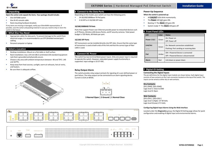
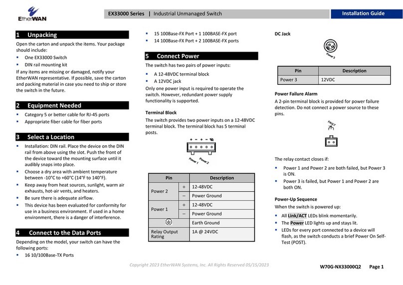
1 Unpacking
Unpack the items. Your package should include:
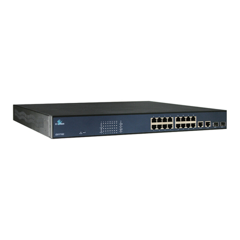
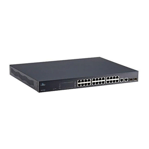
➢One EX75900 Series switch
➢On RJ-45 console cable
➢Rack-mounting hardware brackets
If items are missing or damaged, notify your EtherWAN representative.
Keep the carton and packing material.
Download the full manual at:
https://www.etherwan.com
2 What Else You Need
➢Appropriate cables for data ports. To prevent damage to the switch
from electrical surges, it is recommended to use STP (Shielded
twisted pair) cabling.
➢Personal computer or laptop
3 Select a Location
➢Desktop installations: Mount on a flat table or shelf surface.
➢Rack installations: Use a 19-inch (48.3-centimeter) EIA standard
equipment rack that is grounded and physically secure.
➢Identify a power source within 6 feet (1.8 meters).
➢Choose a dry area with ambient temperature between -40 and 75ºC
(-40 and 167ºF).
➢Keep away from heat sources, sunlight, warm air exhausts, hot-air
vents, and heaters.
➢Be sure there is adequate airflow.
4 Connect to the Data Ports
Depending on the model, your switch can have the following ports:
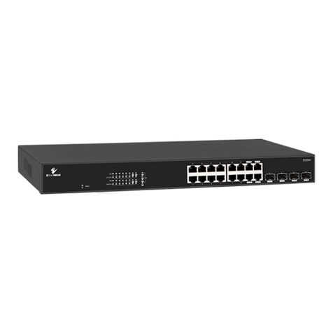
➢24 10/100/1000Base-TX PoE ports
➢4 1G SFP or 4 1G/10G SFP slots
10/100/1000Base-TX Ports
Ports that support Power over Ethernet provide power to networked
devices such as IP Phones, Wireless LAN Access Points, and IP security
cameras. Total power budget is 720 Watts, 60 Watts per port.
1G/10G SFP Slots
SFP transceivers can be installed directly into SFP slots. Ensure that the
same type of transceiver is used at both ends of the link and that the
correct type of fiber cable is used.
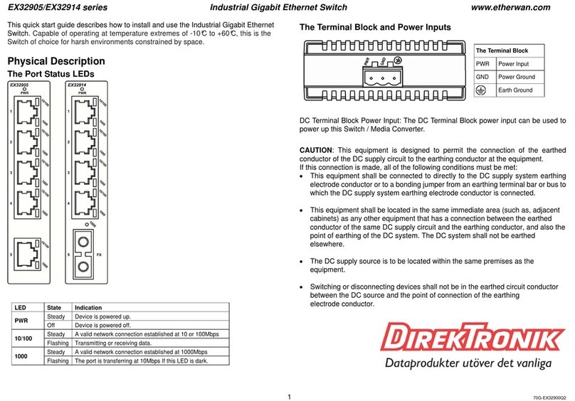
5 Apply DC Power
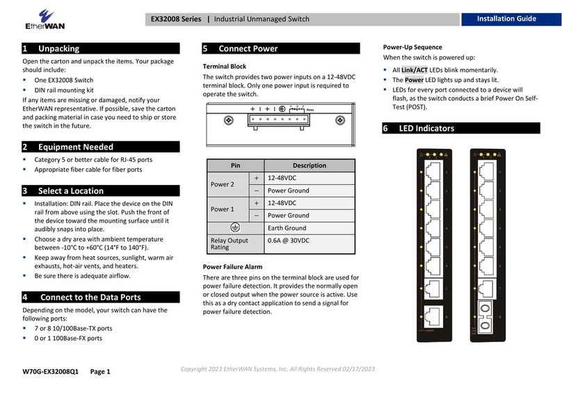
The switch has two terminal block power inputs. Only one power input is
required to operate the switch. However, redundant power supply
functionality is supported. Input voltage is 52-57 VDC.
Relay Output Alarm
The switch provides relay output contacts for signaling of a user-defined
power or port failure. The relay output can be connected to an alarm
signaling device. Current is 0.5A at 48VDC.
Power-Up Sequence
When you apply DC power:
➢All Link/ACT LEDs blink momentarily.
➢The Power LED goes ON.
➢Booting ⮕The Alarm LED goes ON
➢System ready ⮕The Alarm LED goes off
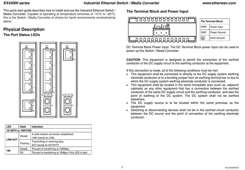
6 Front Panel LEDs
LED
Color
Status
Power
1&2
Green
ON = power on
OFF = power off
Link/ACT
Green
ON = Valid network connection is
established
Flashing = Port sending or receiving data
PoE
Amber
ON = Powered Device is connected
Off = Powered Device is disconnected
Alarm
Red
Link down or power down
EX75900 Series Hardened Managed PoE Ethernet Switch
Installation Guide
EX75900 Hardened Managed PoE Ethernet Switch
Copyright 2020 EtherWAN Systems, Inc. Page 2
All Rights Reserved
EX75900
03/19/2020
W70G-EX75900Q2
7 Console Configuration
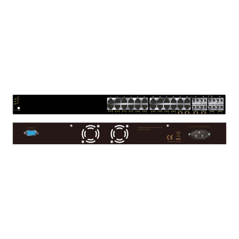
Connect to the switch console by connecting the DB-9 cable to the
console port of the switch and to the serial port of the computer running
a terminal emulation application (such as HyperTerminal or Putty).
Configuration settings of the terminal-emulation program: Baud rate:
115,200bps, Data bits: 8, Parity: none, Stop bit: 1, Flow control: none.
The default login name is “root,” no password.
8 Web Configuration
Connect to the switch using either one of the RJ45 ports on the front, or
the console port on the rear of the device.
Log in to the switch by launching a web browser and entering
192.168.1.10 in the address bar. Enter the default login ID: root (no
password) and click “Login.”
9 Copy Configuration to USB
The USB port can be used to save the running switch configuration to a
(FAT32) USB storage device. Plug the device into the USB port, and use
the “Save Configuration” command in the web interface, or “copy
running-config startup-config” in the CLI.
10 Digital IO-Setting
Connecting the Digital Inputs
The pin definitions for the digital input module are shown below. Each
digital input consists of two contacts on the 5-pin connector located on
the back panel of the switch. The inputs can be wired as either dry or
wet contacts.
Dry Contacts:
[DI1-/GND] [DI2-/GND]
Logic level 1: Close to GND
Logic level 0: Open
Wet Contacts:
[DI1+/DI1-] [DI2+/DI2-]
Logic level 1 (High): 13~30 Volts
Logic level 0 (Low): 0~3 Volts
11 Safety information
This equipment is intended to be used in a restricted access location and
by qualified personnel. This equipment is not suitable for use in locations
where children are likely to be present.
Pluggable optical modules and direct-attach cables shall meet the
following regulatory requirements:
• UL and/or CSA registered component for North America
• Class 1 Laser Product
• FCC 21 CFR Chapter 1, Sub-chapter J in accordance with FDA & CDRH
requirements
• IEC/EN 60825-1:2014, IEC/EN 60825-2:2004+A1+A2 or later, European
Standard
(A) Elevated Operating Ambient - If installed in a closed or multi-unit
rack assembly, the operating ambient temperature of the rack
environment may be greater than room ambient. Therefore,
consideration should be given to installing the equipment in an
environment compatible with the maximum ambient temperature (Tma).
B) Mechanical Loading - Mounting of the equipment in the rack should be
such that a hazardous condition is not achieved due to uneven
mechanical loading.
C) Circuit Overloading - Consideration should be given to the connection
of the equipment to the supply circuit and the effect that overloading of
the circuits might have on overcurrent protection and supply wiring.
Appropriate consideration of equipment nameplate ratings should be
used when addressing this concern.
D) Reliable Earthing - Reliable earthing of rack-mounted equipment
should be maintained. Particular attention should be given to supply
connections other than direct connections to the branch circuit (e.g. use
of power strips).
Do not disable the power cord grounding plug. The grounding plug is an
important safety feature.
Les matériels sont destinés à être installés dans des EMPLACEMENTS À
ACCÈS RESTREINT.
Power wiring information:
The rating of the power wire used must be at least 105°C.
USE COPPER CONDUCTORS ONLY.
If the equipment is used in a manner not specified by the manufacturer, the
protection provided by the equipment may be impaired.
WARNING –Explosion hazard. Do not disconnect the terminal block while the
circuit is live or unless the area is known to be free of ignitable
concentrations.
For repair or maintenance needs, contact EtherWAN directly.
Informations de câblage d'alimentation:
Le calibre du fil d'alimentation utilisé doit être d'au moins 105°C.
DESTINÉ À ÊTRE UTILISÉ AVEC DES CONDUCTEURS EN CUIVRE SEULEMENT.
Si la méthode d'utilisation de l'équipement diffère de celle décrite par le
fabricant, la protection assurée par l'équipement risque d'être altérée.
Contactez-nous pour l'entretien ou la reparation.
Manufacturer information:
ETHERWAN SYSTEMS, INC.
33F, No. 93, Sec. 1, Xintai 5th Rd., Xizhi Dist., New Taipei City, 221
Taiwan
Hazardous voltages may occur within this unit when
connected to all power supplies.
Plug the power cord into a grounded (earthed) electrical
outlet that is easily accessible at all times.

This manual suits for next models

1

Other EtherWAN Switch manuals

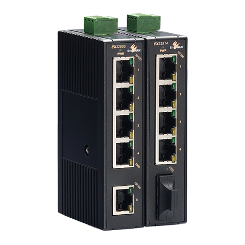
EtherWAN EX32905 Series User manual

EtherWAN

EtherWAN EX32905 Series User manual

EtherWAN EX78600 User manual

EtherWAN

EtherWAN EX78600 User manual

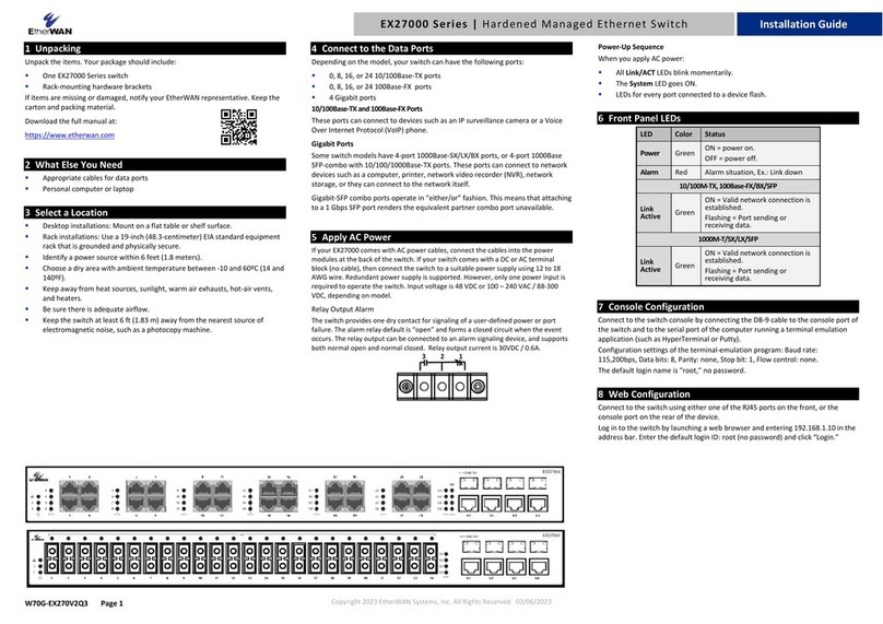
EtherWAN EX77000 Series User manual

EtherWAN

EtherWAN EX77000 Series User manual

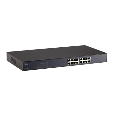
EtherWAN EX42395AT User manual

EtherWAN

EtherWAN EX42395AT User manual

EtherWAN EX17908 Series User manual

EtherWAN

EtherWAN EX17908 Series User manual

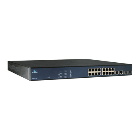
EtherWAN EX75900 Series User manual

EtherWAN

EtherWAN EX75900 Series User manual

EtherWAN EX93000 User manual

EtherWAN

EtherWAN EX93000 User manual

EtherWAN TG103H User manual

EtherWAN

EtherWAN TG103H User manual

EtherWAN EX26262F User manual

EtherWAN

EtherWAN EX26262F User manual

EtherWAN EX16908 User manual

EtherWAN

EtherWAN EX16908 User manual

EtherWAN EX78162 Series User manual

EtherWAN

EtherWAN EX78162 Series User manual

EtherWAN EX19082 User manual

EtherWAN

EtherWAN EX19082 User manual

EtherWAN EX78900X Series User manual

EtherWAN

EtherWAN EX78900X Series User manual

EtherWAN EX70900 User manual

EtherWAN

EtherWAN EX70900 User manual

EtherWAN EX26484 User manual

EtherWAN

EtherWAN EX26484 User manual

EtherWAN EX87000 Series User manual

EtherWAN

EtherWAN EX87000 Series User manual

EtherWAN EX46910F User manual

EtherWAN

EtherWAN EX46910F User manual

EtherWAN EX17082 User manual

EtherWAN

EtherWAN EX17082 User manual

EtherWAN EX42300 series User manual

EtherWAN

EtherWAN EX42300 series User manual

EtherWAN EX17082A User manual

EtherWAN

EtherWAN EX17082A User manual

EtherWAN EX25611 User manual

EtherWAN

EtherWAN EX25611 User manual

EtherWAN EG99000 Series User manual

EtherWAN

EtherWAN EG99000 Series User manual

EtherWAN EX42914 Series User manual

EtherWAN

EtherWAN EX42914 Series User manual

EtherWAN ER52000 User manual

EtherWAN

EtherWAN ER52000 User manual

Popular Switch manuals by other brands

A-Neuvideo ANI-16-4K60-S instruction manual

A-Neuvideo

A-Neuvideo ANI-16-4K60-S instruction manual

Planet IKVM-8000 user manual

Planet

Planet IKVM-8000 user manual

Black Box SW542A manual

Black Box

Black Box SW542A manual

AirLive ETHER-GSH2404W user manual

AirLive

AirLive ETHER-GSH2404W user manual

Advantech EKI-2526PI user manual

Advantech

Advantech EKI-2526PI user manual

Comtech EF Data CRS-170A Installation and operation manual

Comtech EF Data

Comtech EF Data CRS-170A Installation and operation manual

Quark-Elec QK-R043 manual

Quark-Elec

Quark-Elec QK-R043 manual

Phoenix Contact SWITCH 1008E Installation notes for electricians

Phoenix Contact

Phoenix Contact SWITCH 1008E Installation notes for electricians

Varilight V-Pro IR instructions

Varilight

Varilight V-Pro IR instructions

Cisco 500 Series quick start guide

Cisco

Cisco 500 Series quick start guide

Chroma Magic Box user manual

Chroma

Chroma Magic Box user manual

AVARRO 0E-HDMIMX4 manual

AVARRO

AVARRO 0E-HDMIMX4 manual

Comtrend Corporation GS-7608 user manual

Comtrend Corporation

Comtrend Corporation GS-7608 user manual

IOGear MiniView GCS78 quick start guide

IOGear

IOGear MiniView GCS78 quick start guide

GarrettCom Magnum 14E Installation and user guide

GarrettCom

GarrettCom Magnum 14E Installation and user guide

H3C S9500E Series Configuration guide

H3C

H3C S9500E Series Configuration guide

Hirschmann MSM20 user manual

Hirschmann

Hirschmann MSM20 user manual

Johnson Controls OLS-2000 Product/Technical Bulletin

Johnson Controls

Johnson Controls OLS-2000 Product/Technical Bulletin

manuals.online logo
manuals.online logoBrands
  • About & Mission
  • Contact us
  • Privacy Policy
  • Terms and Conditions

Copyright 2025 Manuals.Online. All Rights Reserved.