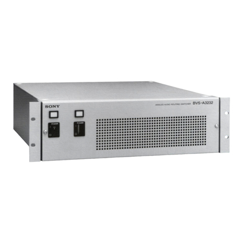
Sony SB-V60S User manual

SONY:
2-177-408-11
(1)
TV
!
Televiseur!
Televisor
Display device
Equipement
d'affichage
Dispositivo
de
visualizacion
AV
Selector
tt
tTo INPUT jack
vers
la
prise INPUT
ala
toma
INPUT
Operating
Instructions
Mode
d'emploi
Manual
de
instrucciones 1
5-Video/Audio
cable
(not
supplied)
Cable
5-Video/Audio
(non
fourni)
Cable
S·Video/Audio
(no
suministrado)
F======="""
Recording device
VCR,
etc. !
Equipement
Magnetoscope, etc. !
d'enregistrement
'=.-_V_C_R_,_e_t_c.
__
.....
Dispositivo
de
grabacion
To INPUT jack t t
vers la prise INPUT
ala
toma
INPUT
t
tt
tTo OUTPUT jack
vers
la
prise OUTPUT
a
la
toma
OUTPUT
23
To OUTPUT jack
vers la prise OUTPUT
a
la
toma
OUTPUT
$-Video/Audio
cable
(not
supplied)
Cable
5-Video/Audio
(non
fourni)
Cable
5-Video/Audio
(no
suministrado)
4
When
you
do
not
use
the
5-VIDEO jack, use
the
VIDEO
jack
with
a
video
cable instead
of
an
S-
Video
cable.
Lorsque
VOU5
n'utilisez
pas la
prise
5-VIDEO,
utilisez
la prise VIDEO
avec
un
cable
video
au
lieu
d'un
cable
S-Video.
Cuando
no
uti
lice
fa
toma
5-VIDEO,
utilke
la
toma
VIDEO con
un
cable
de
video
en
lugar
de
un
cable 5-Video.
VideolAudio
cable
(not
supplied)
Cable
Videol
Audio
(non
fourni)
Cable
Videol
Audio
(no
suministrado)
5-Video/Audio
cable
(not
supplied)
Cable
S-Video/Audio
(non
fourni)
Cable
S-Video/Audio
(no
suministrado)
!-!-!-!-!-~
,------------------------------
~-~-~
C!!~!~ll~!iC~!L~!i:C!!»!~1
tt
t
I~!!~I
t t t
?V
SB-V60S
http://www.sony.net!
©2005 Sony Corporation Printed
in
China
For
the
customers
in
the
USA
Owner's
Record
The
model
and
serial
numbers
are
located
on
the
bottom.
Record the serial
number
in
the
space
provided
below. Refer to
them
whenever
you
call
upon
your
Sony
dealer
regarding
this
product.
Model No. SB-V60S
Serial No. _
Satellite Receiver I
Re<:epteur
satellite
I
Receptor
de
satelite
Front
panel!
Panneau
avant!
Panel
frontal
---------------------------------------------------\
l~~t~~rlti~~/I
~_
1
Reproductor
de
DVD
..
_ :
Q~.
:
Playback device :
Equipement
de
lecture
Video
game!
:
Dispositivo
de
reproduccion Console
de
jeux
video!:
,
Y2~~~L~~~~~
:
=!::>..: Signal
flow!
sens
du
signal!
flujo
de
la senal
Front
panel!
Panneau
avant!
Panel
frontal
Rear
panel!
Panneau
arriere
!Panel
posterior
~
__
5-VlDEO VIDEO l..Jll)l)lO.R
To OUTPUT jack
vers
la
prise OUTPUT
ala
toma
OUTPUT
~
Video/Audio
cable
(not
supplied)
Cable
Video/Audio
(non
fourni)
Cable
Video/Audio
(no
suministrado)
Camcorder, etc.
Camescope, etc.
Videocamara, etc.

English
WARNING
To
prevent fire
or
shock hazard. do not expose
the unit
to
rain
or
moisture.
To
avoid electrical shock. do not open the
cabinet.
Refer servicing
to
qualified personnel only.
Before
using
the
AV
selector
On recording
Before
starting
to
record,
test
the
recording
function
to
make
sure
the
picture
and
sound
are
recorded
without
any
problems.
No guarantee for lost
or
damaged contents
Compensation
for
the
recording
contents
cannot
be
provided,
even
if
recording
or
playback
is
not
possible
due
to a
malfunction
of
a
camcorder,
storage
media,
etc.
Copyrights
Television
programs,
films,
videotapes,
and
other
materials
may
be
copyrighted.
Unauthorized
recording
of
such
materials
may
be
contrary
to
copyright
laws.
Copy guard function
Programs
received
through
an
external
tuner
may
contain
copy
protection
signals
(copy
guard
function)
and
as
such
may
not
be
recordable.
Precautions
Notes on
use
•Connect the plug securely. Incorrect connection may
cause noise or picture blur.
•To disconnect the cable,
grasp
the
plug
itself; never
pull the cable.
•
If
you place the unit on a
TV,
interference may occur.
In this case, adjust cable layout.
If
the problem
persists,
move
the unit.
•Do not install the unit at
an
inclined position.
•When connecting AV cables, take care to lay them
out so that they
are
not tripped over.
•Refer to the Operating Instructions of the device that
is to be connected.
Cleaning
the
cabinet
of
the
main unit
Lightly wipe the cabinet with asoft, dry cloth.
If
the
cabinet
is
badly soiled,
wipe
with asoft cloth
moistened with amild, diluted detergent, then wipe
off any remaining moisture with a soft,
dry
cloth.
If
you use achemical cloth, follow its instructions.
To
avoid damage to the unit's surface, observe the
following:
-Do not use alcohol, thinner or benzine.
-Do not spray.insecticide
or
hair spray
on
the unit.
-Do not leave in contact with chemical based
materials, such as insecticide, rubber, or vinyl.
Features
The
unit
is
an
AV
selector
equipped
with
4
inputs
and
2
outputs.
•All
inputs
and
outputs
equipped
with
the
S-
VIDEO
jacks
(S-VIDEO/VIDEO/
AUDIO-L/
AUDIO-R)
I
PUT
x
4:
for
playback
devices,
such
as
Satellite
receiver
or
DVD
player,
etc.
(lNPUT3
is
switchable
between
the
front
and
rear
panel)
MONITOR
OUT
x
1:
for
display
device,
such
as
TV, etc.
REC
OUT
xI:
for
recording
device,
such
as
VCR,
DVD/HDD
recorder,
etc.
•
Convenient
front
input
jacks to
connect
portable
devices,
such
as
a
camcorder,
etc.
•
Outputs
two
signals
to
two
devices
simultaneously.
•Slim
design:
allows
you
to install
the
unit
in
a
narrow
space.
•
Ergonomic
front
panel
design.
•
Passive
type
-
requires
no
power
supply.
Locating
the
Parts
and
Controls
(see
fig.
B>
Front panel
[I]
INPUT
SELECT
buttons
for
MONITOR
OUT
Press
one
of the INPUT
[II
-
~
buttons to select
the
input
to be
output
to MONITOR OUT for
displaying
on
a
TV
or
monitor, etc.
[l]
INPUT
SELECT
buttons
for REC
OUT
Press one of the INPUT III-
illJ
buttons to select
the
input
to be
output
to
MONITOR OUT for
recording to a
DVD/HDD
recorder
or
VCR, etc.
~
REC
OUT
OFF
button
Turn
off all INPUT SELECT
buttons
for
REC
OUT.
@]
INPUT
~
FRONT/REAR
bullon
Switches the effective INPUT3 jack between the
rear
and
front panels.
[§]
INPUT3
jack
S-VIDEO /VIDEO /AUDIO-L /AUDIO-R
Connect to the
output
jacks of avideo
game
or
camcorder.
Rear panel
[I]
MONITOR
OUT
jack
S-VIDEO /VIDEO /AUDIO-L /AUDIO-R
[l]
REC
OUT
jack
S-VIDEO /VIDEO /AUDIO·L /AUDJO-R
~
INPUT
1 - 4 jacks
S-VIDEO /VIDEO /AUDIO-L /AUDIO-R
How
to
use the supplied labels
To
determine
which
device
is
connected
where
without
checking
the
rear
panel,
put
labels
on
the
front
panel
of
the
unit. You
can
use
plain
labels
marked
with
an
oil-based
ink
pen.
Connections
{see
fig.
m>
Connect
aTV,
monitor,
VCR,
DVD/HDD
recorder,
satellite
receiver, etc.
to
the
unit
by
Video/
Audio
cables
(not
supplied).
If
the
device
to
be
connected
has
an
S-VIDEO jack,
you
can
use
an
S-Video cable for
improved
picture
quality.
Notes
•Connect the devices to the wall outlet after
connecting the devices to the unit.
•S-video signal will only
be
output
if connected to the
S-VIDEO jack with an S-Video cable.
Connection
example
1Connect
the
input
jack
of
a
display
device
to
the
MONITOR OUT jack
of
the
unit,
2Connect
the
input
jack
of
a
recording
device
to
the
REC
OUT jack
of
the
unit.
3Connect
the
output
jack
of
the
connected
recording
device
to
the
INPUT4 jack
of
the
unit.
4Connect
the
output
jacks
of
playback
devices
to
the
INPUT1 - 3 jacks
of
the
unit.

English
There
is
no
picture.
•
The
recording
device is incorrectly
connected
to the INPUT jack
of
the unit.
-+
Check
the connection again.
•Your TV
or
monitor
is
not
connected
to the
MONITOR
OUT
jack
of
the
unit.
-+
Check the connection again.
•
The
TV
or
monitor
input
is incorrectly set.
-+
Set
the
TV
or
monitor
input
correctly.
-+
Set
the
video
signal
input
correctly
according
to
whether
S-Video
or
regular
video
signal is used.
Avideo signal
is
not recorded.
•
The
playback
or
recording
devices
are
incorrectly
connected.
-+
Check the connection again.
•
The
input
select
of
the
recording
device
is incorrectly selected.
-+
Set
the
input
of
the
recording
device to LINE.
•
The
INPUT SELECT
buttons
for REC
OUT
are
incorrectly selected.
-+
Check the connection
of
the
playback
and
recording
devices
again,
and
select the INPUT SELECT
buttons
for REC OUT.
Signal
flow
The illustration
shows
signal flow for the
above
procedure.
The
unit
The
input you
want
to
display
is
not selected correctly.
•
The
recording
device is incorrectly
connected
to the INPUT jack
of
the
unit.
-+
Check
the
connection again.
•
INPUT
SELECT
buttons
for REC
OUT
are
pressed.
-+
Press the REC
OUT
OFF
button
when
using
the
device
connected
to
the
MONITOR
OUT
jack only.
Specifications
Input
S-
VIDEO 4-pin mini DIN x4
VIDEO PHONO jack x4
AUDIO
L/R
PHONO jack x4
(INPUT3 is switchable between the front
and
rear panel)
Output
S-VTDEO
4-pin mini DIN x2
VIDEO PHONO jack x2
AUDIO
L/R
PHONO jack x2
Dimensions (approx.)
430
x
42
x
231
mm (17 x
1"/
16 x91/8in.)
(w/h/d)
including projecting parts
Mass (approx.)
2
kg
(4
lb. 7oz.)
Operating
temperature
O°C
to
40"C
(32"F
to
1
04"F)
Supplied accessories
Operating Instructions
(1),
Label
(1),
Warranty (1)
Picture/sound distortion
occurs.
•
The
connection is incomplete.
-+
Check
the
connection again.
•
Two
INPUT SELECT
buttons
for MONITOR
OUT
or
REC
OUT
are
pressed
simultaneously.
-+
Press
only
one
INPUT SELECT
button
for
MONITOR
OUT
or
REC
OUT.
To
display adifferent signal
on
TV
Select
another
device
you
want
to
display
by
pressing
an
INPUT SELECT
button
for MONITOR OUT.
In the
above
example,
you
can
send
aDVD
player
or
video
game
signal to
the
TV
by
pressing
the
INPUT2
or
INPUn
button
for
MONITOR
OUT.
Troubleshooting
Should
any
problem
persist after you
have
checked
these
symptoms,
consult
your
nearest
Sony
dealer.
160001
TV
VCR,etc L
1
<-----I
2
I
2
_of
I
~t~
(~
.,d
•
~
--_.
ISatel.lite I
INPun
MONITOR
OUT
Receiver
I
IINPUT2
DVD
player
~
IIINPUT3
Video
game
I
INPUT4
RECOUT
~
I
_.
.
~
Note
Be
slife
to
connect the device connected
to
the
REC
OUT jack
to
the INPUT4 jack.
The unit
Signal
flow
The illustration
shows
signal flow for the
above
procedure.
Front panel
1Ready each device.
CD
Turn
on
the satellite receiver
and
TV.
®Set the TV's
input
that is connected to the unit.
2Press
the
INPUT1
button
of
the
INPUT
SELECT
buttons
for
MONITOR
OUT
to
send
the
satellite
receiver signal
to
the
TV.
3Play back
or
receive asignal
with
the
device selected
in
step
2.
Select a
program
on
the satellite receiver.
The
selected
program
plays
back
on
the TV.
Recording
Note
The program may not display properly on the
TV
if the device selected in step 2is also
set for the
REC
OUT jack.
In
this case, press the
REC
OUT OFF button to turn off the
INPUT
SELECT
button for
REC
OUT.
Output
asignal to
two
devices simultaneously.
This section explains
how
to
output
asatellite receiver signal to arecording
device connected to
the
REC
OUT
jack
of
the unit
and
to
output
the
same
signal
toa
TV.
For details, see the illustration
of
"Connections."
Front panel
1Ready each device.
CD
Turn
on
the satellite receiver, TV
and
VCR.
®Set the TV's
and
VCR's
inputs
that
are
connected
to the unit.
2Press
the
INPUT1
button
of
the
INPUT
SELECT
buttons
for
REC
OUT
to
send
the
satellite
receiver signal
to
the
VCR.
3Press
the
INPUT4
button
of
the
INPUT
SELECT
buttons
for
MONITOR
OUT
to
send
the
satellite
receiver signal
to
the
TV.
The selected
program
plays
back
on
the
TV.
4Receive asignal
with
the
device selected
in
step
2.
The
selected
program
recorded
on
the VCR.
Displaying
Selects the connected playback device to
send
the
output
signal to the
MONITOR
OUT
jack of the unit, such
as
aTV, monitor, etc.
This section explains
how
to
output
asatellite receiver signal to aTV.
For details, see the illustration of "Connections."
Design and specifications are subject to change without notice.

VIDEO
DVD
HOD
VHS
GAME
CD
TUNER
VIDEO
DVD
HOD
VHS
GAME
CD
TUNER
VIDEO
DVD
HOD
VHS
GAME
CD
TUNER=="
VIDEO
DVD
HOD
VHS
GAME
CD
TUNER
VIDEO
DVD
HDD
VHS
GAME
CD
TUNER
"""""""""""'"
VIDEO
DVD
HDD
VHS
GAME
CD
TUNER
:===="""""='=
VIDEO
DVD
HDD
VHS
GAME
CD
TUNER
VIDEO
DVD
HDD
VHS
GAME
CD
TUNER
VIDEO
DVD
HDD
VHS
GAME
CD
TUNER
VIDEO
DVD
HDD
VHS
GAME
TV
AMP
VIDEO
DVD
HDD
VHS
GAME
TV
AMP
VIDEO
DVD
HDD
VHS
GAME
TV
AMP
VIDEO
DVD
HDD
VHS
TV TV
AMP
VIDEO
DVD
HDD
VHS
TV
TV="""''''='A'='=M:=P===
VIDEO
DVD
HDD
VHS
TV TV
AMP
VIDEO
DVD
HDD
VHS
AMP AMP AMP
2-320-155-02

,,1/,
11111 11111
11111
1111111111
11111
111111111111111
""11""
4-557-163-05
Accessory
LIMITED
WARRANTY
(u.s.
Only)
Sony
Electronics Inc.
("Sony")
warrants this product against defects in material
or
workmanship
for
the
time
periods and
as
set forth below. Pursuant
to
this Limited Warranty,
Sony
will, at its option,
(i)
repair the product
using
new
or
refurbished parts
or
(ii) replace the product
with
a
new
or
refurbished product. For purposes
of
this
Limited Warranty, "refurbished" means aproduct
or
partthat has been returned
to
its original specifications. In
the
event
of
a
defect,
these
are
your
exclusive
remedies.
Term: For aperiod
of
ninety
(90)
days
from
the original date
of
purchase
of
the product, Sony will, at its option,
repair
or
replace
with
new
or
refurbished product
or
parts, any product
or
parts determined
to
be defective.
This Limited Warranty covers
only
the hardware components packaged
with
the Product. It does not cover
technical assistance
for
hardware
or
software usage and it does
not
cover any software products
whether
or
not
contained in the Product; any such software
is
provided
"AS
IS" unless expressly provided
for
in any enclosed
software Limited Warranty. Please refer
to
the End User License Agreements included
with
the Product
for
your
rights and obligations
with
respect
to
the software.
Instructions:
To
obtain warranty service,
you
must
deliver the product, freight prepaid, in either its original
packaging
or
packaging affording
an
equal degree
of
protection
to
the
Sony
authorized service facility specified.
It
is
your
responsibility
to
backup
any
data,
software
or
other
materials
you
may
have
stored
or
pre-
served
on
your
unit.
It
is
likely
that
such
data,
software,
or
other
materials
will
be
lost
or
reformatted
during
service
and
Sony
will
not
be
responsible
for
any
such
damage
or
loss. Adated purchase receipt is
required. For specific instructions on
how
to obtain warranty service
for
your
product,
The Address
of
the Laredo Fulfillment Center is:
Laredo
Fulfillment
Center
10227 Crossroads Loop Suite B
Laredo,
TX
78045
Visit Sony's Web Site:
www.sony.com/service
Or call the
Sony
Customer
Information
Service
Center
1-800-222-S0NY
(7669)
For an accessory
or
part not available
from
your
authorized dealer, call:
1-800-488-S0NY (7669)
Repair
I
Replacement
Warranty:
This Limited Warranty shall apply
to
any repair, replacement part
or
replace-
ment
product
for
the remainder
of
the original Limited Warranty period
or
for
ninety
(90)
days, whichever is
longer.
Any
parts
or
product replaced under this Limited Warranty
will
become the property
of
Sony.
This LimitedWarranty
only
covers productissuescaused bydefectsin material
or
workmanship
during
ordinary
consumeruse; itdoes
not
cover product issues caused by anyother reason, including
but
not
limited
to
product
issues due
to
commercial use, acts
of
God, misuse, limitations
of
technology,
or
modification
of
or
to
any part
of
the Sony product. This Limited Warranty does
not
cover Sony products sold AS IS
or
WITH ALL FAULTS
or
consumables (such
as
fuses
or
batteries). This Limited Warranty is invalid
if
the factory-applied serial
number
has been altered
or
removed
from
the product. This Limited Warranty is valid
only
in the United States.
LIMITATION
ON
DAMAGES:
SONY SHALL NOT
BE
LIABLE
FOR
ANY
INCIDENTAL
OR
CONSEQUENTIAL
DAMAGES
FOR
BREACH
OF
ANY
EXPRESS
OR
IMPLIED WARRANTY ON THIS
PRODUCT.
DURATION OF IMPLIED WARRANTIES: EXCEPT TO THE EXTENT PROHIBITED BY APPLICABLE LAW,
ANY
IMPLIEDWARRANTY
OF
MERCHANTABILITY
OR
FITNESS
FOR
APARTICULAR PURPOSE ON THIS PRODUCT
IS
LIMITED
IN
DURATION
TO
THE
DURATION
OF
THIS WARRANTY.
Some
states
do
not
allow
the exclusion
or
limitation
of
incidental
or
consequential damages,
or
allow
limitations
on
how
long an implied warranty lasts, so the above limitations
or
exclusions
may
not
apply
to
you. This Limited
Warranty gives you specific legal rights and
you
may
have other rights which vary
from
state
to
state.
Printed in China
Table of contents
Other Sony Switch manuals

Sony
Sony MHC-5500 User manual

Sony
Sony HDS-X3700 User manual

Sony
Sony XVS-9000 User manual

Sony
Sony MCS-8M User manual

Sony
Sony MVS-8000X System User manual

Sony
Sony DFS-900M User manual

Sony
Sony MLS-X1 User manual

Sony
Sony DMX-SW1 - Bravia Input Link User manual

Sony
Sony HDS-7150 User manual

Sony
Sony DMX-SW1 - Bravia Input Link User manual
Popular Switch manuals by other brands

PCB Piezotronics
PCB Piezotronics IMI Sensors 685B Series Installation and operating manual

HP
HP A3100-8 v2 SI Configuration guide

H3C
H3C S5500-EI series Security configuration guide

TR
TR S2928F-C Quick installation guide

logika
logika WL-ZCSWNPW-S1322-02 product manual

D-Link
D-Link DGS-3224TGR - Switch Command line interface reference manual