Sony WRR-855A User manual

1
3-810-586-12(1)
UHF Synthesized Tuner Unit
WRR-855A
Model:
Operating Instructions
Before operating the unit, please read this manual thoroughly
and retain it for future reference.
1995 by Sony Corporation [U64] [U66] [U68]

2
Table of Contents
Owner’s Record
The model and serial numbers are located at the rear of the
unit. Record the serial number in the space provided below.
Refer to these numbers whenever you call upon your Sony
dealer regarding this product.
Model No. WRR-855A Serial No.
You are cautioned that any changes or modifications not
expressly approved in this manual could void your authority
to operate this equipment.
Notice for customers in Canada:
Use of Sony wireless devices is regulated by the
Industry Canada as described in their Radio Standard
Specification RSS-123.
A licence is normally required. The local district office of
Industry Canada should therefore be contacted. When the
operation of the device is within the broadcast band, the
licence is issued on no-interference, no-protection basis with
respect to broadcast signals.
Avis pour les clients au Canada:
L’usage des appareils sans-fil Sony est réglé par l’Industrie
Canada, comme décrit dans leur Cahier des Normes
Radioélectriques CNR-123. Une licence est normalement
requise. Le bureau de l’Industrie Canada doit être contacté.
Lorsque l’opération de l’appareil est dans les limites de la
bande de radiodiffusion, la licence est émanée sur la base
de non-interférence, non-protection avec les signaux de
radiodiffusion.
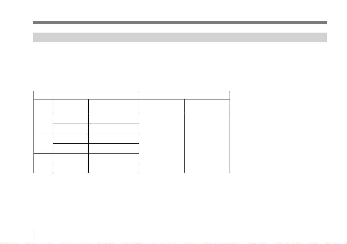
Overview........................................................................... 3
Features ........................................................................ 3
System Configuration .................................................. 4
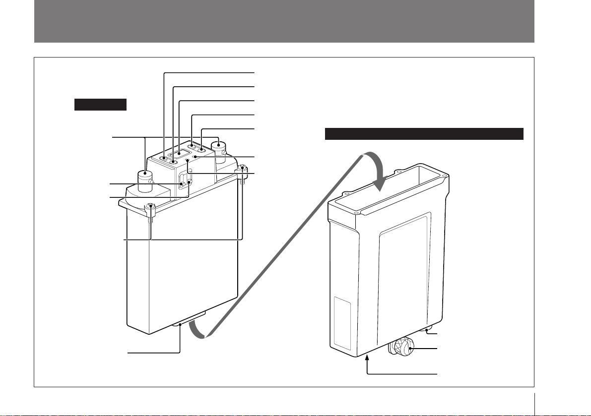
Parts Identification .......................................................... 5
WRR-855A .................................................................. 6
BTA-801 Portable Tuner Mount Adapter (Optional) .. 7
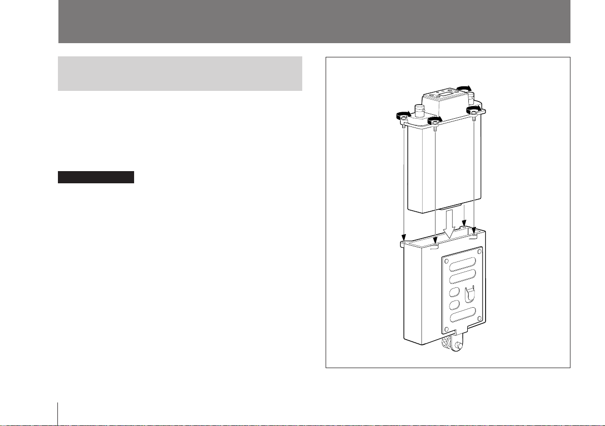
Preparations ..................................................................... 8
Mounting to a Portable Tuner Mount Adapter ............ 8
Connecting the Power Cable........................................ 9
Attaching the Antennas................................................ 9
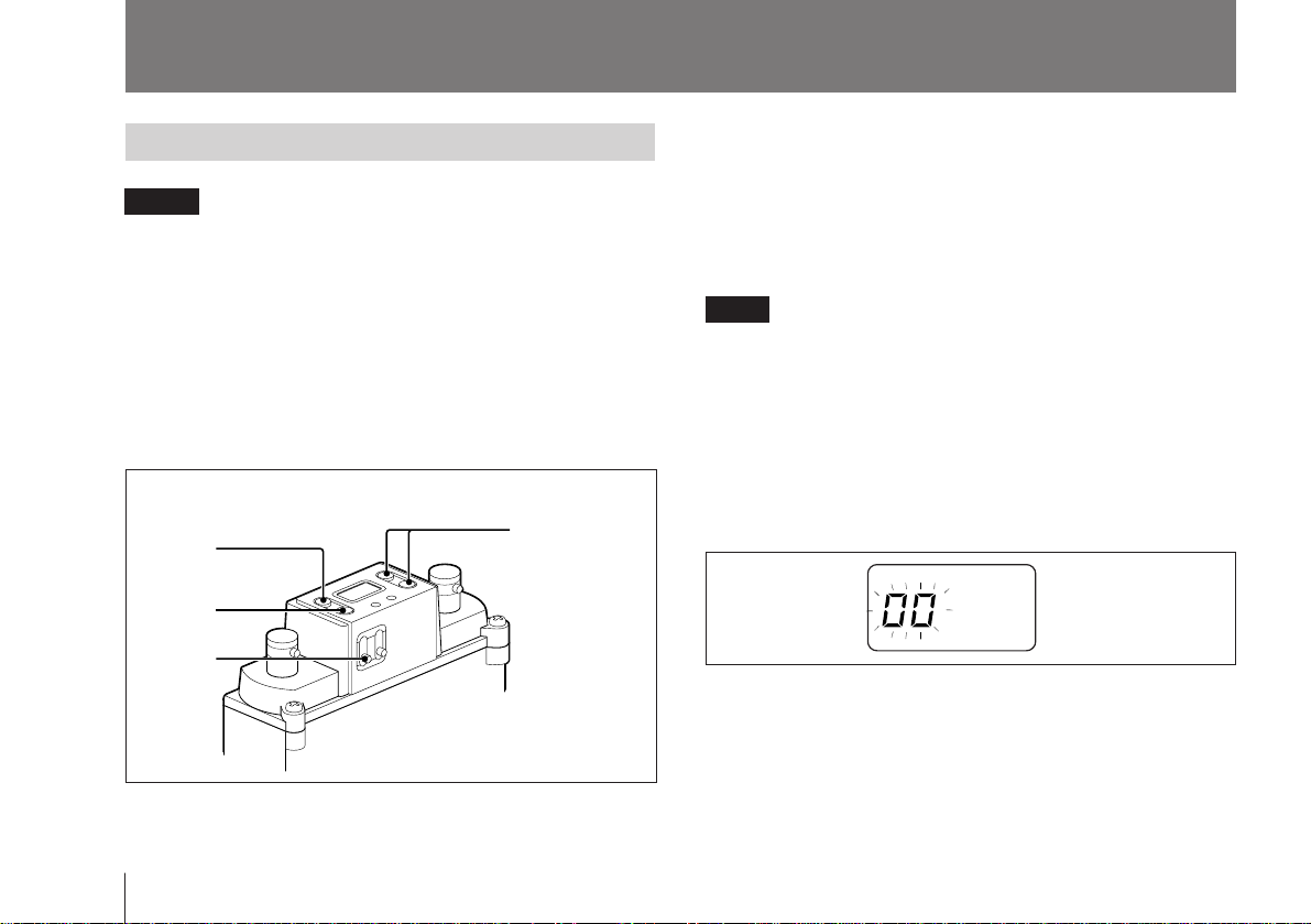
Setting ............................................................................. 10
Channel Selection ...................................................... 10
Selecting and Releasing the T (Tone Squelch) OFF
Mode .......................................................................... 13
Wireless Channel Selectable ......................................... 14
Guidance on Use of Multi-Channel System .............. 14
Wireless Channel Lists (1) – For 68-Version Model
Using TV Channels 68 and 69 ................................... 15
Wireless Channel Lists (2) – For 66-Version Model
Using TV Channels 66 and 67 ................................... 18
Wireless Channel Lists (3) – For 64-Version Model
Using TV Channels 64 and 65 ................................... 21
Attaching and Connecting to a Betacam ..................... 24
Precautions ..................................................................... 26
Messages on the Display................................................ 27
Specifications................................................... Back cover

3
Overview
Versatile display
A variety of information is obtained at a glance on the
upper panel, such as the reception channel with the liquid-
crystal display, and RF input level and audio level with the
respective LEDs.
Compact and lightweight
Innovative, high-density mounting technology has enabled
the creation of this compact, lightweight tuner. Using the
optional BTA-801 Portable Tuner Mount Adapter in
combination, the WRR-855A can be easily attached to a
Betacam-series Camcorder.
Weatherproof structure
By properly mounting the WRR-855A to the optional BTA-
801 Portable Tuner Mount Adapter and attaching the two
supplied antennas, a weatherproof structure is obtained.
Muting ON/OFF function
You can activate or deactivate the muting function to suit
your needs.
Tone-squelch circuit for noise elimination
The unit uses a built-in squelch circuit to selectively receive
the desired RF carrier accompanied by the tone signal from
the transmitter.
Compander system
A compander (compressor/expander) system enables
stabilized wireless transmission over a wide dynamic range.
The WRR-855A UHF Synthesized Tuner Unit in use with
an optional Portable Tuner Mount Adapter, such as the
BTA-801, provides a highly reliable portable diversity
tuner for the 800 MHz band Sony UHF wireless
microphone system, which uses the frequency bands
allocated for UHF TV broadcasting.
This tuner enables the application of multiple channels over
unused television channels through the use of the built-in
Sony original channel plan.
Features
Phase Locked Loop (PLL) Synthesized System
The WRR-855A with its refined PLL synthesized circuit
can operate on 94 wireless channels.
Preset wireless channel groups for easy multichannel
operation
In addition to a group allowing all 94 wireless channels to
be selected, the WRR-855A has six preprogrammed groups,
that is, a combination of wireless channels which permits
simultaneous operation of multiple channels without
intermodulation.
Space diversity reception system
The WRR-855A provides stable signal reception with only
a minute amount of dropout.

4
System Configuration
The WRR-855A can be used with the WRT-807A/810A/
830A/867A UHF synthesized wireless microphone or
WRT-808A/820A/822A/860A UHF synthesized
transmitter.
Overview
Sony 800 MHz band system models
a) These models cover only 68 and 69 channels.
b) For these models, the AN-820A UHF antenna and the WD-820A UHF antenna divider are required.
WRR-855A
a)
b)
b)
a)
a) a)
b)
Frequency band Model name
Model TV
channel Frequency (MHz) Transmitter or
microphone Tuner
U64 64 770.125 - 775.875 WRT-807A
WRT-808A
WRT-810A
WRT-820A
WRT-822A
WRT-830A
WRT-860A
WRT-867A
WRR-810A
WRR-820A
WRR-840A
WRR-850A
WRR-860A
65 776.125 - 781.875
U66 66 782.125 - 787.875
67 788.125 - 793.875
U68 68 794.125 - 799.875
69 800.125 - 805.875

5
UHF SYNTHESIZED
TUNER UNIT WRR-855
ON
OFF
MUTING
POWER
CH
GP
–
+
GP/CH
RF AF
S
Parts Identification
5Accessory connector
1ANT connectors
2POWER switch
3MUTING switch
8Liquid-crystal display
6GP button
!¡ AF indicator
!™ RF indicator
7CH button
9+ button
0– button
WRR-855A
BTA-801 Portable Tuner Mount Adapter (optional)
!£ DC 12V IN connector
!¢ Betacam attachment
knob
!∞OUTPUT connector
4Mounting screws (4)

6
5Accessory connector
For the signal and power connections with the BTA-801.
6GP (group set) button
Press and hold down for at least one second to go to the
group selection mode, and the group number flashes on the
display.
See “Setting” on page 10.
7CH (channel set) button
Press and hold down for at least one second to go to the
channel selection mode and the channel number flashes on
the display.
See “Setting” on page 10.
8Liquid-crystal display
When you turn the power ON, the “HELLO” message
appears, then the tuner unit goes to normal display mode.
9+ button / 0– button
Press to select the group and channel numbers to be
received.
See “Setting” on page 10.
1: AF GND
2: AF OUTPUT
4: DC +7V
5: GND
Pin assignment
8
1
15
9
Parts Identification
WRR-855A
1ANT (antenna) connectors
Connect the two supplied antennas to these connectors.
2POWER switch
Turns the power ON/OFF.
3MUTING switch
Turns the muting ON/OFF. The muting level is fixed at
10 dBµ.
Note
If you turn off the muting when the tuner is in standby
condition for signal receiving or when the RF input level is
low, noise may be heard or the connected device or
speakers may be damaged. Be sure to operate this switch
only after minimizing the input of the connected device.
4Mounting screws
Used to secure the WRR-855A to the BTA-801.
For mounting, see “Mounting to a Portable Tuner Mount
Adapter” on page 8.

7
!¢ Betacam attachment knob
Used to fix the unit to a Betacam.
For attaching the unit to a Betacam, see page 24.
!∞OUTPUT connector (XLR 3-pin, male)
Supplies audio signals. You can connect this to the
microphone input connector of a Betacam, mixer, tape
recorder or other similar equipment.
Note
When connecting to an audio mixer which has a Phantom
powering capability for microphones, it is recommended to
use the mixer with the Phantom power OFF.
!¡ AF (audio frequency level) indicator
Lights when an audio signal greater than the reference level
is output.
!™ RF (radio frequency input level) indicator
Displays the strength of the input signal.
Lights in green: Higher than 25 dBµ
Lights in red: 10 to 25 dBµ
Goes off: Lower than 10 dBµ
BTA-801 Portable Tuner Mount Adapter
(Optional)
!£ DC 12V IN (power input) connector
Connect to an external power supply (DC 10 to 17 V) of a
Betacam using the DC power cable supplied with the BTA-
801.
Note
Be sure to check the operating voltage and polarity when
connecting to a power source.
Pin assignment
3
1
2
1: GND
2: HOT
3: COLD
Pin assignment 1: GND
2: NC
3: NC
4: +12 V
2
3
41
2
3
41

8
Mounting to a Portable Tuner Mount
Adapter
This section shows you how to moung the WRR-855A to
the BTA-801 Portable Tuner Mount Adapter for example.
By properly mounting the WRR-855A to the BTA-801 and
attaching the two supplied antennas, a weatherproof
structure is obtained.
Before mounting
Be sure to clean the abutting surfaces of the WRR-855A
and the BTA-801 before mounting.
Procedure to mount to the BTA-801
1Observing the direction, insert the WRR-855A in the
BTA-801.
2Push the WRR-855A until the accessory connector
clicks into place.
3Run in the four mounting screws little by little in turn to
gradually secure the units together, then tighten them.
Preparations
WRR-855A
BTA-801

9
Connecting the Power Cable
Connect the DC 12 V IN connector of the BTA-801 to the
DC OUT connector of a Betacam-series Camcorder using
the DC power cable supplied with the BTA-801.
Attaching the Antennas
Attach the supplied antennas to the two ANT connectors.
DC power cable
(supplied with the BTA-801)
Match the connector pins
with the inside of the
connector and insert.
2Turn to lock.
1Align the protruding part
of the connector with the
antenna slot.
BTA-801 (bottom)
To remove: Pull the metal part of the connector in the
direction of the arrow and remove.

10
Setting
Operations
1Turn the POWER switch ON.
After the “HELLO” message, the tuner status shown
before the tuner was previously turned OFF appears on
the display.
Note
POWER switch operation should be performed after
disconnecting the input from connected equipment, as noise
will be heard if the switch is turned ON or OFF beforehand.
2Press and hold the GP button down for more than one
second.
The tuner goes to the group selection mode and the
group number flashes.
Channel Selection
Notes
Take the following precautions to prevent interference and
noise.
• Do not simultaneously use two or more microphones and
transmitters that are set to the same channel.
• When simultaneously using two or more tuners, always
set the tuners that use the same groups (other than group
00) to different channels in that group.
• The reception antennas and transmitter should be used at
least 3 meters away from each other.
Operations
UHF SYNTHESIZED
TUNER UNIT WRR-855
ON
OFF
MUTING
POWER
CH
GP
–
+
GP/CH
RF AF
S
2
4
1
3,5

11
3Press the + or – button to select the group.
Pressing the + button cyclically changes the groups in
the order of 00 to 11 to 12 to 13 to A1 to A2 to A3 to L1
to L2 to H1 to H2 and pressing the – button changes
them in the reverse order.
Press and hold down the button to continuously change
the display.
If no buttons are pressed for 5 seconds, the group
selection mode is automatically canceled and the lowest
frequency channel in the group selected at that time is
displayed.
For Group 00, however, the channel previously set in
Group 00 appears.
4Press the CH button when the desired group is displayed.
The tuner goes to the channel selection mode and the
channel number flashes.
5Press the + or – button to select the channel.
Pressing the + button cyclically changes the channels of
the group selected in step 3 in the listed order in the
respective table in the “Wireless Channel Lists” on pages
15 to 23. Pressing the – button changes them in the
reverse order.
When you reach the last channel in the group, press the +
button to return to the first channel in the group.
Likewise, press the – button to go from the first channel
to the last channel.
When the group is set to 00, press either of these buttons
to move through the 94 channels one by one.
¿÷
– button
+ button
(Continued)
– button + button
÷
¿
...
Display example
for U68 model
Display example for U68 model

12
Distortion-check function
Before operating a wireless microphone or transmitter, you
can check for possible distortion by using the distortion-
check function of this unit. To check the distortion,
simultaneously press the + and – buttons in the channel
selection mode (the channel number flashes). The channels
of the selected group are automatically switched one by one
in sequence (this operation is called “scanning”).
Notes
• When the MUNING switch is ON and the unit is not in
the T OFF mode (see page 13), scanning stops and the
channel at that time is selected if a tone signal (32.768
kHz) is detected in the signal received during scanning.
However, scanning will not stop if a distorting signal
having no tone signal is received.
In this case, check for the distortion by observing the RF
input level indicator.
• Scanning is automatically canceled when all the channels
of the selected group are scanned twice. To cancel
scanning in progress, press any of the operation buttons.
• If an extremely strong signal is received, scanning may
stop at a point other than the actual channel.
Setting
6After the desired channel is displayed, leave the unit for
5 seconds without pressing any buttons.
Channel selection mode is automatically canceled and
the channel (or frequency) shown on the display is set.
Storing the group and channel
The selected group and channel set by the above procedure
are stored in memory when the display stops flashing.

13
Setting and Releasing the T (Tone Squelch) OFF Mode
The WRR-855A has the following three muting functions,
which work in combination.
(1) Muting by RF input level: As sufficient S/N for the
audio output may not be obtained if no RF signal is
received or the RF input level is low, the audio output
can be muted when the RF input level falls below the
selected level.
(2) Tone squelch: The audio output is obtained only when
the tuner receives an RF signal which includes a
specified tone signal. The audio output is muted to
eliminate noise which may be heard when the
transmitter is turned on/off or the tuner receives an
interference RF signal.
(3) Noise squelch: The audio output is muted to eliminate
noise which may be heard when there is such excessive
interference RF signal that the tone squelch does not
work.
Only the muting functions described in (2) can be canceled
by selecting the Tone-squelch OFF (T OFF) mode when
desired. Apply this mode when you use a transmitter with
no specified tone signal.
Selecting the T OFF mode
Turn the power ON while pressing and holding the GP and
– buttons. Release the buttons after the “HELLO” message
appears. “T OFF” is momentarily displayed and the tuner
goes to the T OFF mode.
The T OFF mode is maintained even when the power is
turned OFF.
Resuming from the T OFF mode
To cancel the T OFF mode, turn the power ON while
pressing and holding the GP and + buttons, and release the
buttons after “HELLO” appears on the display.
“T ON” is momentarily displayed and the tuner resumes the
normal status.

14
Guidance on Use of Multi-Channel
System
This product is designed to give excellent interference free
operation in multi-channel systems. To maintain this, Sony
recommends that one of the original Sony groups, number
00, 11, 12, 13, A1, A2, A3, L1, L2, H1 or H2 is selected.
These groups will offer excellent performance, free from
mutual interference from other Sony wireless microphone
transmitters in the selected group when used under the
recommended operating conditions. The remaining groups
are included for compliance with frequency regulations in
various countries, and will not always guarantee
interference free operation.
Group 00 is used to scan for open channels, or to use only
for a one channel system.
Each “wireless channel” is represented on the unit by a 2-
digit TV channel number and another 2-digit number, for
example: 68-23.
Notes
To eliminate interference or noise, please note the
following.
•Do not use two or more wireless microphones or
transmitters whose wireless channels are the same.
•If there is a TV broadcasting station nearby, to avoid
possible interference from its broadcast, do not use that
station’s channel.
•The number of wireless channels actually usable in a
multi-channel system may be smaller than the normal
capacity of that system if there is interference from TV
broadcasting or other RF signals.
•To operate two or more UHF synthesized wireless
microphones/transmitters using the same wireless
channel of the same group, ensure that the wireless
microphones/transmitters are at least 100 m (330 feet)1)
apart as far as they are installed within sight of each
other.
•When using two or more WRR-855As, do not directly
put one unit upon the other.
...............................................................................................................................................................................................................................................
1) The distance depends on the operating environment and conditions.
Wireless Channels Selectable

15
lennahC)zHM(ycneuqerFlennahC)zHM(ycneuqerFlennahC)zHM(ycneuqerFlennahC)zHM(ycneuqerF
10-86521.49752-86521.79710-96521.00852-96521.308
20-86052.49762-86052.79720-96052.00862-96052.308
30-86573.49772-86573.79730-96573.00872-96573.308
40-86005.49782-86005.79740-96005.00882-96005.308
50-86526.49792-86526.79750-96526.00892-96526.308
60-86057.49703-86057.79760-96057.00803-96057.308
70-86578.49713-86578.79770-96578.00813-96578.308
80-86000.59723-86000.89780-96000.10823-96000.408
90-86521.59733-86521.89790-96521.10833-96521.408
01-86052.59743-86052.89701-96052.10843-96052.408
11-86573.59753-86573.89711-96573.10853-96573.408
21-86005.59763-86005.89721-96005.10863-96005.408
31-86526.59773-86526.89731-96526.10873-96526.408
41-86057.59783-86057.89741-96057.10883-96057.408
51-86578.59793-86578.89751-96578.10893-96578.408
61-86000.69704-86000.99761-96000.20804-96000.508
71-86521.69714-86521.99771-96521.20814-96521.508
81-86052.69724-86052.99781-96052.20824-96052.508
91-86573.69734-86573.99791-96573.20834-96573.508
02-86005.69744-86005.99702-96005.20844-96005.508
12-86526.69754-86526.99712-96526.20854-96526.508
22-86057.69764-86057.99722-96057.20864-96057.508
32-86578.69774-86578.99732-96578.20874-96578.508
42-86000.79742-96000.308
Wireless Channel Lists (1) – For 68-Version Model Using TV Channels 68 and 69
Group 00: All channel access
Use to scan for open channels. Use
only for a one channel system.

16
Wireless Channels Selectable
Group 11: 11-channel group
Use when both TV channels 68 and 69
are open.
Group 12: 8-channel group
Use when TV channel 69 is open. Group 13: 8-channel group
Use when TV channel 68 is open.
Group A1: 19-channel group
The channels listed as Group A1 for
the 66- and 64-version models can be
simultaneouly used in combination.
See “Group A1” on pages 19 and 22.
Group A2: 13-channel group
The channels listed as Group A2 for
the 66- and 64-version models can be
simultaneouly used in combination.
See “Group A2” on pages 19 and 22.
Group A3: 13-channel group
The channels listed as Group A3 for
the 66- and 64-version models can be
simultaneouly used in combination.
See “Group A3” on pages 19 and 22.
lennahC)zHM(ycneuqerF
50-86526.497
41-86057.597
52-86521.797
14-86521.997
74-86578.997
21-96005.108
61-96000.208
03-96057.308
73-96526.408
04-96000.508
24-96052.508
lennahC)zHM(ycneuqerF
10-96521.008
50-96526.008
11-96573.108
52-96521.308
82-96005.308
63-96005.408
14-96521.508
34-96573.508
lennahC)zHM(ycneuqerF
30-86573.497
31-86526.597
81-86052.697
62-86052.797
73-86526.897
04-86000.997
44-86005.997
64-86057.997
lennahC)zHM(ycneuqerF
60-86057.497
02-86005.697
42-86000.797
04-86000.997
40-96005.008
71-96521.208
32-96578.208
74-96578.508
lennahC)zHM(ycneuqerF
11-96573.108
22-96057.208
03-96057.308
63-96005.408
04-96000.508
34-96573.508
54-96526.508
lennahC)zHM(ycneuqerF
01-86052.597
12-86526.697
92-86526.797
53-86573.897
93-86578.897
24-86052.997
44-86005.997

17
Group L1: 7-channel
group
Use when TV channel 68 is
open.
Group L2: 7-channel
group
Use when TV channel 68 is
open.
Group H1: 7-channel
group
Use when TV channel 69 is
open.
Group H2: 7-channel
group
Use when TV channel 69 is
open.
Channel Frequency
(MHz)
68-09 795.125
68-11 795.375
68-19 796.375
68-25 797.125
68-30 797.750
68-34 798.250
68-37 798.625
68-10 795.250
68-13 795.625
68-17 796.125
68-22 796.750
68-28 797.500
68-36 798.500
68-38 798.750
69-09 801.125
69-11 801.375
69-19 802.375
69-25 803.125
69-30 803.750
69-34 804.250
69-37 804.625
69-10 801.250
69-13 801.625
69-17 802.125
69-22 802.750
69-28 803.500
69-36 804.500
69-38 804.750
Channel Frequency
(MHz) Channel Frequency
(MHz)

18
Wireless Channel Lists (2) – For 66-Version Model Using TV Channels 66 and 67
Group 00: All channel access
Use to scan for open channels. Use
only for a one channel system.
lennahC)zHM(ycneuqerFlennahC)zHM(ycneuqerFlennahC)zHM(ycneuqerFlennahC)zHM(ycneuqerF
10-66521.28752-66521.58710-76521.88752-76521.197
20-66052.28762-66052.58720-76052.88762-76052.197
30-66573.28772-66573.58730-76573.88772-76573.197
40-66005.28782-66005.58740-76005.88782-76005.197
50-66526.28792-66526.58750-76526.88792-76526.197
60-66057.28703-66057.58760-76057.88703-76057.197
70-66578.28713-66578.58770-76578.88713-76578.197
80-66000.38723-66000.68780-76000.98723-76000.297
90-66521.38733-66521.68790-76521.98733-76521.297
01-66052.38743-66052.68701-76052.98743-76052.297
11-66573.38753-66573.68711-76573.98753-76573.297
21-66005.38763-66005.68721-76005.98763-76005.297
31-66526.38773-66526.68731-76526.98773-76526.297
41-66057.38783-66057.68741-76057.98783-76057.297
51-66578.38793-66578.68751-76578.98793-76578.297
61-66000.48704-66000.78761-76000.09704-76000.397
71-66521.48714-66521.78771-76521.09714-76521.397
81-66052.48724-66052.78781-76052.09724-76052.397
91-66573.48734-66573.78791-76573.09734-76573.397
02-66005.48744-66005.78702-76005.09744-76005.397
12-66526.48754-66526.78712-76526.09754-76526.397
22-66057.48764-66057.78722-76057.09764-76057.397
32-66578.48774-66578.78732-76578.09774-76578.397
42-66000.58742-76000.197
Wireless Channels Selectable

19
Group 11: 11-channel group
Use when both TV channels 66 and 67
are open.
Group 12: 8-channel group
Use when TV channel 67 is open. Group 13: 8-channel group
Use when TV channel 66 is open.
Group A1: 19-channel group
The channels listed as Group A1 for
the 64- and 68-version models can be
simultaneouly used in combination.
See “Group A1” on pages 16 and 22.
Group A2: 13-channel group
The channels listed as Group A2 for
the 64- and 68-version models can be
simultaneouly used in combination.
See “Group A2” on pages 16 and 22.
Group A3: 13-channel group
The channels listed as Group A3 for
the 64- and 68-version models can be
simultaneouly used in combination.
See “Group A3” on pages 16 and 22.
lennahC)zHM(ycneuqerF
50-66526.287
41-66057.387
52-66521.587
14-66521.787
74-66578.787
21-76005.987
61-76000.097
03-76057.197
73-76526.297
04-76000.397
24-76052.397
lennahC)zHM(ycneuqerF
10-76521.887
50-76526.887
11-76573.987
52-76521.197
82-76005.197
63-76005.297
14-76521.397
34-76573.397
lennahC)zHM(ycneuqerF
30-66573.287
31-66526.387
81-66052.487
62-66052.587
73-66526.687
04-66000.787
44-66005.787
64-66057.787
lennahC)zHM(ycneuqerF
20-66052.287
42-66000.587
92-66526.587
61-76000.097
81-76052.097
93-76578.297
lennahC)zHM(ycneuqerF
70-76578.887
33-76521.297
54-76526.397
lennahC)zHM(ycneuqerF
60-66057.287
23-66000.687
44-66005.787

20
Group L1: 7-channel
group
Use when TV channel 66 is
open.
Group L2: 7-channel
group
Use when TV channel 66 is
open.
Group H1: 7-channel
group
Use when TV channel 67 is
open.
Group H2: 7-channel
group
Use when TV channel 67 is
open.
Channel Frequency
(MHz) Channel Frequency
(MHz)
66-09 783.125
66-11 783.375
66-19 784.375
66-25 785.125
66-30 785.750
68-34 798.250
68-37 798.625
66-10 783.250
66-13 783.625
66-17 784.125
66-22 784.750
66-28 785.500
66-36 786.500
66-38 786.750
67-09 789.125
67-11 789.375
67-19 790.375
67-25 791.125
67-30 791.750
67-34 792.250
67-37 792.625
67-10 789.250
67-13 789.625
67-17 790.125
67-22 790.750
67-28 791.500
67-36 792.500
67-38 792.750
Wireless Channels Selectable
Other manuals for WRR-855A
1
Table of contents
Other Sony Tuner manuals

Sony
Sony ST-S9 User manual

Sony
Sony ST-D777ES User manual

Sony
Sony ST-S770ES User manual

Sony
Sony WRR-855B User manual

Sony
Sony ST-S590ES User manual

Sony
Sony ST-SA50ES - Am/fm Tuner User manual

Sony
Sony WRR-861A User manual

Sony
Sony XT-V70 User manual

Sony
Sony ST-SV7 User manual

Sony
Sony Dream Machine ICF-C743 User manual

Sony
Sony URX-S03D User manual

Sony
Sony ST-JX410 - Fm/am Tuner User manual

Sony
Sony WRU-806B User manual

Sony
Sony ST-S500ES User manual

Sony
Sony WRR-862A User manual

Sony
Sony MB-8N Installation and operation manual

Sony
Sony WRR-805A User manual

Sony
Sony WRR-800A User manual

Sony
Sony Ipela NSR-S10 User manual

Sony
Sony FDL-3105 User manual