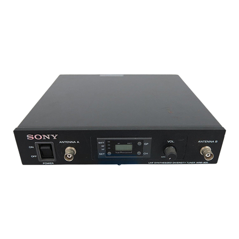
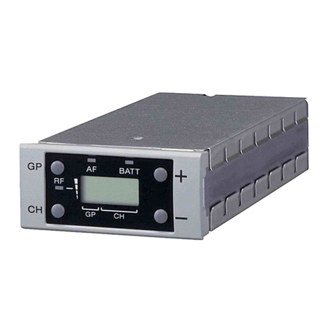
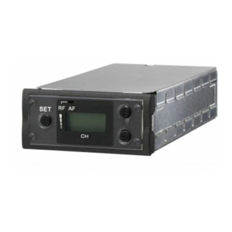
Sony WRR-801A User manual

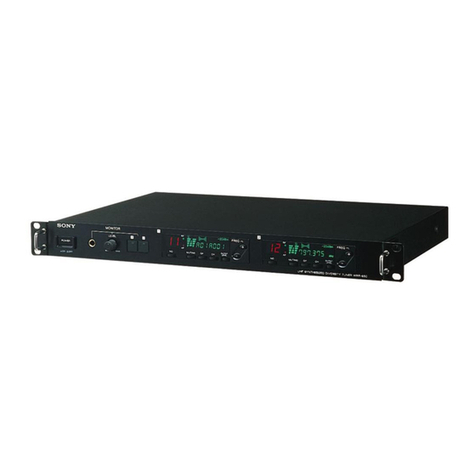
UHF SYNTHESIZED DIVERSITY TUNER
WRR-801A
SERVICE MANUAL
UHF SYNTHESIZED TUNER UNIT
WRU-801A
U Model

SAFETY CHECK-OUT
After correcting the original service problem,
perform the following safety checks before
releasing the set to the customer :
Check the metal trim, “metallized” knobs, screws,
and all other exposed metal parts for AC
leakage. Check leakage as described below.
LEAKAGETEST
The AC leakage from any exposed metal part to
earth ground and from all exposed metal parts to
any exposed metal part having a return to
chassis, must not exceed 0.5 mA. Leakage
current can be measured by any one of three
methods.
1. A commercial leakage tester, such as the
Simpson 229 or RCA WT-540A. Follow the
manufacturers’ instructions to use these
instruments.
2. A battery-operated AC milliammeter. The
Data Precision 245 digital multimeter is
suitable for this job.
3. Measuring the voltage drop across a resistor
by means of aVOM or battery-operated AC
voltmeter. The “limit” indication is 0.75 V, so
analog meters must have an accurate low-
voltage scale. The Simpson 250 and Sanwa
SH-63Trd are examples of a passive VOM
that is suitable. Nearly all battery operated
digital multimeters that have a 2 V AC range
are suitable. (See Fig. A)
Fig A. Using an AC voltmeter to check AC leakage.
To Exposed Metal
Parts on Set
1.5 k
Ω
0.15
µ
FAC
voltmeter
(0.75V)
Earth Ground
!WARNING
This manual is intended for qualified service personnel
only.
To reduce the risk of electric shock, fire or injury, do not
perform any servicing other than that contained in the
operating instructions unless you are qualified to do so.
Refer all servicing to qualified service personnel.

1
WRR-801A
WRU-801A
TABLE OF CONTENTS
1. OPERATING INSTRUCTIONS
2. SERVICE OVERVIEW
2-1. BOARDS LOCATION .................................................................................. 2-1
2-2. PRECAUTION IN WIRING HARNESS ...................................................... 2-1
2-3. ERROR MESSAGES ..................................................................................... 2-2
2-4. SERVICE FUNCTION .................................................................................. 2-2
2-5. TUNER UNIT REMOVAL ........................................................................... 2-3
2-6. SERVICE INFORMATION OF TUNER UNIT ........................................... 2-4
3. ELECTRICAL ALIGNMENT
3-1. PREPARATION ............................................................................................ 3-1
3-1-1. Equipment and Tools.............................................................................. 3-1
3-2. ADJUSTMENTS............................................................................................ 3-2
3-2-1. Tuner unit (WRU-801A) Adjustment .................................................... 3-3
3-2-2. Overall Characteristics Check ................................................................ 3-8
4. SEMICONDUCTOR PIN ASSIGNMENTS
5. BLOCK DIAGRAM
6. SPARE PARTS
6-1. NOTES ON REPAIR PARTS........................................................................ 6-1
6-2. EXPLODED VIEW AND PARTS LIST .......................................................6-2
6-3. ELECTRICAL PARTS LIST......................................................................... 6-4
6-4. SUPPLIED ACCESSORIES ........................................................................ 6-10
7. SCHEMATIC DIAGRAMS AND BOARD LAYOUTS
MB-761 BOARD ........................................................................................... 7-2
CN-1510 BOARD .......................................................................................... 7-6


1-2 WRR-801A
WRU-801A
2
Owner’s Record
The model and serial numbers are located at the rear.
Record the serial number in the space provided below.
Refer to these numbers whenever you call upon your Sony
dealer regarding this product.
Model No. WRR-801A Serial No.
You are cautioned that any changes or modifications not
expressly approved in this manual could void your authority
to operate this equipment.
WARNING
To prevent fire or shock hazard, do not
expose the unit to rain or moisture.
To avoid electrical shock, do not open the
cabinet. Refer servicing to qualified
personnel only.
This symbol is intended to alert the user to the
presence of uninsulated “dangerous voltage”
within the product’s enclosure that may be of
sufficient magnitude to constitute a risk of
electric shock to persons.
This symbol is intended to alert the user to the
presence of important operating and
maintenance (servicing) instructions in the
literature accompanying the appliance.
Notice for customers in Canada:
Use of Sony wireless devices is regulated by Industry
Canada as described in their Radio Standard Specification
RSS-123. A licence is normally required. The local district
office of Industry Canada should therefore be contacted.
When the operation of the device is within the broadcast
band, the licence is issued on no-interference, no-protection
basis with respect to broadcast signals.
Avis pour les clients au Canada:
L’usage des appareils sans-fil Sony est réglé par l’Industrie
Canada comme décrit dans leur Cahier des Normes
Radioélectriques CNR-123. Une licence est normalement
requise. Le bureau de l’Industrie Canada doit être contacté.
Lorsque l’opération de l’appareil est dans les limites de la
bande de radiodiffusion, la licence est émanée sur la base
de non-interférence, non-protection avec les signaux de
radiodiffusion.
English
3
Table of Contents
Precautions....................................................... 3
Overview ........................................................... 4
Features ............................................................. 4
System Configuration........................................ 4
Wirelss Channels Selectable .......................... 5
Wireless Channel Lists...................................... 5
Location of Parts and Controls....................... 7
Front Panel ........................................................ 7
Dispaly .............................................................. 7
Rear Panel ......................................................... 8
Installing aWRU-801A Tuner Unit ................... 9
Connections ................................................... 10
Basic Connection............................................. 10
Connection for Multichannel Operation ......... 10
Channel Setting.............................................. 11
Automatic Search and Setting of Available
Channels..................................................... 12
Operation ........................................................ 13
Muting Functions ............................................ 13
Rack Mounting ............................................... 14
Error Messages .............................................. 14
Specifications................................................. 15
Precautions
EN
English
On operation
•The tuner must be used within a temperature range of
0°C to 40°C (32°F to 104°F). Avoid using the tuner
for extended periods at extremely high temperatures
or placing it in direct sunlight, especially outdoors,
because this may damage the finish of the case.
Never install the tuner on or near a heat source, such
as lighting equipment or power amplifiers.
•To avoid using in very humid or dusty places,
because such use may shorten the life of the tuner.
•To avoid degradation of the signal-to-noise ratio, do
not use the tuner in noisy places or in locations
subject to vibration, such as the following:
– near electrical equipment, such as motors,
transformers or dimmers
– near air conditioning equipment or places subject
to direct air flow from an air conditioner
– near public address loudspeakers
– where adjacent equipment might knock against the
tuner
•Switching lights on or off may produce electrical
interference over the entire frequency range. Position
the tuner and the wireless microphones so that
interference is minimized.
•The tuner is precisely adjusted at the factory and no
adjustment before use is necessary. Do not touch the
inside of the tuner or try to repair it by yourself.
On cleaning
Clean the tuner with a dry, soft cloth. Never use
thinner, benzene, alcohol or any other chemicals, since
these may damage the finish.
1-3
WRR-801A
WRU-801A
Overview
4
Space diversity reception system
The WRR-801A provides stable signal reception with
minimum dropout.
Tone squelch circuit for noise elimination
A built-in squelch circuit eliminates noise and signal
interference when the WRR-801A is in signal
reception standby mode.
Compander system
A compander (compressor/expander) system enables
stabilized wireless transmission over a wide dynamic
range.
Rack mounting
The WRR-801A can be mounted in an EIA standard
19-inch rack (1U size).
System Configuration
The tuner can be used with a Sony UHF synthesized
wireless microphone or UHF synthesized transmitter
among the models listed in the table below.
Sony 800 MHz-band system models
Overview
The WRR-801A is a reliable UHF synthesized
diversity tuner for the 800-MHz-band Sony UHF
wireless microphone system which uses the frequency
bands allocated for UHF TV broadcasting.
This tuner is designed to enable simultaneous use of
multiple channels when channels are selected
according to the Sony channel plan.
Installing six WRU-801A UHF Synthesized Tuner
Units will enable six-channel operation on the tuner.
At shipping, one tuner unit is installed in the tuner, and
additional tuner units (sold separately) can be installed
easilly.
Features
Phase Locked Loop (PLL) synthesized
system
The WRR-801A has a refined phase locked loop
(PLL) synthesizer circuit and covers two UHF TV
channels. It operates on 94 channels over a 12-MHz
frequency.
Preprogrammed wireless channel plan for
simultaneous multichannel operation
The WRR-801A has many preprogrammed, easily
settable channels for simultaneous multichannel
operation. One group allows setting of 94 channels.
The tuner also has six preset groups of channels, each
of which permits simultaneous operation of 7, 8 or 11
channels without the effects of intermodulation.
Modular multichannel reception
By installing optional WRU-801A UHF Synthesized
Tuner Units, you can receive up to six channels on one
WRR-801A unit.
Versatile display
A liquid-crystal display provides a variety of
information, including the levels of the reception
channels, RF information and transmitter battery
condition.
794.125 to
799.875
Model name
WRR-800A (68)
WRR-801A (68)
WRR-810A (68)
WRR-820A (68)
WRR-840A (68)
WRR-850A (68)
WRR-860A (68)
Tuner
WRT-800A (68)
WRT-805A (68)
WRT-810A (68)
WRT-820A (68)
WRT-830A (68)
WRT-860A (68)
WRT-867A (68)
68
69
Frequency band
Frequency
(MHz)
TV channel Transmitter or
microphone
800.125 to
805.875
5
Wirelss Channels Selectable
The tuner stores seven groups of selectable channels:
groups 00 (94 channels), 11 (11 channels),
12 (8 channels), 13 (8 channels), A1 (8 channels), A2
(7 channels) and A3 (7 channels).
Channel groups other than group 00 are designed so
that all channels of one group can be used
simultaneously within the same UHF wireless
microphone system without causing intermodulation.
It is therefore recommended that you usually use a
channel group other than group 00 unless the use of
group 00 is specifically necessary.
Each “wireless channel” is represented by a 2-digit TV
channel number and a 2-digit number, for example:
68-23.
Note
To eliminate interference or noise, please note the
following.
•Do not use two or more wireless microphones or
transmitters whose wireless channels are the same.
•If there is a TV broadcasting station nearby, to avoid
possible interference from its broadcasting, do not
use that station’s channel.
•The number of wireless microphone channels
actually usable in a multi-channel system may be
smaller than the normal capacity of that system if
there is interference from TV broadcasting or other
RF signals.
•When operating two or more UHF wireless
microphone systems using the same wireless channel
in the same group, ensure that the systems are at least
100 m (330 feet)
1)
apart as far as they are installed
within sight of each other.
1) The distance depends on the operating environment and
conditions.
..........................................................................................................................................................................................................
Wireless Channel Lists
Group 00: All channel access
Use only for a one-channel system or to scan for open
channels.
68-01 794.125
68-02 794.250
68-03 794.375
68-04 794.500
68-05 794.625
68-06 794.750
68-07 794.875
68-08 795.000
68-09 795.125
68-10 795.250
68-11 795.375
68-12 795.500
68-13 795.625
68-14 795.750
68-15 795.875
68-16 796.000
68-17 796.125
68-18 796.250
68-19 796.375
68-20 796.500
68-21 796.625
68-22 796.750
68-23 796.875
68-24 797.000
68-25 797.125
68-26 797.250
68-27 797.375
68-28 797.500
68-29 797.625
68-30 797.750
68-31 797.875
68-32 798.000
68-33 798.125
68-34 798.250
68-35 798.375
68-36 798.500
68-37 798.625
68-38 798.750
68-39 798.875
68-40 799.000
68-41 799.125
68-42 799.250
68-43 799.375
68-44 799.500
68-45 799.625
68-46 799.750
68-47 799.875
Channel Frequency (MHz) Channel Frequency (MHz)
69-01 800.125
69-02 800.250
69-03 800.375
69-04 800.500
69-05 800.625
69-06 800.750
69-07 800.875
69-08 801.000
69-09 801.125
69-10 801.250
69-11 801.375
69-12 801.500
69-13 801.625
69-14 801.750
69-15 801.875
69-16 802.000
69-17 802.125
69-18 802.250
69-19 802.375
69-20 802.500
69-21 802.625
69-22 802.750
69-23 802.875
69-24 803.000
69-25 803.125
69-26 803.250
69-27 803.375
69-28 803.500
69-29 803.625
69-30 803.750
69-31 803.875
69-32 804.000
69-33 804.125
69-34 804.250
69-35 804.375
69-36 804.500
69-37 804.625
69-38 804.750
69-39 804.875
69-40 805.000
69-41 805.125
69-42 805.250
69-43 805.375
69-44 805.500
69-45 805.625
69-46 805.750
69-47 805.875

1-4 WRR-801A
WRU-801A
Wirelss Channels Selectable
6
Group 11: 11-channel group
Use when TV channels both 68 and 69 are available.
Group 12: 8-channel group
Use when TV channel 68 is on the air.
Group 13: 8-channel group
Use when TV channel 69 is on the air.
Channel Frequency (MHz)
68-05 794.625
68-14 795.750
68-25 797.125
68-41 799.125
68-47 799.875
69-12 801.500
69-16 802.000
69-30 803.750
69-37 804.625
69-40 805.000
69-42 805.250
Group A1: 8-channel group
Use when both TV channels 68 and 69 are available.
Group A2: 7-channel group
Use when TV channels 68 is on the air.
Group A3: 7-channel group
Use when TV channels 69 is on the air.
Channel Frequency (MHz)
69-01 800.125
69-05 800.625
69-11 801.375
69-25 803.125
69-28 803.500
69-36 804.500
69-41 805.125
69-43 805.375
Channel Frequency (MHz)
68-03 794.375
68-13 795.625
68-18 796.250
68-26 797.250
68-37 798.625
68-40 799.000
68-44 799.500
68-46 799.750
Channel Frequency (MHz)
68-06 794.750
68-20 796.500
68-24 797.000
68-40 799.000
69-04 800.500
69-17 802.125
69-23 802.875
69-47 805.875
Channel Frequency (MHz)
69-11 801.375
69-22 802.750
69-30 803.750
69-36 804.500
69-40 805.000
69-43 805.375
69-45 805.625
Channel Frequency (MHz)
68-10 795.250
68-21 796.625
68-29 797.625
68-35 798.375
68-39 798.875
68-42 799.250
68-44 799.500
7
AF BATT
GP CH
BATT
RF
AF
SET
ON
OFF
POWER
GP
CH
BATT
RF
AF BATT
GP CH
12 3 45 6
1POWER switch
2Display
6Blank panels
3GP button
4SET button
5CH button
Front Panel
1POWER switch
Turns the power on and off.
2Display
Displays the status of the tuner and the group and
channel assigned to the unit.
For details, see the following section “Display”.
3GP (group) button
Press to change the group or to display frequencies.
Location of Parts and Controls
1BATT (battery) indicator
5BATT (battery) indication
Indicate the condition of the wireless microphone
transmitter batteries. The indicator and indication start
flashing about one hour before the transmitter batteries
go flat.
1BATT indicator
2RF indicator
3AF indicator
4AF indication
5BATT indication
6GP/CH indication
4SET button
Press to change the group or channel.
5CH (channel) button
Press to change the channel in a group.
6Blank panels
Remove these panels to install optional WRU-801A
UHF Synthesized Tuner Units.
Display
2RF (radio frequency) indicator
7RF (radio frequency) indications
The indicator lights and the indications (dots) appear
when the antenna reception is optimal. Depending on
the RF input level, the number of dots changes.
3AF (audio frequency) indicator
4AF (audio frequency) indication
The indicator lights and the indication appears when
the audio output level is higher than the reference
level.
6GP/CH (group/channel) indication
Shows the reception channel group and respective
channel number.
Pressing the GP button changes this indication to the
frequency indication.
7RF indications

1-5
WRR-801A
WRU-801A
Location of Parts and Controls
8
Rear Panel
ANTENNA B TNNER OUTPUT(LINE LEVEL 0dBm) MIX OUTPUT
IN(DC 9V OUT) 564321
ATT
010dB
ANTENNA A AC IN
IN(DC 9V OUT)
ATT
LEVEL
010dB
LINE
0dBm
MIC
–38dBm
⁄
3AC IN connector
4MIX OUTPUT LEVEL switch
5MIX OUTPUT connector
6TUNER OUTPUT connectors
1ANTENNA A, B IN/DC 9V out connector
2ANTENNA A, B ATT switches
1ANTENNA A, B IN / DC 9V OUT (antenna A, B
input/DC power output) connectors (BNC type)
Connect the supplied antenna or an optional AN-820A
UHF Antenna. To connect two of these units, these
connectors are connected to the ANTENNA OUT
connectors of the WD-820A UHF Antenna Divider.
When the AN-820A is connected, 9 V DC power is
supplied to the antenna’s internal booster through these
connectors.
Note
Never short-circuit these connectors.
2ANTENNA A, B ATT (attenuation) switches
Select the RF attenuation as 0 dB or 10 dB. (Normally,
set the switches to 0 dB.)
3AC IN connector
Connects to an AC power source with the supplied AC
power cord.
4MIX OUTPUT LEVEL switch
Selects the mixed output level as 0 dBm or –38 dBm.
Set this switch according to the input level of the
equipment connected to the tuner.
5MIX OUTPUT connector (ø6.3 phone balanced
(
1
/
4
inch TRS))
Supplies mixed audio signals of six tuner units. You
can connect this to the audio input connector of a
mixer, amplifier or similar equipment.
6TUNER OUTPUT (tuner sound output)
connectors (ø6.3 phone balanced (
1
/
4
inch TRS))
Each connector supplies the audio signal from the
corresponding tuner unit. You can connect this to the
audio input connector of a mixer, amplifier, or similar
equipment.
9
Up to five WRU-801A UHF Synthesized Tuner Units
can be installed.
Notes
•Be sure to power this unit off before installing the
WRU-801A.
•The buttons and display on the front panel of the
WRU-801A may be damaged if they are gripped too
strongly. Always hold the WRU-801A by the side.
•Do not touch the connectors on the rear panel of the
WRU-801A.
•Be careful of static electricity.
Installing a WRU-801A
1
Power the tuner off and remove the blank panel
with a screwdriver or other tool.
2
Hold the WRU-801A by the side and insert into
the slot. Push in until you hear a click.
Installing aWRU-801ATuner Unit
Removing a WRU-801A
On the bottom panel of the tuner, locate the lever
corresponding to the slot where the WRU-801A is
installed and pull the lever forward. The WRU-801A is
ejected from the slot.
1
2
Lever
Bottom Panel

1-6 WRR-801A
WRU-801A
10
A
B
A
B
Connections
Basic Connections
Connection for Multichannel Operation
Antenna
(supplied)
AN-820A UHF
Antenna
ANTENNA B IN ANTENNA A IN WRR-801A
TUNER
OUTPUT MIX OUTPUT
Connect output A or B
to a mixer or an
amplifier.
AC IN
Power cord
(supplied) To AC power source
or
When using 1 to 6 channels
AN-820A UHF
Antenna
WD-820A UHF
Antenna Divider
ANTENNA B IN ANTENNA A IN
WRR-801A
ANTENNA B IN ANTENNA A IN
TUNER
OUTPUT MIX
OUTPUT
WRR-801A
ANTENNA B IN ANTENNA A IN
TUNER
OUTPUT MIX OUTPUT
Connect output A or
B to a mixer or an
amplifier.
When using 7 to 11 channels
Notes
•Make sure to use a pair of antennas.
•Make the antenna tips point upward.
To AC power source
To AC power source
To AC power source
Power cord
(supplied)
Power cord
(supplied)
11
Take the following precautions to prevent interference
and noise.
•Do not simultaneously use two or more microphones
and transmitters that are set to the same channel.
•When simultaneously using two or more tuners,
always set the tuners to different channels within the
same group (other than group 00).
•Separate the reception antennas and the transmitter by
more than 3 meters (9 feet 11 inches).
1
Turn the POWER switch on.
The message “U 68” appears on the display, and
then the current tuner status is displayed.
Note
Turn the POWER switch on after reducing the
volume of equipment connected to the TUNER
OUTPUT connector. Otherwise, noise will be
heard when the power is turned on.
2
Press and hold down the SET button, and press the
GP button in 3 seconds to select a group.
Each time you press the GP button, the GP
indication changes as shown in the following
figure. To change the indication continuously,
press and hold down the GP button.
Channel Setting
The CH indication shows the lowest frequency
channel of the selected group. For group 00,
however, the channel selected last is displayed.
Releasing the buttons automatically cancels the
group and channel selection mode, and the
currently displayed group is selected.
3
Press and hold down the SET button, and press the
CH button in 3 seconds to select a channel.
Similar to step 2, each time you press the CH
button, the CH indication changes in the order
shown in the group and reception channel list. (See
“Wireless Channel Lists” on page 7.)
If you press the CH button when the last channel
of the selected group is displayed, the first channel
of the group will be displayed.
Selecting the reception channel by frequency
Press the GP button.
This changes the GP/CH indication to a frequency
indication.
To change a frequency, press the CH button while
keeping the SET button pressed. (A higher
frequency will be displayed.)
Press the GP button again to change the frequency
indication to a GP/CH indication.
4
If the desired channel or frequency is displayed,
release the SET button and CH button.
The selected channel is set.
To store the selected group and channel
Leave the indication unchanged for 5 seconds.
The group and channel set in the procedure explained
above are stored in memory.
GP CH GP CH
GP CH GP CH
GP CH GP CH
SET
ON
OFF
POWER
GP
CH
BATT
RF AF BATT
GP CH
1
12
2,3 3

1-7
WRR-801A
WRU-801A
Channel Setting
12
Automatic Search and Setting of
Available Channels
You can set multiple channels by setting a group for
the first tuner unit only. For other tuner units, available
channels in the same group are automatically set.
1
Power off all wireless microphones and
transmitters.
2
On the first tuner unit, select the group to be used.
3
Press the SET button on the first tuner unit and
hold it down for 3 seconds.
Available channels in the same group are
automatically set on the other tuner units.
After automatic setting, you can adjust the groups
and channels of individual tuner units.
Note
Set each tuner unit to the same group.
When using two tuners
When you use two tuners, proceed as follows to ensure
that the two tuners do not use the same channel
settings.
1
Follow the procedure explained above to set the
group and channel of the first tuner.
2
Power on the wireless microphones or transmitters
after adjusting them to the channels of each tuner
unit.
Note
If the microphones or transmitters are not powered
on, the two tuners may use the same channel twice.
3
On the first tuner unit of the second tuner, set an
available channel in the same group as selected on
the first tuner.
4
Press the SET button of the first tuner unit on the
second tuner and hold it down for 3 seconds.
Available channels in the same group (channels in
use neither by the first tuner nor by the first tuner
unit on the second tuner) are automatically set on
the other tuner units on the second tuner.
Note
If automatic channel setting does not function well for
the 2nd tuner (due to poor reception), set channels
manually for the 2nd tuner.
13
+
–
1 2
3
Connect the output signals to a mixer or an
amplifier (see page 10).
UHF synthesized
wireless
microphone UHF synthesized
transmitter
Operation
1
Turn the POWER switch on.
Note
Turn the POWER switch on after reducing the
volume of the equipment connected to the TUNER
OUTPUT connector. Otherwise, noise will be
heard when the POWER switch is turned on.
2
Set the reception channel.
For details on setting the channels on the tuner, see
“Channel Setting” on page 11.
3
Turn on the wireless microphone or transmitter.
Use the wireless microphone or transmitter to
which the same channel is assigned as to the tuner.
If noise is heard
Depending on the environment where the system is
installed, outside noise or radio wave may disrupt the
transmission of certain channels.
To select a channel under this circumstance, turn off
the wireless microphone and transmitter. Then select a
channel at which the RF indicator is off. (A channel
free from noise or radio wave interference is selected.)
Set the same channel on the microphone or transmitter.
Muting Functions
This tuner has the following three muting functions,
which work in combination.
(1) Muting by RF input level
As sufficient S/N for the audio output may not be
obtained if no RF signal is received or the RF input
level is low, the audio output can be muted when the
RF input level falls below the muting level.
(2) Tone squelch
The audio output is obtained only when the tuner
receives an RF signal which includes a specified tone
signal. The audio output is muted to eliminate noise
which may be heard when the transmitter is turned on/
off or the tuner receives an interference RF signal.
(3) Noise squelch
The audio output is muted to eliminate noise which
may be heard when there is such excessive
interference RF signal that the tone squelch does not
work.

1-8 WRR-801A
WRU-801A
14
1
Remove the feet of the tuner before mounting it on
a rack.
2
Mount the tuner on the rack using screws that are
at least 12 mm (
1
/
2
inches) long and that match the
diameter of the screw holes on the rack.
Apart from the normal indications, the following error
messages may appear on the display.
Error Messages
Message Meaning Remedy
Err 01 An error has occurred in the backup
memory data. The memory data is initialized. Reset the group and channel
settings.
Err 02 The PLL-synthesized circuit has a
malfunction. Contact your nearest Sony dealer.
NO TONE As no tone signal is available or a
tone signal other than 32.768 kHz is
being received, the audio signal
output is muted.
The transmitter’s tone signal is in trouble. Contact your nearest
Sony dealer. If you are using a WRT-810A wireless
microphone, a “NO TONE” message appears when you turn off
the AF switch, but this is normal.
Operation
2
1
Pin
Rack
Foot
Remove the pins inside the feet
with a small screwdriver or similar
tool.
Bottom panel
Screws
Tuner
Rack Mounting
15
........................................................................................................................................................................................
Tuner
Reception type 110KF3E
Circuit system Dual conversion superheterodyne
Reception frequencies
794.125 to 805.875 MHz
Local oscillators Crystal controlled PLL synthesizer
Selectivity 60 dB or more (at ±250 kHz
detuned)
Spurious rejection ratio
70 dB or more
Image rejection ratio
70 dB or more
Muting level 30 dB µ
1)
Antenna connectors
BNC-R type (2), 50 ohms
Frequency response
100 to 15,000 Hz ±3 dB
De-emphasis 50 µsec
Signal-to-noise ratio
30 dB or more at an A-weighted
RF input level of 20 dBµ
60 dB or more at an A-weighted
RF input level of 60 dBµ
(±5.0 kHz deviation at 1 kHz
modulation)
Distortion 1% or less (±40 kHz deviation at
1 kHz modulation)
Tone signal frequency
32.768 kHz
Output level 0 dBm
2)
(±16 kHz deviation at
1 kHz modulation)
(–20 dBm (±5 kHz deviation at
1 kHz modulation))
Mix output level
LINE 0 dBm (±16 kHz deviation at 1 kHz
modulation)
(–20 dBm (±5 kHz deviation at
1 kHz modulation))
MIC –38 dBm (±16 kHz deviation at
1 kHz modulation)
(–58 dBm (±5 kHz deviation at
1 kHz modulation))
Specifications
Output impedance 150 ohms
Output connectors ø 6.3 phone balanced (
1
/
4
inch TRS)
General
Power requirements
120 V AC, 60 Hz
Power consumption
30 W
Power supply for antenna boosters
9 V DC (max. 100 mA)
Operating temperature
0°C to 40°C (32°F to 104°F)
Storage temperature
–20°C to +55°C (–4°F to +131°F)
Dimensions 482 ×44 ×300 mm
(19 ×1
3
/
4
×11
7
/
8
inches) (w/h/d)
Mass Approx. 3.8 kg (134 oz)
Accessories supplied
AC power cord (1)
Antennas (2)
Operating Instructions (1)
Design and specifications are subject to change
without notice.
1) 0 dBµ=1 µV
2) 0 dBm=0.775 Vrms (600 ohms loaded)

1-9
WRR-801A
WRU-801A
3-860-931-11 (1)
Operating Instructions
Manual de instrucciones
UHF Synthesized
Tuner Unit
WRU-801A
© 1997 by Sony Corporation Printed in Japan
Owner’s Record
The model and serial numbers are located at the side.
Record the serial number in the space provided below.
Refer to these numbers whenever you call upon your Sony
dealer regarding this product.
Model No.
WRU-801A
Serial No.
You are cautioned that any changes or modifications not
expressly approved in this manual could void your authority to
operate this equipment
Notice for customers in Canada:
Use of Sony wireless devices is regulated by Industry Canada
as described in their Telecommunication Regulatory Circular
RSS-123. A licence is normally required. The local district office
of Industry Canada should therefore be contacted. When the
operation of the device is within the broadcast band, the license
is issued on no-interference, no-protection basis with respect to
broadcast signals.
Avis pour les clients au Canada:
L’usage des appareils sans-fil Sony est réglé par l’Industrie
Canada comme décrit dans leur Cahier des Normes
Radioélectriques CNR-123. Une licence est normalement
requise. Le bureau de l’Industrie Canada doit être contacté.
Lorsque l’opération de l’appareil est dans les limites de la
bande de radiodiffusion, la licence est émanée sur la base de
non-interférence, non-protection avec les signaux de
radiodiffusion.
English
Español
Overview
The WRU-801A is a reliable UHF synthesized tuner unit for the 800-
MHz-band Sony UHF wireless microphone system which uses the
frequency bands allocated for UHF TV broadcasting. To use this unit,
install it in a Sony WRR-801A UHF Synthesized Diversity Tuner.
The unit is designed to enable simultaneous use of multiple channels
when channels are selected according to the Sony channel plan.
The following are the principal features of this unit.
Phase Locked Loop (PLL) synthesized system
The unit has a refined phase locked loop (PLL) synthesizer circuit and
covers two UHF TV channels. It operates on 94 channels over a 12-
MHz frequency.
Preprogrammed wireless channel plan for simultaneous
multichannel operation
The unit has many preprogrammed, easily settable channels in a
simultaneous multichannel operation. One group allows setting of 94
channels. The unit also has six preset groups of channels, each of
which permits simultaneous operation of 7, 8 or 11 channels without
the effects of intermodulation.
Versatile display
A liquid-crystal display provides a variety of information, including
the levels of the reception channels, RF information and transmitter
battery condition.
Vista general
El WRU-801A es un sintonizador sintetizado UHF confiable para el
sistema de micrófono inalámbrico UHF de Sony en la banda de 800
MHz, que utiliza las bandas de frecuencia asignadas a la transmisión
de TV en UHF. Para utilizar este aparato, instálelo en un sintonizador
de diversidad sintetizado UHF WRR-801A.
El aparato fue diseñado para utilizar simultáneamente múltiples
canales, cuando se seleccionen los canales de acuerdo al plan de
canales de Sony.
A continuación se dan los principales detalles de este aparato.
Sistema sintetizado con bucle cerrado de fase (PLL)
Este aparato tiene un circuito sintetizador de bucle cerrado de fase
(PLL) refinado que cubre dos canales de TV en UHF. Funciona sobre
94 canales en una frecuencia de 12 MHz.
Plan de canales inalámbricos programados para
funcionamiento de múltiples canales
El aparato tiene muchos canales pre-programados fáciles de ajustar,
para un funcionamiento simultáneo en múltiples canales. Un grupo
permite ajustar 94 canales. El aparato tiene también seis grupos
prefijados de canales cada uno de los cuales permite utilizar
simultáneamente 7, 8 u 11 canales sin que se produzcan efectos de
intermodulación.
Pantalla versátil
Una pantalla de cristal líquido le da una variedad de información
incluyendo el nivel de los canales de recepción, información de RF y
condición de la pila del transmisor.
Español
Installing in theWRR-801A
Up to five WRU-801A units can be installed in the WRR-801A.
For information about operating this unit, refer to the Operating
Instructions for the WRR-801A.
Installation (See fig. A.)
Notes
• Be sure to power off the WRR-801A before installing this unit.
• The buttons and display of this unit may be damaged if they are
gripped too strongly. Always hold this unit by the side.
• Do not touch the connectors on the rear panel of this unit.
• Be careful of static electricity.
1
Power off the WRR-801A and remove the blank panel by lifting
up with screwdriver or other tool.
2
Hold this unit by the side and insert into the slot. Push in until
you hear a click.
Removal (See fig. B.)
On the base side of the WRR-801A, locate the lever corresponding to
the slot where the unit is installed and pull the lever forward. The unit
is ejected from the slot.
Instalación delWRR-801A
Se pueden instalar hasta cinco unidades WRU-801A en el WRR-
801A.
Para más detalles sobre el funcionamiento de este aparato, consulte
el manual de instrucciones del WRR-801A.
Instalación (Vea la figura A.)
Notas
• Asegúrese de desconectar el WRR-801A antes de instalar este
aparato.
• Los botones y pantalla de este aparato pueden dañarse si se sujetan
con mucha fuerza. Sujete siempre este aparato por los lados.
• No toque los conectores en el panel trasero de este aparato.
• Tenga cuidad con la electricidad estática.
1
Desconecte el WRR-801A y desmonte el panel protector
levantándolo con un destornillador u otra herramienta.
2
Sujete este aparato por el lado e introduzca en la ranura. Presione
hasta escuchar un chasquido.
Desmontaje (Vea la figura B.)
En el lado de la base del WRR-801A, ubique la palanca
correspondiente a la ranura donde se instaló el aparato y tire de la
palanca hacia adelante. El aparato sale de la ranura.
English
A
WRR-801A
B
Lever
Palanca
Base side of
WRR-801A
Lado de la base
del WRR-801A
1
2

1-10 WRR-801A
WRU-801A
Space diversity reception system
The unit provides stable signal reception with minimum dropout.
Tone squelch circuit for noise elimination
A built-in squelch circuit eliminates noise and signal interference
when the unit is in signal reception standby mode.
Compander system
A compander (compressor/expander) system enables stabilized
wireless transmission over a wide dynamic range.
System Configuration
The unit can be used with a UHF Synthesized Wireless Microphone or
UHF Synthesized Transmitter among the models listed in the table
below.
Sony 800 MHz band system models
69 800.125 to
805.875
Precautions
On operation
• The unit must be used within a temperature range of 0°C to 40°C
(32°F to 104°F). Avoid using the unit for extended periods at
extremely high temperatures or placing it in direct sunlight,
especially outdoors because this may damage the finish of the case.
Never install the unit on or near a heat source, such as lighting
equipment or power amplifiers.
• To avoid using in very humid or dusty places, because such use may
shorten the life of the unit.
• To avoid degradation of the signal-to-noise ratio, do not use the unit
in noisy places or in locations subject to noise or vibration, such as
the following:
— near electrical equipment, such as motors, transformers or
dimmers
— near air conditioning equipment or places subject to direct air
flow from an air conditioner
— near public address loudspeakers
— where adjacent equipment might knock against the unit
• Switching lights on or off may produce electrical interference over
the entire frequency range. Position the unit and the wireless
microphones so that interference is minimized.
• The unit is precisely adjusted at the factory and no adjustment before
use is necessary. Do not touch the inside of the unit or try to repair it
by yourself.
On cleaning
Clean the unit with a dry, soft cloth. Never use thinner, benzene,
alcohol or any other chemicals, since these may damage the finish.
Frequency band Model name
TV channel Frequency
(MHz) Transmitter or
microphone Tuner
68 794.125 to
799.875 WRT-800A (68)
WRT-805A (68)
WRT-810A (68)
WRT-820A (68)
WRT-830A (68)
WRT-860A (68)
WRT-867A (68)
WRR-800A (68)
WRR-801A (68)
WRR-810A (68)
WRR-820A (68)
WRR-840A (68)
WRR-850A (68)
WRR-860A (68)
Sistema de recepción de diversidad de espacios
El aparato tiene una recepción de señal estable con mínima caída.
Circuito de cancelación de tono para eliminación de ruidos
Hay un circuito de cancelación incorporado que elimina los ruidos y
las interferencia de señales cuando el aparato está en el modo de
espera de recepción de señales.
Sistema compresor-expansor
El sistema compresor/expansor permite estabilizar la transmisión
inalámbrica sobre una gran gama dinámica.
Configuración del sistema
El aparato puede utilizarse con un micrófono inalámbrico sintetizado
UHF o un transmisor sintetizado UHF de los modelos en la siguiente
lista.
Modelos del sistema de la banda de 800 MHz de Sony
Precauciones
Sobre el funcionamiento
• El aparato se debe utilizar dentro de una gama de temperaturas de
0ºC a 40ºC (32°F a 104°F). Evite utilizar el aparato durante un largo
período de tiempo a temperaturas muy altas o instalarlo en un lugar
donde reciba los rayos del sol, especialmente en exteriores porque
puede dañar la terminación de la caja. Nunca instale el aparato en o
cerca de una fuente de calor por ejemplo una lámpara o
amplificadores de potencia.
• No utilice en lugares muy húmedos o con polvo porque pueden
acortar la vida útil del aparato.
• Para que no disminuya la relación de señal a ruido, no utilice el
aparato en lugares con mucho ruido o donde quede expuesto al ruido
o vibración, por ejemplo:
— cerca de equipos eléctricos, como es el caso de los motores,
transformadores o reostatos reductores e intensidad
— cerca del equipo acondicionador de aire o lugares expuesto a la
circulación de aire del acondicionador de aire
— Cerca de altavoces de aviso al público
— cerca de equipos que podrían golpear el aparato
• El encendido y apagado de las luces puede producir interferencias
eléctricas en toda la gama de frecuencias. Instale el aparato y los
micrófonos inalámbricos de tal forma de minimizar la interferencia.
• El aparato se ha ajustado precisamente en fábrica y no es necesario
hacer ningún ajuste antes de utilizar. No toque el interior del aparato
ni trate de reparar por si mismo.
Sobre la limpieza
Limpie el aparato con un paño suave y seco. No utilice diluyentes,
bencina, alcohol u otros productos químicos que pueden dañar la
terminación.
69 800,125 a
805,875
Banda de frecuencia Nombre del modelo
Canal de TV Frecuencia
(MHz) Transmisor o
micrófono Sintonizador
68 794,125 a
799,875 WRT-800A (68)
WRT-805A (68)
WRT-810A (68)
WRT-820A (68)
WRT-830A (68)
WRT-860A (68)
WRT-867A (68)
WRR-800A (68)
WRR-801A (68)
WRR-810A (68)
WRR-820A (68)
WRR-840A (68)
WRR-850A (68)
WRR-860A (68)
Error Message
Apart from the normal indications, the following error messages may
appear on the display.
Specifications
Tuner
Reception type 110KF3E
Circuit system Dual conversion superheterodyne
Reception frequencies 794.125 to 805.875 MHz
Local oscillators Crystal controlled PLL synthesizer
Selectivity 60 dB or more (at ±250 kHz detuned)
Spurious rejection ratio 70 dB or more
Image rejection ratio 70 dB or more
Muting level 30 dBµ
1)
Frequency response 100 to 15,000 Hz ± 3 dB
De-emphasis 50 µ sec
Signal-to-noise ratio 30 dB or more at an A-weighted RF input level of
20 dBµ
60 dB or more at an A-weighted RF input level of
60 dBµ (±5 kHz deviation at 1 kHz modulation)
Distortion 1% or less (±40 kHz deviation at 1 kHz modulation)
Tone signal frequency 32.768 kHz
Output level –8 dBm
2)
(±16 kHz deviation at 1 kHz modulation)
(–28 dBm (±5 kHz deviation at 1 kHz modulation))
Output impedance 600 ohms
Output connector Multi-connector (10-pin)
1) 0 dBµ=1 µV
2) 0 dBm=0.775 Vrms (600 ohms loaded)
General
Power requirements 9 V DC
Current consumption Approx. 190 mA
Operating temperature 0 to 40°C (32 to 104°F)
Storage temperature –20 to +55°C (–4 to +131°F)
Dimensions 57 ×26 ×122 mm
(2
1
/
4
×1
1
/
16
×4
7
/
8
inches) (w/h/d)
Mass Approx. 160 g (5.7 oz)
Accessories supplied Operating Instructions (1)
Design and specifications are subject to change without notice.
Message Meaning Measures
Err 01 An error has occurred in the
backup memory data. The memory data is
initialized. Reset the group
and channel settings.
Err 02 The PLL-synthesized circuit
has a malfunction. Contact your nearest Sony
dealer.
NO TONE As no tone signal is
available or a tone signal
other than 32.768 kHz is
being received, the audio
signal output is muted.
The transmitter’s tone
signal is in trouble. Contact
your nearest Sony dealer. If
you are using a WRT-810A
wireless microphone, a “NO
TONE” message appears
when you turn off the AF
switch, but this is normal.
Especificaciones
Sintonizador
Tipo de recepción 110KF3E
Sistema del circuito Conversión doble superheterodino
Frecuencias de recepción 794,125 a 805,875 MHz
Osciladores locales Sintetizador PLL controlado por cristal
Selectividad 60 dB o más (a ±250 kHz desintonizado)
Relación de rechazo espúrea 70 dB o más
Relación de rechazo de imagen 70 dB o más
Nivel de silenciamiento 30 dBµ
1)
Respuesta de frecuencia 100 a 15.000 Hz ± 3 dB
Desacentuación 50 µ seg.
Relación de señal a ruido 30 dB o más con un nivel de entrada de RF
con ponderación A de 20 dBµ
60 dB o más con un nivel de entrada de RF
con ponderación A de 60 dBu (desviación
de ±5 kHz con modulación de 1 kHz)
Distorsión 1% o menos (desviación de ±40 kHz con
modulación de 1 kHz)
Frecuencia de la señal de tono 32,768 kHz
Nivel de salida –8 dBm
2)
(desviación de ±16 kHz con
modulación de 1 kHz)
(–28 dBm (desviación de ±5 kHz con
modulación de 1 kHz))
Impedancia de salida 600 ohmios
Conector de salida Conector múltiple (10 patillas)
1) 0 dBµ=1 µV
2) 0 dBm=0,775 Vrms (600 ohmios cargado)
General
Especificaciones eléctricas CC de 9V
Consumo eléctrico Aprox. 190 mA
Temperatura de funcionamiento 0 a 40°C (32 to 104°F)
Temperatura de almacenamiento –20 a +55°C (–4 to +131°F)
Dimensions 57 ×26 ×122 mm
(2
1
/
4
×1
1
/
16
×4
7
/
8
pulgadas) (an/al/prof)
Peso Aprox. 160 g (5.7 oz)
Accesorio suministrado Manual de instrucciones (1)
El diseño y las especificaciones están sujetos a cambios sin previo aviso.
Mensajes de error
Además de las indicaciones normales, pueden aparecer los siguientes
mensajes de error en la pantalla.
Mensaje Significado Medidas
Err 01 Se produjo un error en los
datos de la memoria de
respaldo.
Los datos de la memoria se
inicializan. Reinicialice los
ajustes de grupo y canal.
Err 02 El circuito sintetizado PLL
tiene una avería. Llame a su distribuidor de
Sony más cercano.
NO TONE Como no hay señal de tono
disponible o se recibe una
señal de tono que no sea
32,768 kHz, se silencia la
salida de la señal de audio.
La señal de tono del
transmisor tiene problemas.
Llama a su distoribuidor de
Sony más cercano.
Si utiliza un micrófono
inalánbrico WRT-810A,
aparece un mensaje “NO
TONE” cuando se
desconecta el interruptor
AF pero esto es normal.

2-1
WRR-801A
WRU-801A
SECTION 2
SERVICE OVERVIEW
2-2. PRECAUTION IN WIRING HARNESS
.The harness inside the WRR-801A are laid out so that they are not positioned close to the heat-producing parts or high
voltage present parts by routing the harnesses properly or using purse locks.
Therefore, when the boards are replaced (or parts are replaced), be sure to return the harnesses to their original locations
(see the following illustration).
.When replacing a board (or when replacing a part), turn the POWER switch OFF , and unplug the power cord from the
AC inlet.
2-1. BOARDS LOCATION
MB-761
CN-1510
Switching
Regulator
Tuner Unit
*
*
*
*
*
Clamp ( )
Purse lock (*) : 3 pieces
: 5 pieces
http://getMANUAL.com

2-2 WRR-801A
WRU-801A
2-3. ERROR MESSAGES
The following error messages will appear if an error is detected by the built-in self diagnostics function of the WRR-801A .
Error Comments Countermeasure
Massage
Error 01 Error the backup memory Because data is initialized, perform the group setting, channel setting again.
Replace the tuner unit then perform “3. Electrical Alignment” if there is an error
message even when the setting had been completed again.
Error 02 PLL synthesizer circuit failed Malfunction of tuner unit.
Replace the tuner unit then perform “3. Electrical Alignment”.
NO TONE The tone signal is present, or audio Malfunction of transmitter or receiver (WRR-801A)
signal output is muted because the To check the characteristics, perform “3-2-2. Overall Characteristic Confirmation.”
receiver received a tone signal other If there are out of characteristics, tuner unit may defect.
than 32.768 kHz signal. Replace the tuner unit then perform “3. Electrical Alignment.”
2-4. SERVICE FUNCTION
Set or release the following functions by operating the button on the front panel of the WRR-801A.
..
..
.Setting / Release of Muting Function
Note: The muting function can be set and released separately for tuner [1][1]
[1][1]
[1] to [6][6]
[6][6]
[6].(Tuner [2][2]
[2][2]
[2] to [6][6]
[6][6]
[6] ; when WRU-
801A are installed.)
Function Setting / Release
.Muting OFF by RF signal input level Muting OFF mode setting:
.Muting OFF by tone squelch When pressing the “GP” and “CH” buttons, turn ON the POWER switch.
.Muting OFF by noise squelch Muting OFF mode releasing (Normal operation mode):
Turn OFF the POWER switch.
Default Factory Setting : Muting OFF mode is released (Normal mode).

2-3
WRR-801A
WRU-801A
2-5. TUNER UNIT REMOVAL
1. Remove the four screws (B4 x8) from the side panel, and remove the top panel.
2. Remove the screw (BVTT2.6 x5).
3. Pull out the tuner unit in the arrow direction.
B4 x8
Tuner unit
(WRU-801A)
Top panel
B4 x8
BVTT
2.6 x5
B4 x8
B4 x8

2-4 WRR-801A
WRU-801A
2-6. SERVICE INFORMATION OF TUNER UNIT
There are no component level service available for the WRR-801A’s tuner unit assembly (compatible with WRU-801A)
and tuner unit WRU-801A except the followings. Therefore, be sure to replace whole tuner unit WRU-801A when make a
servicing in the component level (Refer to following “TUNER UNIT CHECKING”).
Available parts for the tuner unit (WRU-801A)
Part No. SP Description
A-8317-231-A s F case assembly
A-8317-232-A s LCD assembly
1-783-026-11 s Flat cable (33 wires)
2-545-180-01 s Lid
TUNER UNIT CHECKING
The following procedures describe how to prove the tuner unit of WRR-801A (repair unit) or WRU-801A (repair unit)
whether it needs to be repaired or not.
Equipment Required : WRR-801A(quality unit)
1. In case of WRR-801A
(1) Install the repair tuner unit to be examined in a quality WRR-801A.
(2) Check the fault with a quality WRR-801A.
.If there is no fault, it is considered that the tuner unit is no longer defective.
Restore the tuner unit to its original WRR-801A (repair unit). Check all components other the than tuner unit, such as
MB-761 board, CN-1510 board, harness, etc., then fix a faulty section.
.If there is a fault, tuner unit is defective.
To fix the tuner unit, perform “3. Electrical Alignment.” If it is impossible to fix the tuner unit, replace it with a new
tuner unit (WRU-801A).
(3) In order to prove the whole WRR-801A, change the tuner unit of the repairing WRR-801A with tuner unit of
WRR-801A(quality unit).
(4) Check the fault of repairing WRR-801A.
.If there is no fault found on the repairing WRR-801A, tuner unit is defective.
.If there is a fault, it is considered that both the tuner unit and other components, such as MB-761 board, CN-1510
board, harness, etc., are defective. Check all components then fix a faulty section.
2. In case of WRU-801A
(1) Install the repair tuner unit (WRU-801A) to be examined in a quality WRR-801A.
(2) Check the fault with a quality WRR-801A.
.If there is a fault, tuner unit WRU-801A (repair unit) is defective.
To fix the tuner unit, perform “3. Electrical Alignment.” If it is impossible to fix the tuner unit, replace it with a new
tuner unit (WRU-801A).
.If there is no fault found on the WRR-801A, repairing tuner unit WRU-801A is no longer defective. Thus the
repairing WRR-801A, other than tuner unit, is defective.

3-1
WRR-801A
WRU-801A
SECTION 3
ELECTRICAL ALIGNMENT
3-1. PREPARATION
3-1-1. Equipment and Tools
Equipment
Name Specifications Model name
Signal generator Frequency: 100 kHz to 990 MHz HEWLETT PACKARD 8656B or equivalent
Spectrum analyzer Frequency: 10 kHz to 5 GHz ADVANTEST TR4173 or equivalent
DC volt meter Effective digits: 3 1/2 digits —
(Multi Meter)
Audio analyzer Frequency: 10 Hz to 100 kHz HEWLETT PACKARD 8903B equivalent
RF millivolt meter Frequency: 10 kHz to 1000 MHz MEGURO MV-19B, C (with 50 Ztermination prove chip
MP-3109) or equivalent
Level meter Frequency: 20 Hz to 100 kHz —
Noise meter Frequency: 10 Hz to 500 kHz MEGURO MN-445B or equivalent
Filter (included): A weighted filter
Tracking generator Frequency: 100 kHz to 2 GHz ADVANTEST TR4153A or equivalent
Function generator 32.768 kHz (and 32.782 kHz) ±1 Hz HEWLETT PACKARD 8904A or equivalent
signal (sine wave) can be generated.
Mic amp Gain: 0 dB to 70 dB
(with A weighted filter) —
Oscilloscope Frequency: DC to 30 MHz —
Tools
Name Part No. Remarks
Adjuster (0.4 x1.3 mm) 7-721-052-81 For adjustment
DC cut fixture — Refer to “How to make DC cut fixture”
91 Zmetal film resistor 1-214-609-00
How to make DC cut fixture
Required parts
BNC-J connector; 1 (Part No. 1-562-261-21)
BNC-P connector; 1 (Part No. 1-560-257-11)
Ceramic capacitor 0.001 uF; 1 (Part No. 1-161-456-00)
BNC-J connector
(1-562-261-21)
Ceramic capacitor
0.001 uF 50 V (1-161-456-00)
Cut Plated wire (0.6 to 0.8 ø)
2 mm
3mm
BNC-P connector
(1-560-257-11)
Solder

3-2 WRR-801A
WRU-801A
3-2. ADJUSTMENTS
This section describes the following adjustments (and
checks) required to satisfy the specifications.
Adjustment Item
3-2-1. Tuner Unit (WRU-801A) Adjustment
1. Muting level and RF level adjustment
2. Output level adjustment
3. Noise squelch adjustment
3-2-2. Overall Characteristic Check
1. Output level check
2. S/N check
3. Frequency characteristic check
4. Distortion ratio check
5. RF level indicator/RF indicator check
6. AF level indicator/AF indicator check
7. Muting level check
8. BATT indicator check
9. Tone squelch check
10. DC +9 V OUT voltage check
n
0 dBuVEMF = _113 dBm
(EMF = Electromotive force)
0 dBm = 1 mW at 50 Zloaded
Note on Adjustment
The RF level of the input signal (the output level of the
signal generator) for adjustment is expressed as an open
ended voltage in unit dBu(0 dBu= 1 uV).
The adjustment is to be performed by calibrating the output
level of the signal generator
as shown below.
Calibration method
(1) Connect the RF millivoltmeter to the signal generator
as shown in the figure below.
(2) Adjust the level of the output signal from the signal
generator (SSG) so that the RF millivoltmeter reads
50 mV. The level of the output signal from the signal
generator (SSG) when RF millivoltmeter reads 50 mV
shall be specified as 100 dBu(at no load).
V
Signal generator
(SSG)
RF millivoltmeter
(set in 100 mV range)
50 Z
termination probe
Adjust the output of
the signal generator
(SSG) so that the
meter reads 50 mV.
50 mV50 Z
50 Z
OSC
100 dBu
Other manuals for WRR-801A
2
This manual suits for next models
1
Table of contents
Other Sony Tuner manuals

Sony
Sony ST-EX880 User manual

Sony
Sony Ipela NSR-S10 User manual

Sony
Sony XT-V70 User manual

Sony
Sony WRU-806B User manual

Sony
Sony WRR-862A User manual

Sony
Sony ST-JX4L User manual

Sony
Sony ST-S333ESG User manual

Sony
Sony ST-S3 User manual

Sony
Sony WRR-801A User manual

Sony
Sony MICROFILM ST-707RM User manual