Overview
4
Space diversity reception system
The WRR-801A provides stable signal reception with
minimum dropout.
Tone squelch circuit for noise elimination
A built-in squelch circuit eliminates noise and signal
interference when the WRR-801A is in signal
reception standby mode.
Compander system
A compander (compressor/expander) system enables
stabilized wireless transmission over a wide dynamic
range.
Rack mounting
The WRR-801A can be mounted in an EIA standard
19-inch rack (1U size).
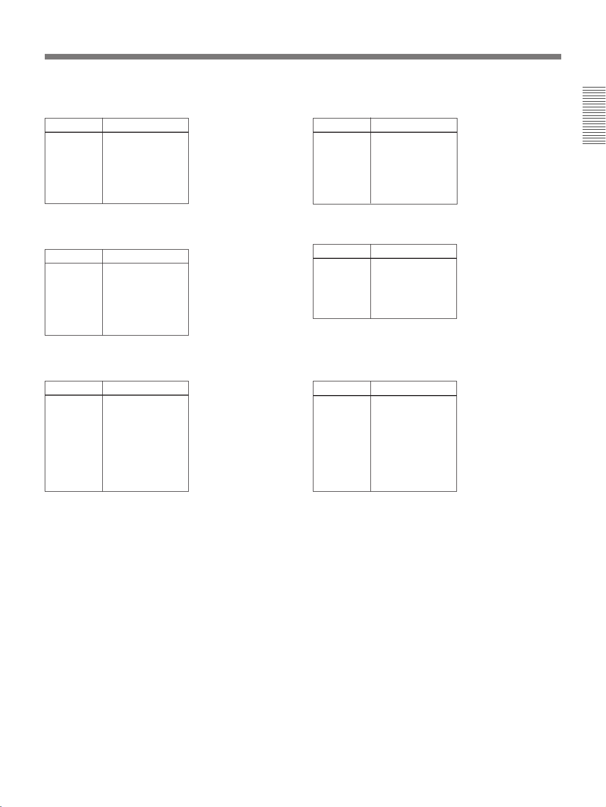
System Configuration
The tuner can be used with a Sony UHF synthesized
wireless microphone or UHF synthesized transmitter
among the models listed in the table below.
Sony 800 MHz-band system models
Overview
The WRR-801A is a reliable UHF synthesized
diversity tuner for the 800-MHz-band Sony UHF
wireless microphone system which uses the frequency
bands allocated for UHF TV broadcasting.
This tuner is designed to enable simultaneous use of
multiple channels when channels are selected
according to the Sony channel plan.
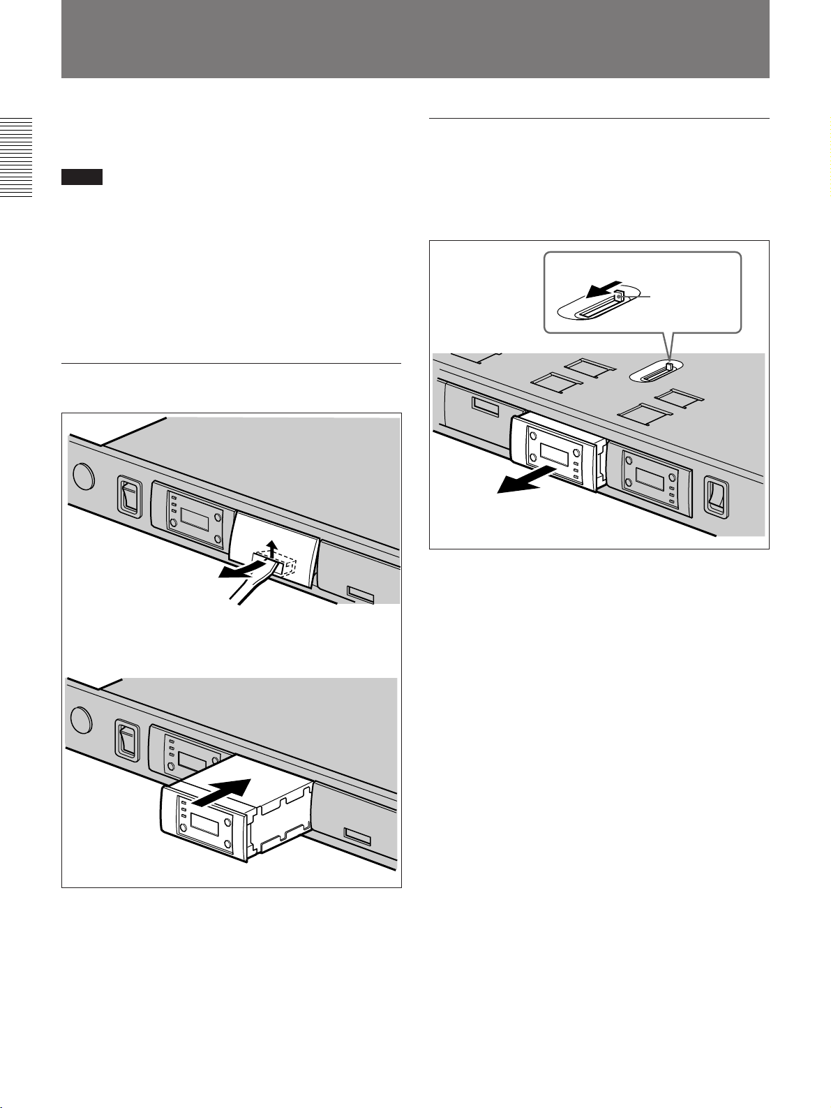
Installing six WRU-801A UHF Synthesized Tuner
Units will enable six-channel operation on the tuner.
At shipping, one tuner unit is installed in the tuner, and
additional tuner units (sold separately) can be installed
easilly.
Features
Phase Locked Loop (PLL) synthesized
system
The WRR-801A has a refined phase locked loop
(PLL) synthesizer circuit and covers two UHF TV
channels. It operates on 102 channels over a 14-MHz
frequency.
Preprogrammed wireless channel plan for
simultaneous multichannel operation
The WRR-801A has many preprogrammed, easily
settable channels for simultaneous multichannel
operation. One group allows setting of 102 channels.
The tuner also has 12 preset groups of channels, each
of which permits simultaneous operation of 5, 6, 8, 9
or 12 channels without the effects of intermodulation.
Modular multichannel reception
By installing optional WRU-801A UHF Synthesized
Tuner Units, you can receive up to six channels on one
WRR-801A unit.
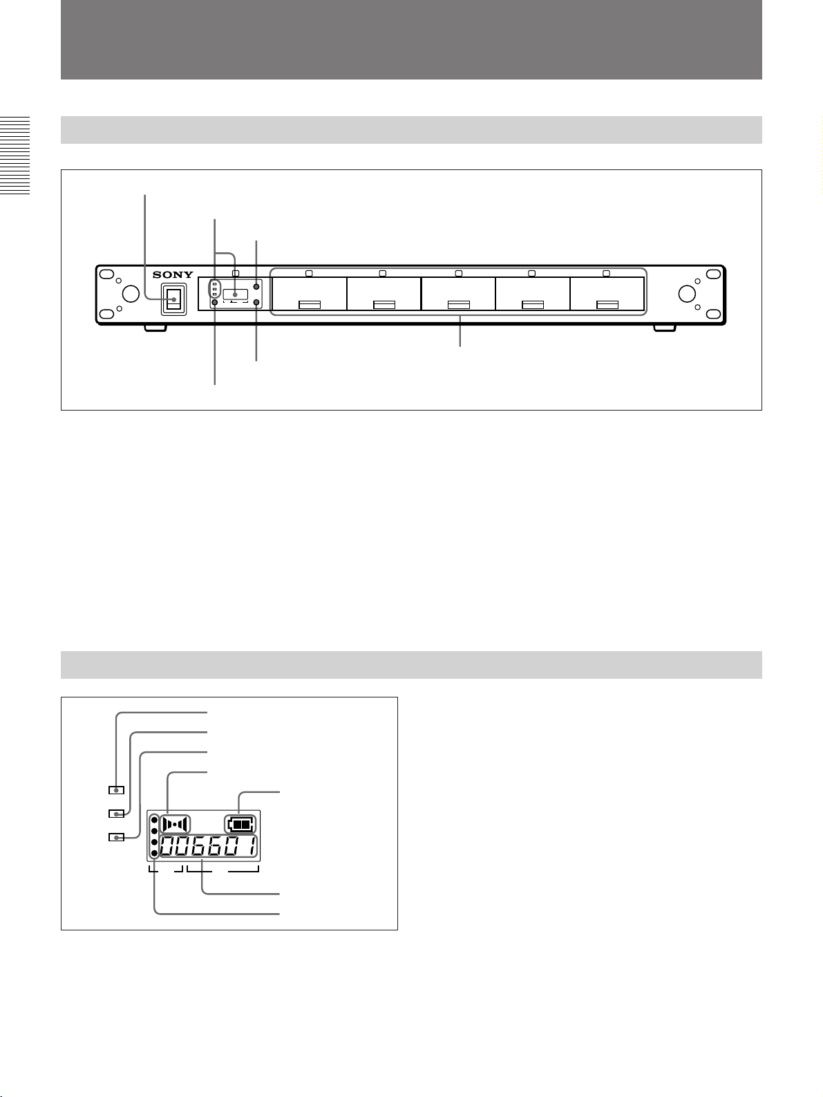
Versatile display
A liquid-crystal display provides a variety of
information, including the levels of the reception
channels, RF information and transmitter battery
condition.
792.250 to
798.500
Model name
WRR-800A (66)
WRR-801A (66)
WRR-810A (66)
WRR-820A (66)
WRR-840A (66)
WRR-850A (66)
WRR-860A (66)
Tuner
WRT-800A (66)
WRT-805A (66)
WRT-810A (66)
WRT-820A (66)
WRT-830A (66)
WRT-860A (66)
WRT-867A (66)
66
67
Frequency band
Frequency
(MHz)
TV channel Transmitter or
microphone
799.250 to
805.500