TABLE
OF
CONTENTS
Section
Title
Page
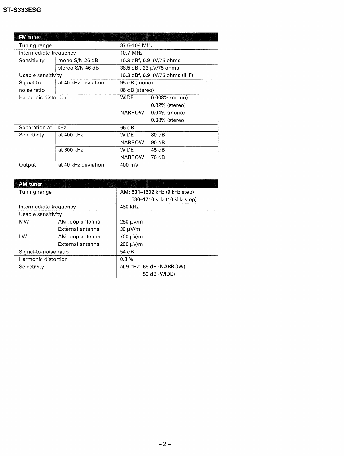
SPeCiFICATIONS
......
ee
eeeseeeeceeesesessneeeeenececceeueeteeeesssanenseeneenes
1
FEAtUIES
20...
ccccscccceccesssseecccceeseecersccaeenseeeesoceuessseesececaseesanareneaees
3
1.
GENERAL
1-1.
Location
and
Function
of
Controls
.......ceeeeeseeee
4
1-2.
Broadcast
ReECeption
............ccsseseeeeecceceesseeeceeesenenenee
5
1-2-1.
TUNING
IN
Manually
oo...
seseceseeeeeeererssessesseaees
5
1-2-2.
Tuning
in
Automatically
0.0...
ccceesssssssesseeeeeenees
5
1-2-3.
Storing
station
frequency
into
memory
..........+.
6
1-2-4.
Receiving
a
Stored
Station
...........cscceeeseesseeeeeeeees
6
1-2-5.
Scanning
Stored
Stations
Automatically
..........
7
1-2-6.
Scanning
Stored
Stations
Manually
...........
ee
7
2.
IC
PIN
FUNCTIONS
2-1.
10601
(uPD75108CW-A76)
Pin
Functions
..............
8
3.
BLOCK
DIAGRAM
.............:::ccccsessessereeesenesesseetennees
11
4.
ELECTRICAL
ADJUSTMENTS
................c:cssseseeeeee
13
5.
DIAGRAMS
5-1.
Printed
Wiring
Boards
.........eseeeseeesseesenenenees
17
5-2.
ScheMatic
DiaGram
........ceeesccssssesseessesesceseeeeeeeeeees
21
5-3.
IC
Block
Diagram
........
cece
eeeeseeeeseeseeneeseenenssnceeeeeees
24
5-4.
Semiconductor
Lead
Layouts
.......
ce
ccccssseeeeeeeee
26
6.
EXPLODED
VIEWS
6-1.
CABINET
ASSEMBLY
uu...
ec
ceessseeeeesesscseneeseones
27
6-1.
CHASSIS
ASSEMBLY
.........::cccsesssssereeneeeseenseeeeees
29
7.
ELECTRICAL
PARTS
LIST
..................::scssssesereneeees
31
|
ST-S333ESG
Precise
Tuning
with
the
large
knob
Features
The
detected
revolution
of
the
tuning
knob
is
under
digital-
contro!
so
that
you
can
tune
in
the
correct
frequency
and
stored
station
easily.
This
system
employs
a
variable
muting
function
that
adjusts
itself
to
the
rotation
speed
of
the
TUNING
knob
and
changes
the
muting
time.
This
function
realizes
a
feeling
which
is
very
close
to
that
of
an
analog
type
tuner.
Direct
comparator
technology
2
An
employed
PLL
IC
allows
the
comparison
frequency
to
be
as
high
as
the
channel
spacing
frequency,
thus
eliminating
the
tendency
of
a
low
comparison
frequency
to
slip
into
the
audio
range
and
degrade
the
signal-to-noise
ratio.
Free
from
digital
noise
:
When
thetuning
completes,
the
clock
oscillator
of
the
micro-
computer
stops.
Since
the
received
signal
passes
through
only
analog
circuits,
you
can
enjoy
the
pure
sound
without
an
interference.
NEW
Z-We)
oh
tien)
4-1
am
cc\yelaled
cere
bz
The
WOIS
(Wave
Optimized
IF
System)
which
makes
the
IF
waveform
optimum
shape
in
stereo
and
monaural
mode
and
the
WODD
(Wave
Optimized
Direct
Detector)
which
forms
the
VCO
oscillation
waveform
of
the
PLL
detector
ensure
low
distortion
sound.
Program
function
oe
.
Using
the
program
function,
you
can
automatically
tune
in
up
to
four
stations
which
have been
memorized
in
any
sequence
you
want.
Stations
will
be
received
one
by
one
as
the
power
is
turned
on
and
off
by
an
optional
audio
timer.
SAFETY-RELATED
COMPONENT
WARNING!!
COMPONENTS
IDENTIFIED
BY
MARK
/A\
OR
DOTTED
LINE
WITH
MARK
A\
ON
THE
SCHEMATIC
DIAGRAMS
AND
IN
THE
PARTS
LIST
ARE
CRITICAL
TO
SAFE
OPERATION.
REPLACE
THESE
COMPONENTS
WITH
SONY
PARTS
WHOSE
PART
NUMBERS
APPEAR
AS
SHOWN
IN
THIS
MANUAL
OR
IN
SUPPLEMENTS
PUBLISHED
BY
SONY.