Sony PS-DJ9000 - Stereo Turntable System User manual

1
SERVICE MANUAL
STEREO TURNTABLE SYSTEM
US Model
AEP Model
UK Model
E Model
PS-DJ9000
SPECIFICATIONS
Motor and Platter
Drive system Direct drive quartz
Motor 3 phase 8 pole Brushless DC motor
Platter Aluminum die-cast
Diameter 332 mm (13.1 inches)
Weight 750 g (1.85 lbs)
Speeds 33 and 45 rpm
1/3
Wow and flutter Less than 0.15 % (WRMS)
Signal to noise ratio More than 55 dB (DIN-B)
Tone Arm
Type Static balanced S-shaped tonearm with
detachable headshell
Effective arm length 230 mm
Overhang 15 mm
Usable cartridge weight 4 g (min.) to 10 g (max.)
General
Power requirements U.S.A. and Mexico: 120 V AC, 60 Hz
European countries: 220 - 230 V AC,
50/60 Hz
Other countries: 110 - 120 V/
220 - 240 V AC, 50/60 Hz
Power consumption 15 W
Dimensions Approx. 450 ×152 ×352 mm (17 ×
11/16
5 ×13 in) (w/h/d)
11/16 3/4
Mass 10 kg (22 lbs)
Supplied Accessories
Platter (2)
Slip mat (2)
Dust cover (with hinges) (2)
Counterweight (2)
Cartridge and headshell (2)
45 adaptor (2)
Audio cord (with ground wire) (2)
AC power cord (2)
Design and specifications are subject to change without
notice.
Replacing the Cartridge
The life expectancy of the stylus tip is about 500 hours.
To maintain optimum sound quality and prevent
damage to your records, we recommend replacing the
cartridge before the end of this time duration.
Obtain a replacement cartridge from your Sony dealer.
This set is the stereo turntable in
PMPK-DJ9000.
9-929-553-12
2001F0200-1
© 2001.6
Sony Corporation
Home Audio Company
Shinagawa Tec Service Manual Production Group
Ver 1.12001. 06

2
SAFETY-RELATED COMPONENT WARNING!!
COMPONENTS IDENTIFIED BY MARK 0OR DOTTED LINEWITH
MARK 0ON THE SCHEMATIC DIAGRAMS AND INTHE PARTS
LIST ARE CRITICAL TO SAFE OPERATION. REPLACE THESE
COMPONENTSWITH SONYPARTSWHOSE PARTNUMBERS AP-
PEAR AS SHOWN INTHIS MANUAL OR IN SUPPLEMENTS PUB-
LISHED BY SONY.
SAFETY CHECK-OUT
After correcting the original service problem, perform the follow-
ing safety checks before releasing the set to the customer:
Check the antenna terminals, metal trim, “metallized” knobs,
screws, and all other exposed metal parts for AC leakage.
Check leakage as described below.
LEAKAGETEST
The AC leakage from any exposed metal part to earth ground and
from all exposed metal parts to any exposed metal part having a
return to chassis, must not exceed 0.5 mA (500 microampers).
Leakage current can be measured by any one of three methods.
1. A commercial leakage tester, such as the Simpson 229 or RCA
WT-540A. Follow the manufacturers’ instructions to use these
instruments.
2. A battery-operated AC milliammeter. The Data Precision 245
digital multimeter is suitable for this job.
3. Measuring the voltage drop across a resistor by means of a VOM
or battery-operated AC voltmeter. The “limit” indication is 0.75
V, so analog meters must have an accurate low-voltage scale.
The Simpson 250 and Sanwa SH-63Trd are examples of a pas-
sive VOM that is suitable. Nearly all battery operated digital
multimeters that have a 2V AC range are suitable. (See Fig. A)
Fig. A. Using an AC voltmeter to check AC leakage.
0.15µF
To Exposed Metal
Parts on Set
1.5kΩ
AC
voltmeter
(0.75V)
Earth Ground
TABLE OF CONTENTS
1. GENERAL ..................................................................... 3
2. DIAGRAMS
2-1. Circuit boards Location ...................................................... 5
2-2. Schematic Diagram – Main Section – ................................ 6
2-3. Schematic Diagram – Motor Section – .............................. 7
2-4. Printed Wiring Board – Main Section – ............................. 8
2-5. Printed Wiring Board – Power Section – ........................... 9
2-6. Printed Wiring Board – Motor Section –.......................... 10
3. EXPLODED VIEWS
3-1. Bottom Section ................................................................. 11
3-2. Cabinet Section ................................................................. 12
4. ELECTRICAL PARTS LIST .................................... 13

3
SECTION 1
GENERAL
1POWER ON/OFF switch
2Spindle
3Strobo lamp
4START/STOP button
5Slip mat
6Platter
7TARGET LIGHT and release button
The TARGET LIGHT allows you to see the
position of the stylus in the dark. Push and
depress the TARGET LIGHT to turn it off.
Push the release button to raise the light again
and turn it on.
8Cartridge and headshell
9Finger lift
q; PITCH BEND + and – buttons
qa Insulator
qs Dust cover
qd Headshell holder
qf Counter weight
qg Hinge
qh 45 adaptor
qj height adj (adjusting) lever
Use this lever to adjust the vertical position of the
tonearm (wd).
qk LOCK lever (for height adjustment)
ql ANTI-SKATING dial
w; Cueing lever
wa Arm stand
ws Speed-adjustment hole
This hole is for use by qualified service
technicians only.
wd Tonearm
wf PITCH ADJ. (adjusting) knob
wg QUARTZ lock button
wh SPEED (33/45) button
wj Locking ring
1
qs
qd
qf
qg
qh
qj
qk
ql
w;
wa
ws
wd
wf
wg
wh
wj
2
3
4
5
6
7
8
9
0
qa
This section is extracted from
instruction manual.

4
Assembling the Turntable
3
4
5
1
2
1
Carefully place the platter onto the spindle.
Make sure the two pins on the bottom of the
platter are properly inserted into the two holes in
the motor, as indicated by the arrows in the
illustration above.
2
Place the slip mat on the platter.
3
Slide the counterweight onto the shaft at the rear
of the tonearm and turn 3 or 4 times in the
direction of the arrow.
4
Insert the headshell into the end of the tonearm.
Turn the locking ring in the direction of the arrow
until the headshell is secure.
5
Insert the hinges on the dust cover into the hinge
pockets on the rear of the cabinet.
6
Getting Started
Adjusting the Turntable
Before attempting to play any records, be sure to
complete the following steps to properly adjust the
tonearm balance, tracking force and anti-skating dial.
Failure to complete these adjustments will result in
inferior sound quality and may cause permanent
damage to the stylus and record.
1
Make sure the turntable is level.
2
Set ANTI-SKATING to “0.”
0
1
2
3
4
5
6
7
A
N
T
I
-
S
K
A
T
I
N
G
3
Set the cueing lever to the down position.
4
Turn up the protective cover to expose the stylus,
and move the tonearm to the space between the
arm stand and the platter.
Take care not to damage the stylus.
5
Balance the tonearm by turning the counterweight
either clockwise or counterclockwise.
When the tonearm is properly balanced
It will remain level with the platter when released.
It should not tilt in the direction of either the headshell
or the counterweight.
6
Return the tonearm to the arm stand.
7
A properly balanced tonearm has a tracking force
of zero. Therefore, rotate the tracking force scale
ring until “0”is aligned to the index line.
Restrain the counterweight with your other hand so
that it does not rotate along with the scale ring.
0
Index line
8
When you use the supplied cartridge, turn the
counterweight counterclockwise one full rotation,
and then continue turning it until the index line
comes to 1. Since one full rotation of the
counterweight yields a tracking force of 3 grams,
this adjustment results in a tracking force of
4 grams, which is the normal requirement for the
supplied cartridge.
You can set a tracking force of 3 to 7 grams.
1
When optionally available cartridge is used
The tracking force scale ring is marked in 0.1-gram
units. One full rotation yields a tracking force of
3 grams.
9
Set ANTI-SKATING to the same value as the
tracking force scale ring.
The numbers on the ANTI-SKATING dial indicate
the number of grams in tracking force.
Turn this ring so that the
“0“ lines up with the index
line.
Turn the counterweight
counterclockwise one full
rotation, and then a little
more until the index line
is aligned to 1.

55
SECTION 2
DIAGRAMS
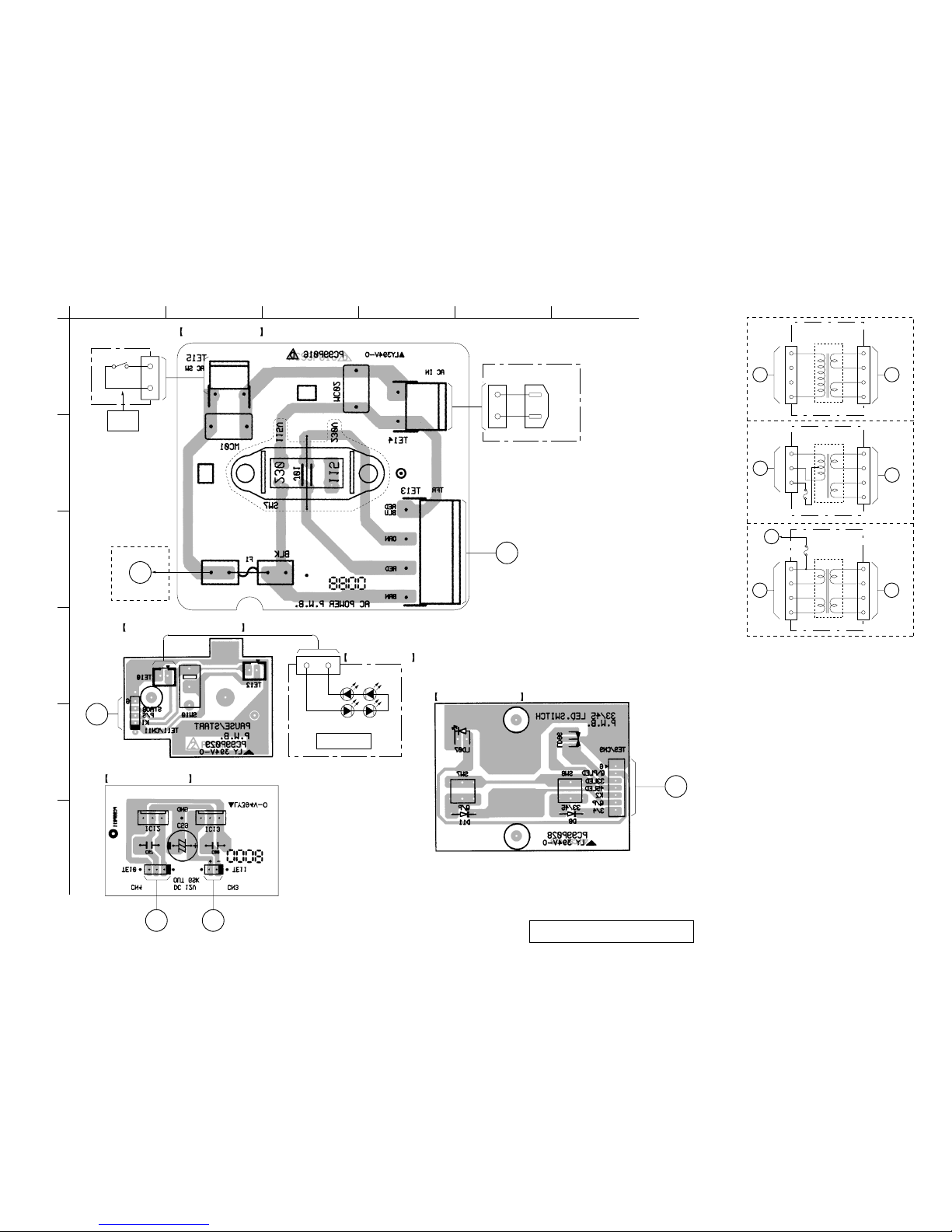
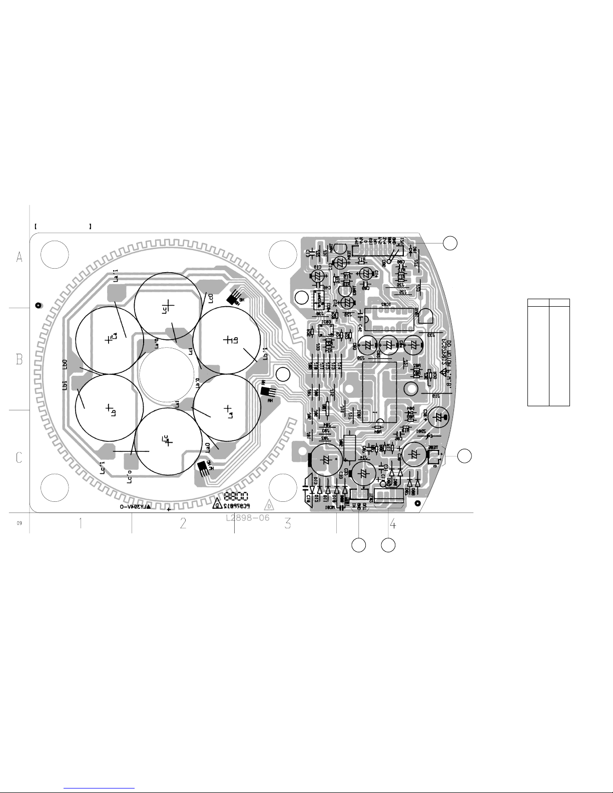
Note on PrintedWiring Board:
•X: parts extracted from the component side.
•Y: parts extracted from the conductor side.
•b: Pattern from the side which enables seeing.
Note on Schematic Diagram:
• All capacitors are in µF unless otherwise noted. pF: µµF
50 WV or less are not indicated except for electrolytics
and tantalums.
• All resistors are in Ωand 1/4W or less unless otherwise
specified.
•C: panel designation.
•U: B+ Line.
•V: B– Line.
• Voltages are dc with respect to ground under no-signal
conditions.
no mark : Power on
• Voltages are taken withaVOM (Input impedance 10MΩ).
Voltage variations may be noted due to normal produc-
tion tolerances.
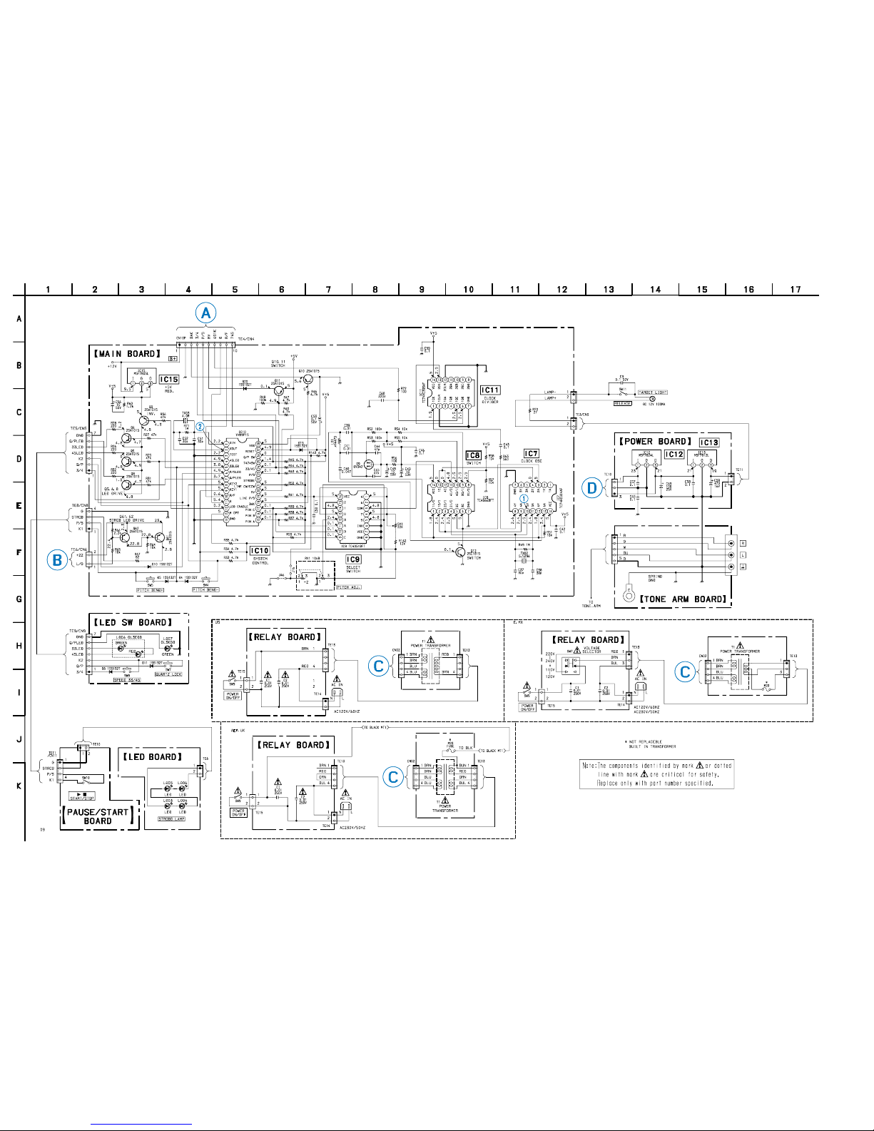
2-1. Circuit Boards Location
Note: The components identified by mark 0or dotted line
with mark 0are critical for safety.
Replace only with part number specified.
NOTE FOR PRINTED WIRING BOARD AND SCHEMATIC DIAGRAM
7
OperationsOperations
5
Remove the protective cover from the cartridge
and release the arm stopper.
6
Set the cueing lever in the up position.
Move the tonearm to the desired point on the
record.
7
Set the cueing lever to the down position.
The tonearm will descend slowly to the record and
play will begin.
8
If you want to change the pitch, press the
QUARTZ lock button (the QUARTZ indicator will
turn off). Then adjust the pitch by moving the
PITCH ADJ. knob.
The distance from the center position to the
farthest point on the scale represents a change of
10% in the pitch. You can also use the
PITCH BEND + and – buttons to change the pitch
(see “Using the PITCH BEND + and – buttons” on
page 8).
9
If you wish, you can return to normal speed
(33 1/3 or 45 rpm) while the PITCH ADJ. knob is
off center by pressing the QUARTZ lock button
(the QUARTZ indicator will turn on).
Press the QUARTZ lock button again to go back to
the previous pitch setting (the QUARTZ indicator
will turn off).
Note
The PITCH ADJ. knob does not function while the
QUARTZ lock is on (i.e., while the QUARTZ indicator is
on).
10
To adjust the volume, use the respective channel
fader on the mixer, or the volume control on the
stereo component system or amplifier.
To stop play
1Set the cueing lever in the up position and return
the tonearm to the arm stand.
Attach the protective cover onto the cartridge to
prevent damage to the stylus.
2Press Bx START/STOP.
The platter stops rotating.
Secure the tonearm with the arm stopper.
3Turn POWER to OFF.
To pause play
Press Bx START/STOP or set the cueing lever in the
up position to raise the stylus.
Playing a Record
5
8
6
3,8,9
5
8,9
6,7
1
4
2
3
Before playing a record, be sure the PHONO/LINE
switch on the mixer is set to PHONO.
1
Place a record on the platter.
Note
Place only one record on the platter at a time. If two or
more records are stacked on the platter, the stylus will
not make proper contact with the grooves and the
quality of reproduction will be impaired.
2
Turn the POWER switch to ON.
The strobo lamp, the QUARTZ lock indicator, and
SPEED indicator light up.
Turn the POWER switch on the mixer and
amplifier to ON also.
3
Set PITCH ADJ. knob to the center position.
When the turntable is turned on, the platter speed
is automatically set to 33 rpm. Verify that the
green indicator lights up.
4
Press Bx START/STOP.
The platter starts rotating.
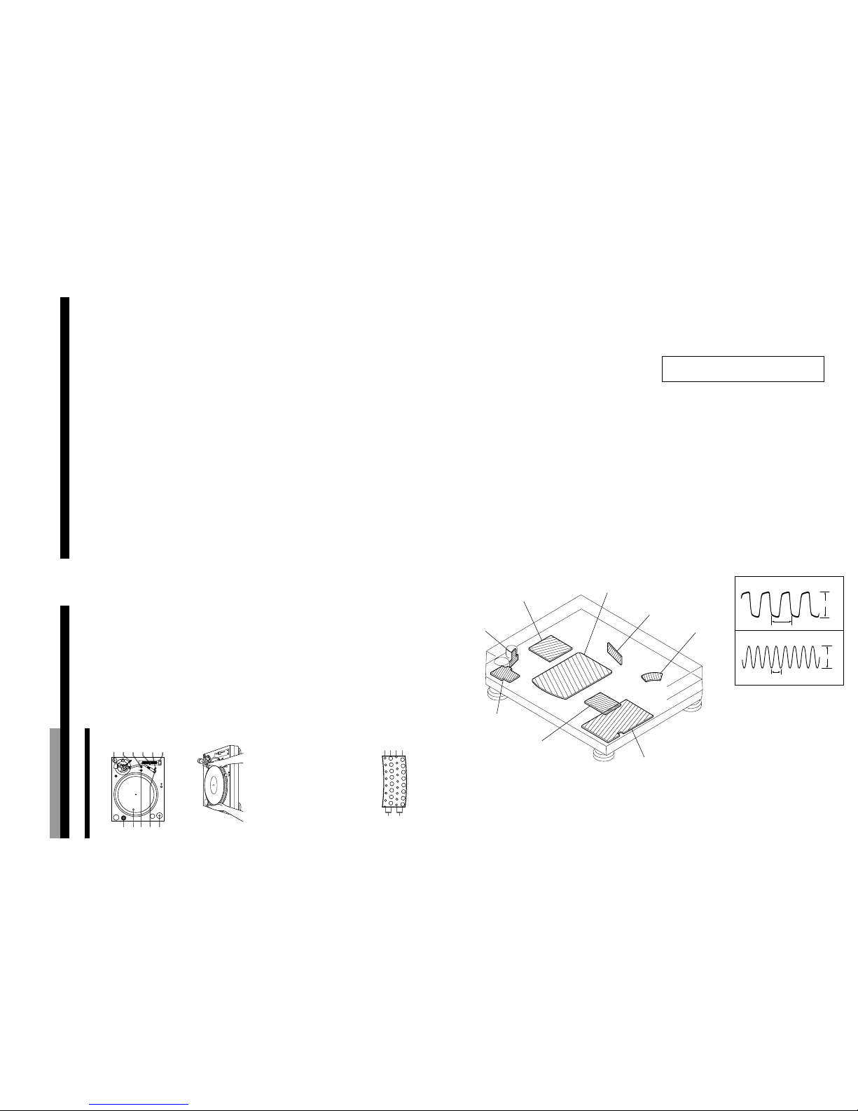
If you select 33 rpm when the turntable is
connected to a 50 Hz power source, the uppermost
row of the strobe dots should appear to stand still.
33
45
45
33
50 Hz
60 Hz
(Continued)
8
Operations
To play an another part of the record
1Set the cueing lever to the up position to raise the
stylus.
2Move the tonearm to the desired position.
3Set the cueing lever to the down position.
To play a 45 single
Place the supplied 45 adaptor onto the spindle.
Press SPEED to select 45 rpm.
The green indicator changes to red.
After you have finished using the adaptor, return it to
the adaptor tray.
Using the PITCH BEND + and – buttons
You can use the PITCH BEND + and –buttons to
synchronize the beat of the selection playing on one
turntable with the beat of another selection playing on
the other turntable. You can use these buttons even if
the QUARTZ lock button is turned on or off.
1Use the PITCH ADJ. knob to synchronize the
speed of the selection playing on one of the
turntables with the speed of the selection on the
other turntable.
2Press the PITCH BEND + and –buttons to
synchronize the beat of both selections. Pressing
and holding down the + or –button causes the
selection to play 10% faster or slower than the
normal playing speed.
z
If the strobe dots are not stationary when the PITCH
ADJ. knob is set to the center position
Adjust the platter speed by sliding the PITCH ADJ.
knob toward + or –until the strobe dots become
stationary.
z
If you have an extra headshell, keep it in the
headshell holder.
POWER board
TONE ARM boar
d
MAIN board
LED SW board
PAUSE/START board
LED board
RELAY board MOTOR board
1IC7 0
2IC10 2(XOUT)
3.5Vp-p
5Vp-p
180msec
250msec
• WAVEFORMS
– MAIN SECTION –

66
PS-DJ9000
2-2. SCHEMATIC DIAGRAM – MAIN SECTION – • See Page 8 and 9 for PrintedWiring Boards.
(Page 7)
(Page 7)
(Page 7)
(Page 7)
(Page 7)
(Page 7)
SLIDE SW
L003, L004, L005, L006:
Exchange all the four when even this one diode breaks in either one.

77
PS-DJ9000
(Page 6)
(Page 6)
(Page 6)
(Page 6)
2-3. SCHEMATIC DIAGRAM – MOTOR SECTION – • See Page 10 for PrintedWiring Boards.

88
PS-DJ9000
2-4. PRINTEDWIRING BOARD – MAIN SECTION – • See Page 5 for Circut Boards Location. • See Page 6 for Schematic Diagram.
There are a few cases that the part isn’t mounted in
model is printed on diagram.
D4 B-2
D5 B-2
D9 C-8
D10 B-6
D19 A-5
D20 D-5
IC7 D-7
IC8 D-8
IC9 B-7
IC10 B-5
IC11 E-8
IC15 D-4
Q5 C-5
Q6 D-5
Q8 D-5
Q9 D-5
Q10 C-5
Q11 D-5
Q12 D-7
Q61 D-3
Q62 D-3
• Semiconductor
Location
Ref.No. Location
114
14 8
17
71
14 8
71
14 8
71
14 8
71
14 8
28 15
K
K
A
E
17
110
EE
E
E
E
E
E
E
41 12
IGO
MAIN BOARD
A F E
B
G
TARGET
LIGHT
RELEASE
SW11
(Page 10)(Page 9) (Page 10) (Page 9) (Page 9)
12345678
A
B
C
D
E
9

99
PS-DJ9000
E,MX
4
ACIN
N
L
POWER
ON/OFF
AEP, UK
SW9
RELAY BOARD
5
LED SW BOARD
F
(Page 8)
G
LD03
STROBO LAMP
LD04
LD05LD06
PAUSE/START BOARD
LED BOARD
(Page 8)
D E
POWER BOARD
(Page 10) (Page 8)
09
5
4 C
4C
4 C
POWER
TRANSFORMER
POWER
TRANSFORMER
US
E, MX
(Page 10)
(Page 10)
(Page 10)
AEP, UK
POWER
TRANSFORMER
NOT REPLACEBLE:
BUILT IN TRANSFORMER
*
*
*
2-5. PRINTEDWIRING BOARD –POWER SECTION –•See Page 5 for Circut Boards Location. •See Page 6 for Schematic Diagram.
There are a few cases that the part isn’t mounted in
model is printed on diagram.
123456
A
B
C
D
E
F

10 10
PS-DJ9000
D1 A-4
D4 B-4
D5 C-4
D6 C-4
D7 C-4
D8 C-4
D9 C-4
D10 C-4
D11 C-3
D12 C-3
D13 C-3
ZD1 C-4
IC1 B-4
IC3 B-3
IC4 A-3
Q3 A-4
Q4 A-4
•Semiconductor
Location
Ref.No. Location
MOTOR BOARD
CD
A
B(Page 8)
(Page 8)
(Page 9) (Page 9)
2-6. PRINTED WIRING BOARD –MOTOR SECTION –•See Page 5 for Circut Boards Location. •See Page 7 for Schematic Diagram.

11
3-1. BOTTOM SECTION
SECTION 3
EXPLODEDVIEW
The components identified by
mark 0or dotted line with mark
0are critical for safety.
Replace only with part number
specified.
• Items marked “*” are not stocked since they
are seldom required for routine service. Some
delay should be anticipated when ordering
these items.
• The mechanical parts with no reference num-
ber in the exploded views are not supplied.
• Accessories and packing materials are given
in the last of the electrical parts list.
NOTE:
• -XX and -X mean standardized parts, so they
may have some difference from the original
one.
• Color Indication of Appearance Parts
Example:
KNOB, BALANCE (WHITE) . . . (RED)
↑↑
Parts Color Cabinet's Color
Ref. No. Part No. Description Remark Ref. No. Part No. Description Remark
1 4-231-219-01 PLATE(ALUMINUM)
2 4-231-226-01 COVER, DUST
3 4-231-225-01 RUBBER (DUST COVER)
4 4-231-216-01 MAT
5 4-231-238-01 PLATE ASSY, ALUMINUM
6 4-231-235-01 HINGE ASSY
7 4-231-209-01 PLASTIC, HINGE
8 7-685-648-79 SCREW +P3x12 TYPE2 SLIT
9 4-231-237-01 FOOT ASSY
10 7-685-651-79 SCREW +P3x20 TYPE2 SLIT
1
2
3
3
4
5
678
678
not supplied
9
9
10 10 10 10

12
51
55
53
54
56
57
58
59
60
61
62
63
64
65
66 67
67
67
68
68
69
69
69
69
69
69
69
69
69
69
69
70
72
72
73
not supplied
(POWER board)
not supplied
(MAIN board)
not supplied
(LED SW board)
not supplied
not supplied
(PAUSE/START
board)
not supplied
(RELAY board)
not
supplied
supplied with
57
not
supplied
not
supplied
not
supplied
3-2. CABINET SECTION
51 A-4412-592-A MOTOR BOARD, COMPLETE
53 4-231-231-01 TERGET (LIGHT) ASSY
54 4-231-232-01 BASE ASSY, KNOB (AEP,UK)
54 4-232-018-01 BASE ASSY, KNOB (US,MX,E)
56 4-231-230-01 ARM ASSY, TONE
57 1-251-931-11 CARTRIDGE (INCLUDING STYLUS)
58 4-231-511-01 SHELL ASSY, HEAD
59 4-231-239-01 WEIGHT ASSY, COUNTER
60 4-231-233-01 BASE ASSY, TONE ARM
61 4-231-228-01 KNOB
62 4-231-234-01 SOCKET ASSY, AC
63 4-231-213-01 KNOB, VR (AEP,UK)
63 4-232-017-01 KNOB, VR (US,MX,E)
64 4-231-214-01 PLATE, VR NAME
65 4-231-215-01 KNOB, QUARTZ
66 4-231-212-01 KNOB, P/B (AEP,UK)
66 4-232-016-01 KNOB, P/B (US,MX,E)
67 4-231-224-01 SPRING
68 3-703-136-11 SCREW, TAPPING
69 7-685-647-79 SCREW +P3x10 TYPE2 SLIT
70 7-685-903-31 SCREW +PTPWH3x10 (TYPE2)
72 7-682-162-01 SCREW +P4x10
73 4-231-223-01 BRACKET (POWER SW)
74 4-234-872-01 45 ADAPTOR
T1 1-435-743-11 TRANSFORMER, POWER (US,MX)
T1 1-435-744-11 TRANSFORMER, POWER (AEP,UK)
T1 1-435-745-11 TRANSFORMER, POWER (E)
Ref. No. Part No. Description Remark Ref. No. Part No. Description Remark
Ver 1.1 2001.06
74

13
SECTION 4
ELECTRICAL PARTS LIST
Ref. No. Part No. Description Remark Ref. No. Part No. Description Remark
NOTE:
• Due to standardization, replacements in the
parts list may be different from the parts speci-
fied in the diagrams or the components used
on the set.
• -XX and -X mean standardized parts, so they
may have some difference from the original
one.
• RESISTORS
All resistors are in ohms.
METAL: Metal-film resistor.
METAL OXIDE: Metal oxide-film resistor.
F: nonflammable
• Items marked “*” are not stocked since they
are seldom required for routine service.
Some delay should be anticipated when order-
ing these items.
• SEMICONDUCTORS
In each case, u: µ, for example:
uA. . : µA. . uPA. . : µPA. .
uPB. . : µPB. . uPC. . : µPC. .
uPD. . : µPD. .
• CAPACITORS
uF: µF
• COILS
uH: µH
The components identified by
mark 0or dotted line with mark
0are critical for safety.
Replace only with part number
specified.
When indicating parts by reference
number, please include the board.
LED BOARD
**********
LD3 8-719-301-38 DIODE SEL2210S-C
LD4 8-719-301-38 DIODE SEL2210S-C
LD5 8-719-301-38 DIODE SEL2210S-C
LD6 8-719-301-38 DIODE SEL2210S-C
**************************************************************
LED SW BOARD
*************
< DIODE >
D8 8-719-107-94 DIODE 1SS132T-73
D11 8-719-107-94 DIODE 1SS132T-73
LD06 8-719-981-49 DIODE GL3ED8 (SPEED 33/45)
LD07 8-719-988-04 DIODE GL3KG8 (QUARTZ LOCK)
< SWITCH >
SW7 1-553-856-00 SWITCH, KEY BOARD (QUARTZ LOCK)
SW8 1-553-856-00 SWITCH, KEY BOARD (SPEED 33/45)
**************************************************************
MAIN BOARD
***********
< CAPACITOR >
C37 1-162-210-31 CERAMIC 30PF 5% 50V
C38 1-162-210-31 CERAMIC 30PF 5% 50V
C39 1-162-306-11 CERAMIC 0.01uF 20.00% 16V
C40 1-164-206-41 CERAMIC 0.047uF 99% 50V
C41 1-162-306-11 CERAMIC 0.01uF 20.00% 16V
C42 1-136-165-00 FILM 0.1uF 5.00% 50V
C43 1-136-165-00 FILM 0.1uF 5.00% 50V
C44 1-162-215-31 CERAMIC 47PF 5% 50V
C45 1-162-215-31 CERAMIC 47PF 5% 50V
C46 1-136-165-00 FILM 0.1uF 5.00% 50V
C48 1-126-964-11 ELECT 10uF 20.00% 50V
C49 1-126-964-11 ELECT 10uF 20.00% 50V
C50 1-136-165-00 FILM 0.1uF 5.00% 50V
C51 1-162-210-31 CERAMIC 30PF 5% 50V
C52 1-162-210-31 CERAMIC 30PF 5% 50V
C53 1-126-956-11 ELECT 0.1uF 20.00% 50V
C56 1-126-964-11 ELECT 10uF 20.00% 50V
C59 1-136-165-00 FILM 0.1uF 5.00% 50V
C60 1-162-286-31 CERAMIC 220PF 10% 50V
< DIODE >
D4 8-719-107-94 DIODE 1SS132T-73
D5 8-719-107-94 DIODE 1SS132T-73
D9 8-719-979-71 DIODE SVC342-L
D10 8-719-107-94 DIODE 1SS132T-73
D19 8-719-107-94 DIODE 1SS132T-73
D20 8-719-107-94 DIODE 1SS132T-73
< IC >
IC7 8-759-233-64 IC TC74HCU04AF-TP1
IC8 8-759-530-28 IC TC4066BFT(EL,N)
IC9 8-759-009-05 IC TC4051BFT(EL,N)
IC10 8-759-832-40 IC TC9915
IC11 8-759-233-26 IC TC74HC393AF-TP1
IC15 8-759-231-53 IC M5F7805L
< TRANSISTOR >
Q5 8-729-201-53 TRANSISTOR 2SA1015-YGR
Q6 8-729-201-53 TRANSISTOR 2SA1015-YGR
Q8 8-729-201-53 TRANSISTOR 2SA1015-YGR
Q9 8-729-201-53 TRANSISTOR 2SA1015-YGR
Q10 8-729-201-53 TRANSISTOR 2SA1015-YGR
Q11 8-729-201-53 TRANSISTOR 2SA1015-YGR
Q12 8-729-119-78 TRANSISTOR 2SC1815-YGR
Q61 8-729-201-53 TRANSISTOR 2SA1015-YGR
Q62 8-729-201-53 TRANSISTOR 2SA1015-YGR
< RESISTOR >
R25 1-247-871-11 CARBON 47K 5% 1/4W
R26 1-249-409-11 CARBON 220 5% 1/4W F
R27 1-247-871-11 CARBON 47K 5% 1/4W
R28 1-249-409-11 CARBON 220 5% 1/4W F
R31 1-247-871-11 CARBON 47K 5% 1/4W
R32 1-249-409-11 CARBON 220 5% 1/4W F
R33 1-247-847-11 CARBON 4.7K 5% 1/4W
R34 1-247-847-11 CARBON 4.7K 5% 1/4W
R36 1-247-871-11 CARBON 47K 5% 1/4W
R37 1-247-847-11 CARBON 4.7K 5% 1/4W
R38 1-247-847-11 CARBON 4.7K 5% 1/4W
R39 1-247-847-11 CARBON 4.7K 5% 1/4W
R40 1-247-847-11 CARBON 4.7K 5% 1/4W
R41 1-247-847-11 CARBON 4.7K 5% 1/4W
R43 1-247-847-11 CARBON 4.7K 5% 1/4W
MAINLED SW
• Abbreviation
MX:Mexican Model
LED
L003, L004, L005, L006:
Exchange all the four when even this one diode breaks in either one.

Ref. No. Part No. Description Remark Ref. No. Part No. Description Remark
14
R44 1-247-847-11 CARBON 4.7K 5% 1/4W
R45 1-247-847-11 CARBON 4.7K 5% 1/4W
R46 1-247-847-11 CARBON 4.7K 5% 1/4W
R47 1-247-847-11 CARBON 4.7K 5% 1/4W
R48 1-247-879-11 CARBON 100K 5% 1/4W
R49 1-247-903-00 CARBON 1M 5% 1/4W
R50 1-247-847-11 CARBON 4.7K 5% 1/4W
R51 1-249-432-11 CARBON 18K 5% 1/4W
R52 1-247-879-11 CARBON 100K 5% 1/4W
R53 1-247-879-11 CARBON 100K 5% 1/4W
R54 1-247-855-11 CARBON 10K 5% 1/4W
R55 1-247-855-11 CARBON 10K 5% 1/4W
R56 1-247-807-11 CARBON 100 5% 1/4W
R57 1-247-855-11 CARBON 10K 5% 1/4W
R58 1-247-855-11 CARBON 10K 5% 1/4W
R59 1-247-847-11 CARBON 4.7K 5% 1/4W
R60 1-247-855-11 CARBON 10K 5% 1/4W
R63 1-247-825-11 CARBON 560 5% 1/4W
R64 1-247-855-11 CARBON 10K 5% 1/4W
R65 1-247-855-11 CARBON 10K 5% 1/4W
R66 1-247-839-11 CARBON 2.2K 5% 1/4W
R67 1-249-404-00 CARBON 82 5% 1/4W F
R70 1-247-693-11 CARBON 27 5% 1/4W F
R71 1-247-903-00 CARBON 1M 5% 1/4W
R72 1-247-807-11 CARBON 100 5% 1/4W
R162 1-249-430-11 CARBON 12K 5% 1/4W
R163 1-247-847-11 CARBON 4.7K 5% 1/4W
< VARIABLE RESISTOR >
RV1 1-227-359-11 RES, VAR (SLIDE) 10K
SV1 1-241-765-11 RES, ADJ, CARBON 22K
< SWITCH >
SW4 1-553-856-00 SWITCH, KEY BOARD (PITCH BEND – )
SW5 1-553-856-00 SWITCH, KEY BOARD (PITCH BEND + )
< VIBRATOR >
TX02 1-795-150-11 VIBRATOR CRYSTAL (5.5296MHz)
TX03 1-795-151-11 VIBRATOR CRYSTAL (4MHz)
**************************************************************
A-4412-592-A MOTOR BOARD, COMPLETE
***********************
< CAPACITOR >
C2 1-126-940-11 ELECT 330uF 20.00% 25V
C3 1-126-940-11 ELECT 330uF 20.00% 25V
C4 1-126-940-11 ELECT 330uF 20.00% 25V
C5 1-101-006-99 CERAMIC 0.047uF 50V
C6 1-164-159-11 CERAMIC 0.1uF 50V
C7 1-101-004-00 CERAMIC 0.01uF 50V
C8 1-101-004-00 CERAMIC 0.01uF 50V
C9 1-101-002-00 CERAMIC 0.0022uF
C10 1-164-159-11 CERAMIC 0.1uF 50V
C11 1-101-004-00 CERAMIC 0.01uF 50V
C12 1-126-959-11 ELECT 0.47uF 25V
C13 1-101-006-99 CERAMIC 0.047uF 50V
C14 1-126-963-11 ELECT 4.7uF 50V
C15 1-126-964-11 ELECT 10uF 20.00% 50V
C19 1-126-964-11 ELECT 10uF 20.00% 50V
C20 1-126-768-11 ELECT 2200uF 20.00% 16V
C30 1-126-942-11 ELECT 1000uF 20.00% 25V
C31 1-164-159-11 CERAMIC 0.1uF 50V
C32 1-126-942-11 ELECT 1000uF 20.00% 25V
C33 1-126-952-11 ELECT 1000uF 20.00% 35V
C45 1-164-159-11 CERAMIC 0.1uF 50V
C48 1-164-159-11 CERAMIC 0.1uF 50V
< DIODE >
D1 8-719-107-94 DIODE 1SS132
D4 8-719-107-94 DIODE 1SS132
D5 8-719-200-02 DIODE 1N4002
D6 8-719-200-02 DIODE 1N4002
D7 8-719-200-02 DIODE 1N4002
D8 8-719-200-02 DIODE 1N4002
D9 8-719-200-02 DIODE 1N4002
D10 8-719-200-02 DIODE 1N4002
D11 8-719-200-02 DIODE 1N4002
D12 8-719-200-02 DIODE 1N4002
D13 8-719-200-02 DIODE 1N4002
DZ1 8-719-109-89 DIODE HZ5.6EB2
< IC >
IC1 8-759-202-02 IC TA7259P
IC2 8-759-832-39 IC IC9242P
IC3 8-759-510-72 IC BA10393F-E1
IC4 8-759-032-81 IC TC74HC74AP
< TRANSISTOR >
Q3 8-729-281-53 TRANSISTOR 2SC536-2F
Q4 8-729-281-53 TRANSISTOR 2SC536-2F
< RESISTOR >
R2 1-247-852-11 CARBON 7.5K 5% 1/4W
R3 1-247-852-11 CARBON 7.5K 5% 1/4W
R5 1-216-356-00
METAL OXIDE FILM
3.9 5% 1/4W
R6 1-247-883-00 CARBON 150K 5% 1/4W
R7 1-247-879-11 CARBON 100K 5% 1/4W
R9 1-247-879-11 CARBON 100K 5% 1/4W
R10 1-247-883-00 CARBON 150K 5% 1/4W
R11 1-247-857-11 CARBON 12K 5% 1/4W
R12 1-247-847-11 CARBON 4.7K 5% 1/4W
R13 1-247-847-11 CARBON 4.7K 5% 1/4W
R16 1-247-868-11 CARBON 36K 5% 1/4W
R17 1-247-855-11 CARBON 10K 5% 1/4W
R18 1-247-887-00 CARBON 220K 5% 1/4W
R19 1-247-883-00 CARBON 150K 5% 1/4W
R20 1-247-855-11 CARBON 10K 5% 1/4W
R21 1-247-847-11 CARBON 4.7K 5% 1/4W
R22 1-247-903-00 CARBON 1M 5% 1/4W
R23 1-247-903-00 CARBON 1M 5% 1/4W
R24 1-247-847-11 CARBON 4.7K 5% 1/4W
R25 1-247-855-11 CARBON 10K 5% 1/4W
R39 1-247-855-11 CARBON 10K 5% 1/4W
< VARIABLE RESISTOR >
SV1 1-241-765-11
RES, ADJ, CARBON
22K
**************************************************************
MAIN MOTOR

Ref. No. Part No. Description Remark Ref. No. Part No. Description Remark
15
PAUSE/START BOARD
******************
<SWITCH>
SW10 1-570-245-11 SWITCH, MICRO (Bx START STOP)
**************************************************************
POWER BOARD
*************
< CAPACITOR >
C57 1-164-159-11 CERAMIC 0.1uF 50V
C58 1-164-159-11 CERAMIC 0.1uF 50V
C59 1-126-935-11 ELECT 470uF 20.00% 16V
C65 1-164-159-11 CERAMIC 0.1uF 50V
C69 1-126-942-61 ELECT 1000uF 20.00% 25V
< IC >
IC12 8-759-604-89 IC M5F7824L
IC13 8-759-231-58 IC M5F7812L
**************************************************************
RELAY BOARD
************
< CAPACITOR >
0C1 1-113-925-11 CERAMIC 0.01uF 20.00% 250V
0C2 1-113-925-11 CERAMIC 0.01uF 20.00% 250V
<SWITCH>
0SW7 1-786-111-11 SWITCH, VOLTAGE SELECTION (E,MX)
**************************************************************
TONE ARM BOARD
***************
**************************************************************
MISCELLANEOUS
***************
57 1-251-931-11 CARTRIDGE
062 4-231-234-01 SOCKET ASSY AC
0T1 1-435-743-11 TRANSFORMER, POWER (US,MX)
0T1 1-435-744-11 TRANSFORMER, POWER (AEP,UK)
0T1 1-435-745-11 TRANSFORMER, POWER (E)
RELAYPOWER
The components identified by mark 0or
dotted line with mark 0are critical for safety.
Replace only with part number specified.
TONE ARMPAUSE/START

PS-DJ9000
REVISION HISTORY
Clicking the version allows you to jump to the revised page.
Also, clicking the version at the upper right on the revised page allows you to jump to the next revised
page.
Ver. Date Description of Revision
1.1 2001.06 Correction of specifications and exploded views (74). (SPM-01017)
1.0 2000.10 New.
Table of contents
Other Sony Turntable manuals

Sony
Sony PS-J10 Primary User manual

Sony
Sony PS-LX55 User manual

Sony
Sony PMW-PZ1 User manual

Sony
Sony MDX-C6500RX Product guide

Sony
Sony WALKMAN NW-WM1A User manual

Sony
Sony PS-LX310BT User manual

Sony
Sony CDX-C800 User manual

Sony
Sony PS-X60 User manual

Sony
Sony PS-LX350H User manual

Sony
Sony Walkman NW-HD1 User manual

Sony
Sony PS-6750 Setup guide

Sony
Sony PS-X75 User manual

Sony
Sony PS-LX56 User manual

Sony
Sony PS-LX300USB - USB Stereo Turntable System User manual

Sony
Sony NW-A45 User manual

Sony
Sony PS-LX110 User manual

Sony
Sony PS-X6 Setup guide

Sony
Sony PS-LX350H User manual

Sony
Sony PS-LX310BT User manual

Sony
Sony PS-LX200H User manual