Table of Contents
Manual Structure
Purpose of this manual....................................................................................................................3
Related manuals...........................................................................................................................3
Trademarks................................................................................................................................3
1. Service Overview
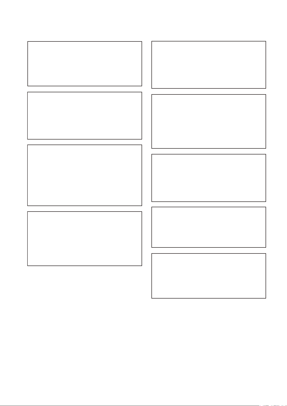
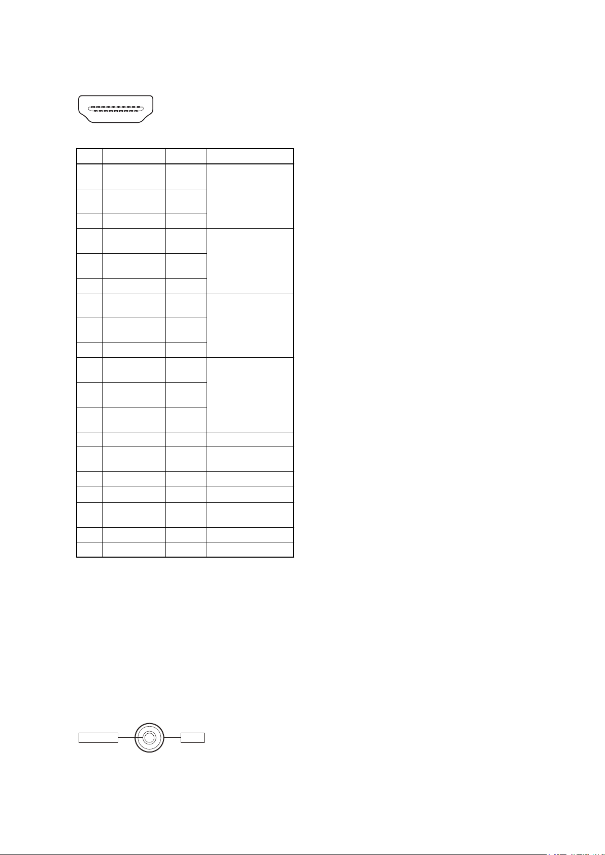
1-1. Signal Inputs and Outputs.....................................................................................................1-1
1-2. Applicable Connectors and Cables............................................................................................1-3
1-3. Location of Main Parts........................................................................................................1-4
1-4. Functions of Onboard Switches and LED Indicators......................................................................... 1-5
1-4-1. Functions of Onboard Switches........................................................................................ 1-5
1-4-2. Description of Onboard LED Indicators................................................................................1-7
1-5. Circuit Protection Parts...................................................................................................... 1-10
1-5-1. Replacing Fuse........................................................................................................ 1-10
1-5-2. Circuit Protection Element............................................................................................1-10
1-6. Fixtures.......................................................................................................................1-11
1-7. Actions to Be Taken in Replacing Parts..................................................................................... 1-12
1-7-1. After Replacement of EEPROM......................................................................................1-12
1-7-2. In Replacing the HPR-56 Board...................................................................................... 1-12
1-7-3. After Replacement of Lithium Battery for Backup................................................................... 1-12
1-7-4. SSD Module (mSATA Assembly).....................................................................................1-12
1-8. Software Update............................................................................................................. 1-17
1-9. Solutions for the Unit Which Does Not Startup Normally.................................................................. 1-18
1-9-1. Unit Shows Black Screen and Does Not Startup Normally...........................................................1-18
1-9-2. Unit Restarts Repeatedly..............................................................................................1-18
1-10. Recovery Method............................................................................................................ 1-20
1-10-1. Procedure..............................................................................................................1-20
1-11. Circuit Description...........................................................................................................1-24
1-11-1. COMe Module........................................................................................................ 1-24
1-11-2. HPR-56 Board.........................................................................................................1-24
1-11-3. IF-1277 Board.........................................................................................................1-25
1-11-4. DY-27 Board.......................................................................................................... 1-26
1-11-5. KY-740 Board.........................................................................................................1-27
1-12. Flexible Card Wire and Coaxial Cable.......................................................................................1-28
1-12-1. Connecting/Disconnecting Flexible Card Wire.......................................................................1-28
1-12-2. Disconnecting/Connecting Fine-Wire Coaxial Cable.................................................................1-28
1-13. Lead-free Solder............................................................................................................. 1-30
2. Error Messages and Warning Messages
2-1. Message Lists................................................................................................................. 2-1
2-1-1. Error Messages .........................................................................................................2-1
2-1-2. Warning Messages......................................................................................................2-1
PMW-PZ1 1