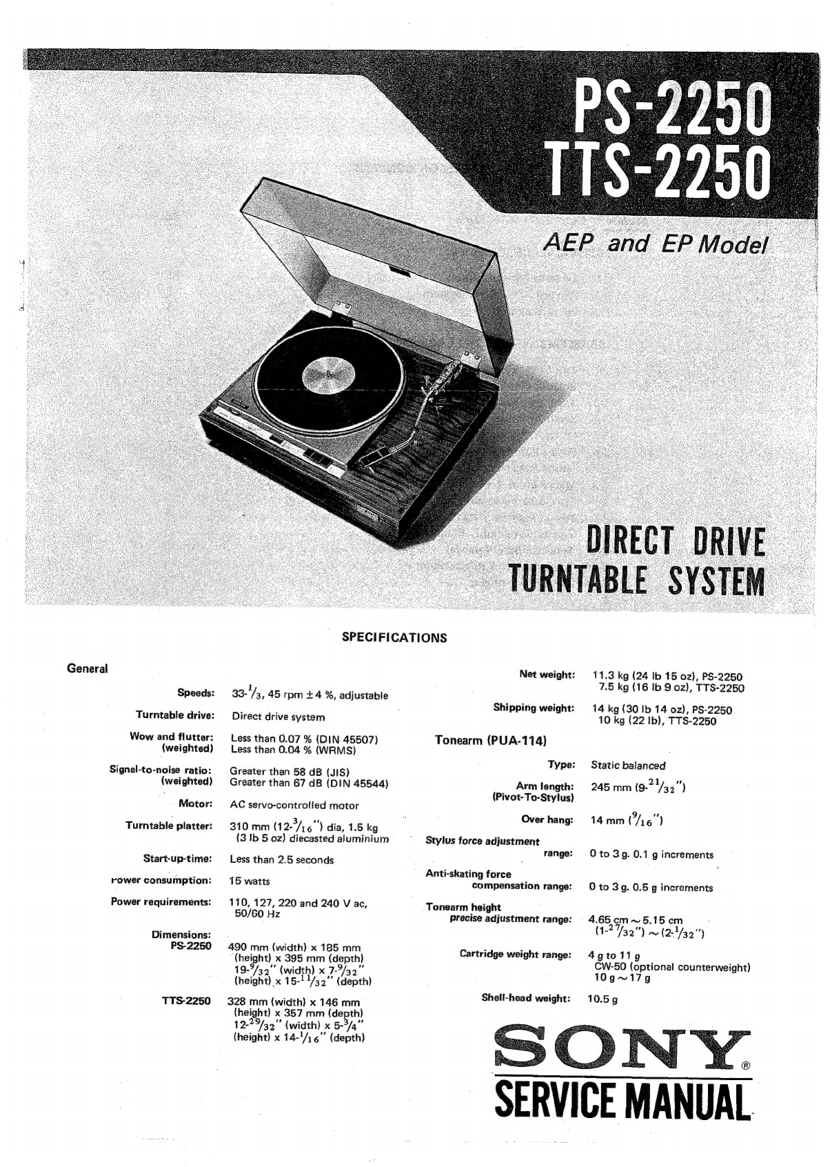
Sony PS-2250 User manual
Other Sony Turntable manuals

Sony
Sony MDX-F5800 User manual

Sony
Sony MDH-10 User manual

Sony
Sony PS-LX55C User manual

Sony
Sony PS-X6 Setup guide

Sony
Sony PS-LX350H User manual

Sony
Sony LocationFree LFA-PC2 User manual

Sony
Sony AIVA AZ-BS1 User manual

Sony
Sony HP-210 User manual

Sony
Sony PS-FL7II - Stereo Turntable User manual

Sony
Sony PMW-PZ1 User manual

Sony
Sony PS-LX56 User manual

Sony
Sony Walkman WM-EX600 User manual

Sony
Sony PS-LX120D User manual

Sony
Sony NW-A45 User manual

Sony
Sony PS-LX310BT User manual

Sony
Sony MDX-C6500RX Product guide

Sony
Sony PS-LX310BT User manual

Sony
Sony PS-X75 User manual

Sony
Sony PS-FL7II - Stereo Turntable Parts list manual

Sony
Sony PS-X60 User manual