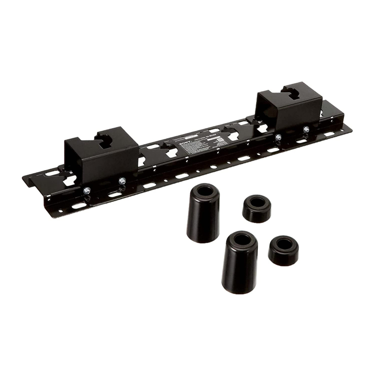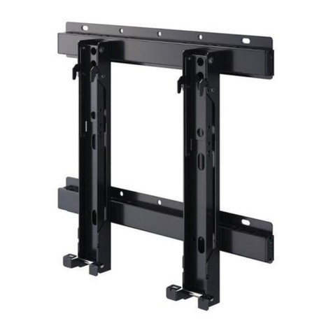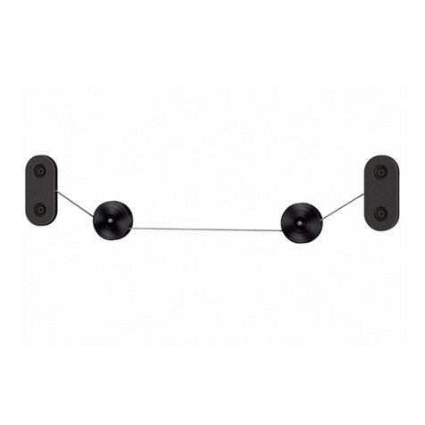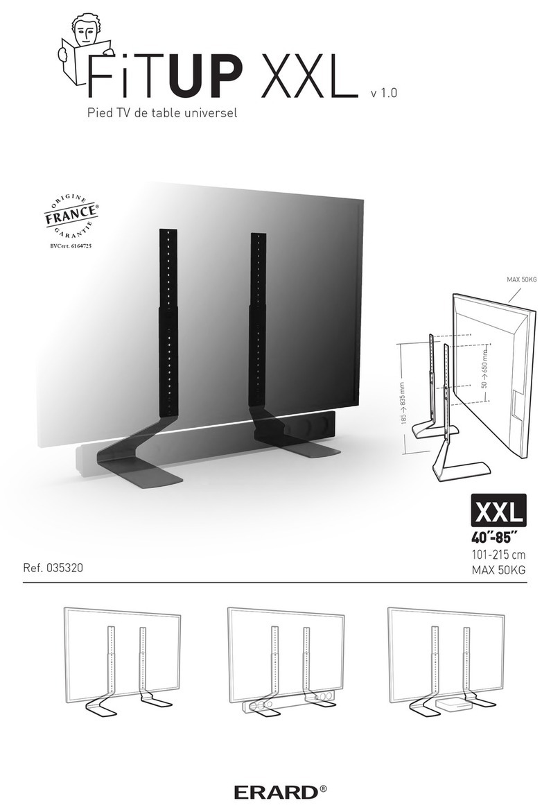
CH-SSTLU Installation Instructions
2
DISCLAIMER
Sony Electronics, Inc., and its affiliated corporations and
subsidiaries (collectively, "Sony"), intend to make this manual
accurate and complete. However, Sony makes no claim that the
information contained herein covers all details, conditions or
variations, nor does it provide for every possible contingency in
connection with the installation or use of this product. The
information contained in this document is subject to change
without notice or obligation of any kind. Sony makes no
representation of warranty, expressed or implied, regarding the
information contained herein. Sony assumes no responsibility
for accuracy, completeness or sufficiency of the information
contained in this document.
IMPORTANT WARNINGS AND
CAUTIONS!
WARNING: A WARNING alerts you to the possibility of
serious injury or death if you do not follow the instructions.
CAUTION: A CAUTION alerts you to the possibility of
damage or destruction of equipment if you do not follow the
corresponding instructions.
WARNING: Failure to read, thoroughly understand, and
follow all instructions can result in serious personal injury,
damage to equipment, or voiding of factory warranty! It is the
installer’s responsibility to make sure all components are
properly assembled and installed using the instructions
provided.
WARNING: Failure to provide adequate structural strength
for this component can result in serious personal injury or
damage to equipment! It is the installer’s responsibility to
make sure the structure to which this component is attached
can support five times the combined weight of all equipment.
Reinforce the structure as required before installing the
component.
WARNING: Exceeding the weight capacity can result in
serious personal injury or damage to equipment! It is the
installer’s responsibility to make sure the combined weight of
all components located between the CH-SSTLU up to (and
including) the display does not exceed 125 lbs (56.7 kg).Use
with products heavier than the maximum weight indicated
may result in collapse of the mount and its accessories
causing possible injury.
DIMENSIONS
15.75in
MAX HEIGHT
400mm
23.62in
MAX WIDTH
600mm
8mm
15.61in
397mm
ROLL ADJUST
.50 [13mm]
HOLES
140mm
4.47in
113mm
STOPS AT 15 , 30 , 45
90
ADJUSTABLE ROTATION
DIMENSIONS: [MILLIMETERS]
INCHES

