SORIN GROUP S5 System Operating instructions
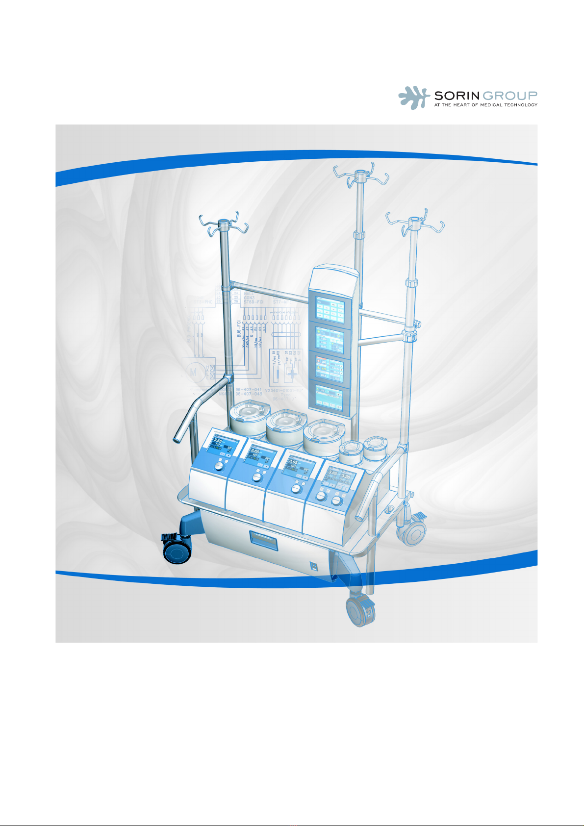
S5 System
Service Instructions

SM-5811-0000.01 ENG
S5 System • Service Instructions
Copyright © 2005 - 2008
SORIN GROUP DEUTSCHLAND GMBH
Lindberghstrasse 25
D-80939 München, Germany
Telephone:+49 - (0)89 - 32301-0
Telefax: +49 - (0)89 - 32301-777
All rights reserved, especially the right to reproduction and distribution as well as translation. No part of
this document may be reproduced – by photocopy, microfilm or any other process – nor may any part of
it be stored, edited, duplicated or distributed by electronic means without the written permission of
SORIN GROUP DEUTSCHLAND GMBH.
Service Instructions
Version 04/2008 - SM-5811-0000.01 ENG

S5 System • Table of Contents
SM-5811-0000.01 ENG 1
Table of Contents
1Introduction
1.1 About the Service Instructions . . . . . . . . . . . . . . . . . . . . . . . . . . . . . . . . . . . . . . . . . . . . . . . . . . . . . 1.1
1.1.1 Symbols used in these Service Instructions . . . . . . . . . . . . . . . . . . . . . . . . . . . . . . . . . . . . . . 1.1
1.1.2 Chapters in these Service Instructions . . . . . . . . . . . . . . . . . . . . . . . . . . . . . . . . . . . . . . . . . . 1.2
1.2 Terminology and abbreviations . . . . . . . . . . . . . . . . . . . . . . . . . . . . . . . . . . . . . . . . . . . . . . . . . . . . . 1.3
2Safety
2.1 Approvals . . . . . . . . . . . . . . . . . . . . . . . . . . . . . . . . . . . . . . . . . . . . . . . . . . . . . . . . . . . . . . . . . . . . . . 2.1
2.2 Regulations and Safety Instructions . . . . . . . . . . . . . . . . . . . . . . . . . . . . . . . . . . . . . . . . . . . . . . . . . 2.1
2.2.1 Use in Accordance with Regulations . . . . . . . . . . . . . . . . . . . . . . . . . . . . . . . . . . . . . . . . . . . . 2.1
2.2.2 General Instructions. . . . . . . . . . . . . . . . . . . . . . . . . . . . . . . . . . . . . . . . . . . . . . . . . . . . . . . . . 2.2
2.2.3 Safety instructions during use. . . . . . . . . . . . . . . . . . . . . . . . . . . . . . . . . . . . . . . . . . . . . . . . . 2.3
2.2.4 Operational Safety . . . . . . . . . . . . . . . . . . . . . . . . . . . . . . . . . . . . . . . . . . . . . . . . . . . . . . . . . . 2.4
2.2.5 Electrical Safety . . . . . . . . . . . . . . . . . . . . . . . . . . . . . . . . . . . . . . . . . . . . . . . . . . . . . . . . . . . . 2.4
2.2.6 Safety Instructions for Routine Maintenance . . . . . . . . . . . . . . . . . . . . . . . . . . . . . . . . . . . . . 2.5
2.2.7 Safety instructions for service technicians . . . . . . . . . . . . . . . . . . . . . . . . . . . . . . . . . . . . . . . 2.5
2.3 Safety feature on the S5 System . . . . . . . . . . . . . . . . . . . . . . . . . . . . . . . . . . . . . . . . . . . . . . . . . . . . 2.5
3 System description
3.1 General description . . . . . . . . . . . . . . . . . . . . . . . . . . . . . . . . . . . . . . . . . . . . . . . . . . . . . . . . . . . . . . 3.1
3.2 Layout of the S5 System . . . . . . . . . . . . . . . . . . . . . . . . . . . . . . . . . . . . . . . . . . . . . . . . . . . . . . . . . . . 3.1
3.2.1 Total overview . . . . . . . . . . . . . . . . . . . . . . . . . . . . . . . . . . . . . . . . . . . . . . . . . . . . . . . . . . . . . . 3.2
3.2.2 Overview of mast pump systems (optional) . . . . . . . . . . . . . . . . . . . . . . . . . . . . . . . . . . . . . . 3.6
3.2.3 Overview of S5 System Panel. . . . . . . . . . . . . . . . . . . . . . . . . . . . . . . . . . . . . . . . . . . . . . . . . . 3.8
System panel (standard) . . . . . . . . . . . . . . . . . . . . . . . . . . . . . . . . . . . . . . . . . . . . . . . . . . . . . 3.8
System panel (optional) . . . . . . . . . . . . . . . . . . . . . . . . . . . . . . . . . . . . . . . . . . . . . . . . . . . . . . 3.9
3.2.4 Overview of the electronic / and power pack . . . . . . . . . . . . . . . . . . . . . . . . . . . . . . . . . . . . . 3.10
3.2.5 Overview of pumps and pump control panels . . . . . . . . . . . . . . . . . . . . . . . . . . . . . . . . . . . . 3.12
S5 roller pump 150 and S5 double roller pump 85 . . . . . . . . . . . . . . . . . . . . . . . . . . . . . . . . . 3.12
S5 mast roller pumps . . . . . . . . . . . . . . . . . . . . . . . . . . . . . . . . . . . . . . . . . . . . . . . . . . . . . . . . 3.14

S5 System • Table of Contents
2SM-5811-0000.01 ENG
3.3 Service-relevant assemblies . . . . . . . . . . . . . . . . . . . . . . . . . . . . . . . . . . . . . . . . . . . . . . . . . . . . . . . . 3.16
3.3.1 Assembly overview – E/P pack. . . . . . . . . . . . . . . . . . . . . . . . . . . . . . . . . . . . . . . . . . . . . . . . . 3.18
Overview of E/P pack. . . . . . . . . . . . . . . . . . . . . . . . . . . . . . . . . . . . . . . . . . . . . . . . . . . . . . . . . 3.18
Overview – Switching power supply . . . . . . . . . . . . . . . . . . . . . . . . . . . . . . . . . . . . . . . . . . . . 3.21
3.3.2 Assembly overview – S5 RP 150 . . . . . . . . . . . . . . . . . . . . . . . . . . . . . . . . . . . . . . . . . . . . . . . . 3.22
3.3.3 Assembly overview – DRP 85 . . . . . . . . . . . . . . . . . . . . . . . . . . . . . . . . . . . . . . . . . . . . . . . . . . 3.24
3.3.4 Assembly overview – System panel . . . . . . . . . . . . . . . . . . . . . . . . . . . . . . . . . . . . . . . . . . . . . 3.26
System panel (4 pos.) . . . . . . . . . . . . . . . . . . . . . . . . . . . . . . . . . . . . . . . . . . . . . . . . . . . . . . . . 3.26
System panel (3 pos. and 6 pos.) . . . . . . . . . . . . . . . . . . . . . . . . . . . . . . . . . . . . . . . . . . . . . . . 3.27
3.3.5 Assembly overview – Sensor modules. . . . . . . . . . . . . . . . . . . . . . . . . . . . . . . . . . . . . . . . . . . 3.29
3.3.6 Assembly overview – S5 MRP 150 . . . . . . . . . . . . . . . . . . . . . . . . . . . . . . . . . . . . . . . . . . . . . . 3.31
3.3.7 Assembly overview – S5 MRP 85/1 and S5 MRP 85/2. . . . . . . . . . . . . . . . . . . . . . . . . . . . . . . 3.32
3.3.8 Assembly overview – Control panels for mast roller pumps . . . . . . . . . . . . . . . . . . . . . . . . . 3.33
3.3.9 Assembly overview SCP System for S5 . . . . . . . . . . . . . . . . . . . . . . . . . . . . . . . . . . . . . . . . . . 3.35
3.3.10 Overview – Circuit boards. . . . . . . . . . . . . . . . . . . . . . . . . . . . . . . . . . . . . . . . . . . . . . . . . . . . . 3.36
Overview Backplane E/N-Block . . . . . . . . . . . . . . . . . . . . . . . . . . . . . . . . . . . . . . . . . . . . . . . . 3.36
Circuit board motor controller . . . . . . . . . . . . . . . . . . . . . . . . . . . . . . . . . . . . . . . . . . . . . . . . . 3.40
Circuit board motor power amplifier . . . . . . . . . . . . . . . . . . . . . . . . . . . . . . . . . . . . . . . . . . . . 3.41
Circuit board computer board. . . . . . . . . . . . . . . . . . . . . . . . . . . . . . . . . . . . . . . . . . . . . . . . . . 3.42
Circuit board inverter (pumps) . . . . . . . . . . . . . . . . . . . . . . . . . . . . . . . . . . . . . . . . . . . . . . . . . 3.43
Circuit board keys and LEDs . . . . . . . . . . . . . . . . . . . . . . . . . . . . . . . . . . . . . . . . . . . . . . . . . . . 3.44
Overview backplane system panel (4 pos. and 5 pos.) . . . . . . . . . . . . . . . . . . . . . . . . . . . . . . 3.45
Overview backplane system panel (3 pos. and 6 pos.). . . . . . . . . . . . . . . . . . . . . . . . . . . . . . 3.47
Overview circuit board display and control module . . . . . . . . . . . . . . . . . . . . . . . . . . . . . . . . 3.48
Circuit board inverter (system-panel and control panel) . . . . . . . . . . . . . . . . . . . . . . . . . . . . 3.49
Circuit board fan control (control panel mast roller pumps). . . . . . . . . . . . . . . . . . . . . . . . . . 3.50
Circuit board mast roller pumps 85 (motor controller and motor power amplifier) . . . . . . . 3.51
4 Brief overview system panel
4.1 Key icons and display (brief overview) . . . . . . . . . . . . . . . . . . . . . . . . . . . . . . . . . . . . . . . . . . . . . . . 4.1
General key icons and displays . . . . . . . . . . . . . . . . . . . . . . . . . . . . . . . . . . . . . . . . . . . . . . . .4.1
Key icons and displays of the system menu . . . . . . . . . . . . . . . . . . . . . . . . . . . . . . . . . . . . . .4.3
5 Fault messages and troubleshooting
5.1 Fault messages . . . . . . . . . . . . . . . . . . . . . . . . . . . . . . . . . . . . . . . . . . . . . . . . . . . . . . . . . . . . . . . . . . 5.1
5.1.1 Unspecified faults . . . . . . . . . . . . . . . . . . . . . . . . . . . . . . . . . . . . . . . . . . . . . . . . . . . . . . . . . . . 5.1
5.1.2 Fault messages . . . . . . . . . . . . . . . . . . . . . . . . . . . . . . . . . . . . . . . . . . . . . . . . . . . . . . . . . . . . . 5.2
Fault on pump . . . . . . . . . . . . . . . . . . . . . . . . . . . . . . . . . . . . . . . . . . . . . . . . . . . . . . . . . . . . . . 5.2
Battery fault . . . . . . . . . . . . . . . . . . . . . . . . . . . . . . . . . . . . . . . . . . . . . . . . . . . . . . . . . . . . . . . . 5.5
Faults in the sensor modules or sensors . . . . . . . . . . . . . . . . . . . . . . . . . . . . . . . . . . . . . . . . . 5.7
5.2 Operating the additional devices for the S5 System . . . . . . . . . . . . . . . . . . . . . . . . . . . . . . . . . . . . 5.8
Other displays . . . . . . . . . . . . . . . . . . . . . . . . . . . . . . . . . . . . . . . . . . . . . . . . . . . . . . . . . . . . . . 5.8

S5 System • Table of Contents
SM-5811-0000.01 ENG 3
6 Replacing components
6.1 E/P pack . . . . . . . . . . . . . . . . . . . . . . . . . . . . . . . . . . . . . . . . . . . . . . . . . . . . . . . . . . . . . . . . . . . . . . . 6.1
Removing the E/P pack . . . . . . . . . . . . . . . . . . . . . . . . . . . . . . . . . . . . . . . . . . . . . . . . . . . . . . 6.1
Opening the E/P pack. . . . . . . . . . . . . . . . . . . . . . . . . . . . . . . . . . . . . . . . . . . . . . . . . . . . . . . . 6.3
Removing the system boards. . . . . . . . . . . . . . . . . . . . . . . . . . . . . . . . . . . . . . . . . . . . . . . . . . 6.5
Removing the switching power supply . . . . . . . . . . . . . . . . . . . . . . . . . . . . . . . . . . . . . . . . . . 6.6
Replacing the batteries . . . . . . . . . . . . . . . . . . . . . . . . . . . . . . . . . . . . . . . . . . . . . . . . . . . . . . 6.8
Replacing the battery switch circuit board . . . . . . . . . . . . . . . . . . . . . . . . . . . . . . . . . . . . . . . 6.9
Replacing fuses (Circuit board battery switch) . . . . . . . . . . . . . . . . . . . . . . . . . . . . . . . . . . . . 6.10
6.2 Pumps . . . . . . . . . . . . . . . . . . . . . . . . . . . . . . . . . . . . . . . . . . . . . . . . . . . . . . . . . . . . . . . . . . . . . . . . . 6.11
6.2.1 Opening the pump housing and removing the pump head . . . . . . . . . . . . . . . . . . . . . . . . . . 6.11
Removal of roller pump 150 . . . . . . . . . . . . . . . . . . . . . . . . . . . . . . . . . . . . . . . . . . . . . . . . . . . 6.18
6.2.2 Removal of the pump control panel and touch screen. . . . . . . . . . . . . . . . . . . . . . . . . . . . . . 6.20
Removing the shaft encoder . . . . . . . . . . . . . . . . . . . . . . . . . . . . . . . . . . . . . . . . . . . . . . . . . . 6.26
6.2.3 Replacing the line filter on the pumps . . . . . . . . . . . . . . . . . . . . . . . . . . . . . . . . . . . . . . . . . . 6.28
6.3 Mast roller pump MRP150 . . . . . . . . . . . . . . . . . . . . . . . . . . . . . . . . . . . . . . . . . . . . . . . . . . . . . . . . . 6.29
6.3.1 Opening the pump housing . . . . . . . . . . . . . . . . . . . . . . . . . . . . . . . . . . . . . . . . . . . . . . . . . . . 6.29
6.3.2 Removing the mast roller pump MRP 150 . . . . . . . . . . . . . . . . . . . . . . . . . . . . . . . . . . . . . . . . 6.32
6.4 Mast roller pump MRP85/x . . . . . . . . . . . . . . . . . . . . . . . . . . . . . . . . . . . . . . . . . . . . . . . . . . . . . . . . 6.33
6.4.1 Removing the double holder . . . . . . . . . . . . . . . . . . . . . . . . . . . . . . . . . . . . . . . . . . . . . . . . . . 6.33
6.4.2 Opening the pump housing . . . . . . . . . . . . . . . . . . . . . . . . . . . . . . . . . . . . . . . . . . . . . . . . . . . 6.34
6.4.3 Replacing circuit boards. . . . . . . . . . . . . . . . . . . . . . . . . . . . . . . . . . . . . . . . . . . . . . . . . . . . . . 6.35
6.4.4 Removing the pump head . . . . . . . . . . . . . . . . . . . . . . . . . . . . . . . . . . . . . . . . . . . . . . . . . . . . 6.40
6.5 System Panel . . . . . . . . . . . . . . . . . . . . . . . . . . . . . . . . . . . . . . . . . . . . . . . . . . . . . . . . . . . . . . . . . . . 6.42
6.5.1 Opening the system panel . . . . . . . . . . . . . . . . . . . . . . . . . . . . . . . . . . . . . . . . . . . . . . . . . . . . 6.42
6.5.2 Replacing the circuit board backplane . . . . . . . . . . . . . . . . . . . . . . . . . . . . . . . . . . . . . . . . . . 6.46
6.5.3 Replacing components of the display and control module . . . . . . . . . . . . . . . . . . . . . . . . . . 6.47
Replacing the display and control module . . . . . . . . . . . . . . . . . . . . . . . . . . . . . . . . . . . . . . . 6.48
Replacing the circuit board Inverter . . . . . . . . . . . . . . . . . . . . . . . . . . . . . . . . . . . . . . . . . . . . 6.49
Replacing the touch screen . . . . . . . . . . . . . . . . . . . . . . . . . . . . . . . . . . . . . . . . . . . . . . . . . . . 6.50
6.6 Control panels for mast roller pumps . . . . . . . . . . . . . . . . . . . . . . . . . . . . . . . . . . . . . . . . . . . . . . . . 6.51
6.6.1 Opening the control panel . . . . . . . . . . . . . . . . . . . . . . . . . . . . . . . . . . . . . . . . . . . . . . . . . . . . 6.51
6.6.2 Replacing control panel components . . . . . . . . . . . . . . . . . . . . . . . . . . . . . . . . . . . . . . . . . . . 6.53
Replacing the circuit board fan control . . . . . . . . . . . . . . . . . . . . . . . . . . . . . . . . . . . . . . . . . . 6.53
Replacing circuit boards. . . . . . . . . . . . . . . . . . . . . . . . . . . . . . . . . . . . . . . . . . . . . . . . . . . . . . 6.54
Replacing the touch screen . . . . . . . . . . . . . . . . . . . . . . . . . . . . . . . . . . . . . . . . . . . . . . . . . . . 6.57
Removing the shaft encoder . . . . . . . . . . . . . . . . . . . . . . . . . . . . . . . . . . . . . . . . . . . . . . . . . . 6.58
6.7 Replacing circuit boards/sensor modules . . . . . . . . . . . . . . . . . . . . . . . . . . . . . . . . . . . . . . . . . . . . 6.60
6.8 Connectors . . . . . . . . . . . . . . . . . . . . . . . . . . . . . . . . . . . . . . . . . . . . . . . . . . . . . . . . . . . . . . . . . . . . . 6.62
6.8.1 E/P pack connectors. . . . . . . . . . . . . . . . . . . . . . . . . . . . . . . . . . . . . . . . . . . . . . . . . . . . . . . . . 6.62
ODU plug . . . . . . . . . . . . . . . . . . . . . . . . . . . . . . . . . . . . . . . . . . . . . . . . . . . . . . . . . . . . . . . . . . 6.62
Amphenol plug . . . . . . . . . . . . . . . . . . . . . . . . . . . . . . . . . . . . . . . . . . . . . . . . . . . . . . . . . . . . . 6.62
6.8.2 Circuit boards connectors . . . . . . . . . . . . . . . . . . . . . . . . . . . . . . . . . . . . . . . . . . . . . . . . . . . . 6.63
Phoenix plug and socket . . . . . . . . . . . . . . . . . . . . . . . . . . . . . . . . . . . . . . . . . . . . . . . . . . . . . 6.63
FCI plug and socket . . . . . . . . . . . . . . . . . . . . . . . . . . . . . . . . . . . . . . . . . . . . . . . . . . . . . . . . . 6.63
Molex plug and socket . . . . . . . . . . . . . . . . . . . . . . . . . . . . . . . . . . . . . . . . . . . . . . . . . . . . . . . 6.64
AMP plug and socket . . . . . . . . . . . . . . . . . . . . . . . . . . . . . . . . . . . . . . . . . . . . . . . . . . . . . . . . 6.64

S5 System • Table of Contents
4SM-5811-0000.01 ENG
7Appendix
7.1 S5 system specifications . . . . . . . . . . . . . . . . . . . . . . . . . . . . . . . . . . . . . . . . . . . . . . . . . . . . . . . . . . 7.1
7.1.1 Dimensions, weights, operating conditions . . . . . . . . . . . . . . . . . . . . . . . . . . . . . . . . . . . . . . 7.1
Console . . . . . . . . . . . . . . . . . . . . . . . . . . . . . . . . . . . . . . . . . . . . . . . . . . . . . . . . . . . . . . . . . . . 7.1
Masts . . . . . . . . . . . . . . . . . . . . . . . . . . . . . . . . . . . . . . . . . . . . . . . . . . . . . . . . . . . . . . . . . . . . . 7.2
Pumps . . . . . . . . . . . . . . . . . . . . . . . . . . . . . . . . . . . . . . . . . . . . . . . . . . . . . . . . . . . . . . . . . . . . 7.3
System panel . . . . . . . . . . . . . . . . . . . . . . . . . . . . . . . . . . . . . . . . . . . . . . . . . . . . . . . . . . . . . . . 7.4
7.1.2 Electrical Specifications . . . . . . . . . . . . . . . . . . . . . . . . . . . . . . . . . . . . . . . . . . . . . . . . . . . . . . 7.5
Electronics and power pack . . . . . . . . . . . . . . . . . . . . . . . . . . . . . . . . . . . . . . . . . . . . . . . . . . .7.5
UPS and batteries . . . . . . . . . . . . . . . . . . . . . . . . . . . . . . . . . . . . . . . . . . . . . . . . . . . . . . . . . . . 7.5
Shelf with AC outlet. . . . . . . . . . . . . . . . . . . . . . . . . . . . . . . . . . . . . . . . . . . . . . . . . . . . . . . . . . 7.6
System panel . . . . . . . . . . . . . . . . . . . . . . . . . . . . . . . . . . . . . . . . . . . . . . . . . . . . . . . . . . . . . . . 7.6
Modules and sensors . . . . . . . . . . . . . . . . . . . . . . . . . . . . . . . . . . . . . . . . . . . . . . . . . . . . . . . . 7.7
7.1.3 Pumps . . . . . . . . . . . . . . . . . . . . . . . . . . . . . . . . . . . . . . . . . . . . . . . . . . . . . . . . . . . . . . . . . . . . 7.9
7.2 Labelling . . . . . . . . . . . . . . . . . . . . . . . . . . . . . . . . . . . . . . . . . . . . . . . . . . . . . . . . . . . . . . . . . . . . . . . 7.11
7.3 Partnumbers, standard components and accessories . . . . . . . . . . . . . . . . . . . . . . . . . . . . . . . . . . . 7.13
7.3.1 S5 System . . . . . . . . . . . . . . . . . . . . . . . . . . . . . . . . . . . . . . . . . . . . . . . . . . . . . . . . . . . . . . . . . 7.13
7.3.2 System accessories. . . . . . . . . . . . . . . . . . . . . . . . . . . . . . . . . . . . . . . . . . . . . . . . . . . . . . . . . . 7.17
7.3.3 Additional devices and accessories. . . . . . . . . . . . . . . . . . . . . . . . . . . . . . . . . . . . . . . . . . . . .7.20
7.4 Disposables and accessories . . . . . . . . . . . . . . . . . . . . . . . . . . . . . . . . . . . . . . . . . . . . . . . . . . . . . . . 7.22
7.5 Service component part numbers . . . . . . . . . . . . . . . . . . . . . . . . . . . . . . . . . . . . . . . . . . . . . . . . . . . 7.23
7.5.1 S5 System separate components. . . . . . . . . . . . . . . . . . . . . . . . . . . . . . . . . . . . . . . . . . . . . . . 7.23
Accessories for E/P pack. . . . . . . . . . . . . . . . . . . . . . . . . . . . . . . . . . . . . . . . . . . . . . . . . . . . . . 7.23
Assembly RP 150 . . . . . . . . . . . . . . . . . . . . . . . . . . . . . . . . . . . . . . . . . . . . . . . . . . . . . . . . . . . . 7.24
Assembly System panel . . . . . . . . . . . . . . . . . . . . . . . . . . . . . . . . . . . . . . . . . . . . . . . . . . . . . .7.27
Assembly Sensor modules . . . . . . . . . . . . . . . . . . . . . . . . . . . . . . . . . . . . . . . . . . . . . . . . . . . . 7.29
7.5.2 Additional assemblies and components . . . . . . . . . . . . . . . . . . . . . . . . . . . . . . . . . . . . . . . . . 7.32
Console accessories . . . . . . . . . . . . . . . . . . . . . . . . . . . . . . . . . . . . . . . . . . . . . . . . . . . . . . . . . 7.32
Pump spacer accessories . . . . . . . . . . . . . . . . . . . . . . . . . . . . . . . . . . . . . . . . . . . . . . . . . . . . . 7.32
Mast roller pumps and control panels accessories. . . . . . . . . . . . . . . . . . . . . . . . . . . . . . . . . 7.32
Cables and/or wiring sets. . . . . . . . . . . . . . . . . . . . . . . . . . . . . . . . . . . . . . . . . . . . . . . . . . . . . 7.35
Mast accessories . . . . . . . . . . . . . . . . . . . . . . . . . . . . . . . . . . . . . . . . . . . . . . . . . . . . . . . . . . . 7.36

S5 System • Introduction
SM-5811-0000.01 ENG 1.1
1 Introduction
1.1 About the Service Instructions
These Service Instructions (along with the training given by SORIN GROUP DEUTSCHLAND GMBH) provide
basic information on the maintenance and repair of your S5 System. This manual has been designed
solely for use by suitably qualified service technicians. In the interest of the safety of patients and all
users:
!
Only service technicians who have been trained and duly authorised by
SORIN GROUP DEUTSCHLAND GMBH may perform service on the S5 System.
All information on the operation of the S5 System can be found in the Operating Instructions. These
Service Instructions will refer to the appropriate chapter of the Operating Instructions as required.
1.1.1 Symbols used in these Service Instructions
The symbols are intended to help the user find particular text passages. The meaning of the symbols is
as follows:
!Danger! Failure to pay attention may put the health and safety of the patient
and/or the operator at risk.
!Warning! Failure to pay attention may cause damage to the machine or other
equipment.
✓A check list for a quick and safe follow-up on whether operational steps have
been carried out completely.
◗Primary list (main groups)
➜Secondary list (subgroups)

S5 System • Introduction
1.2 SM-5811-0000.01 ENG
1.1.2 Chapters in these Service Instructions
In chapter... you will find the following information:
1 Introduction – Symbols in the Service Instructions
– Overview on chapters (this table)
– Terminology and abbreviations
2 Safety – Important safety instructions for the operation of the S5
System
– Safety instructions for service technicians
3 System description – Brief description of all service-relevant components
4 Brief overview system panel – Brief overview of all key icons and displays
5 Fault messages and troubleshooting – List of all fault messages and fault isolation tips
6 Replacing components – Information and instructions on the removal and
installation of components
7 Appendix – Technical data and components
– Part numbers / spare parts

S5 System • Introduction
SM-5811-0000.01 ENG 1.3
1.2 Terminology and abbreviations
◗S5 System Stöckert S5 System, modular heart-lung-machine
◗S5 console 4 position
(abbreviation: console)
Contains the electronic / power supply pack with the fans
and accumulators for the emergency power supply
4 console casters with 4 parking brakes
◗S5 console plate 4 position
(abbreviation: console plate)
Located on the console:
– Supports 4 pump housings or units
– With mast retaining flanges (for supporting the push
bars and telescope masts)
– With push bars (left and right)
– With crossbar on the back for the movable mast
◗S5 electronics and power pack
(abbreviation: E/P pack)
The electronics / and power pack is located inside the
console. The E/P pack comprises the power-supply
components (including the emergency power supply), the
system connection panel and the necessary sensor
modules.
S5 power supply module
S5 UPS module
S5 DC/DC module
S5 battery discharger
◗S5 sensor module The sensor module measures all the recorded values (such
as the temperature from a temperature sensor). The values
are shown on the corresponding displet (e.g. Temperature
1) via the CAN bus.
◗S5 mast retaining flange, left
◗S5 mast retaining flange, right
Side components for supporting the sliding T-bar handles
and telescopic masts
◗S5 mast system (complete) Comprises:
– Two vertical telescope masts
– One movable telescope mast
– Push bars (left and right)
– Horizontal mast
– Crossbar for movable mast
◗S5 telescope mast with infusion rack
(abbreviation: telescope mast)
Fixed telescope mast
with 4-arm bottle holder
◗S5 telescope mast, movable with
infusion rack
(abbreviation: movable mast)
Movable telescope mast with 4-arm bottle holder
◗S5 crossbar for movable mast 4 position
(abbreviation: crossbar for movable
mast)
Permanently mounted on the back of the console for
supporting the movable telescope mast
◗S5 horizontal mast 4 position
(abbreviation: horizontal mast)
With 2 mast retainers (left and right) for attachment to the
vertical masts

S5 System • Introduction
1.4 SM-5811-0000.01 ENG
◗S5 system panel 4 position
(abbreviation: system panel)
The modular control unit mounted on the mast comprises
4 module slots to take a maximum of 4 display and control
modules with touch screens.
Blank modules are plugged into slots which are not being
used.
◗S5 display and control module Central interface between the user and the S5 System
comprising:
– Touch screen
–Housing
◗Touch screen
(pressure-sensitive display)
This is where
– All the values recorded by the sensors, the states and
the parameters defined by the user (such as limits) are
displayed
– The control functions are assigned to the
corresponding pumps
– The entire system is configured
The surface of the touch screen is divided up into several
displets (according to menu and display).
◗Display applet
(abbreviation: displet)
A display applet is the display of an application. This
application may concern displets for displaying the current
values (such as the measured pressure) or so-called entry
displets where parameters or limits can be entered.
The number of displets shown depends on the
configuration of the entire system, the menus which have
been selected and the current status of the heart-lung-
machine.
◗Start page After switching on, if the self-test has run without any
faults (the S5 System and the system panel), the start page
will appear on the system panel.
The Start page is dependent on the total configuration of
the system and the parameters last saved in the
–Systemmenu
–UPSmenu
– Menus for the control and monitoring functions
– Menus for the monitoring functions
– Display menu
– Equipment menu (optional)
◗Main menu (Main page) Overall display of all menus during operation on the
system panel.
◗System menu This is where the:
– Displays date and time
– Displays alarm, warning and error messages
– Deletes, clears and silences pending alarms
◗UPS menu This is where the:
– Monitor and control of UPS functions
– Shows the current operating state of the UPS

S5 System • Introduction
SM-5811-0000.01 ENG 1.5
◗Monitoring function The term “monitoring function” may also include a control
associated with it. A control in this instance can be the
result of a monitored process. In order to avoid the use of
different terms, therefore, the term “monitoring function”
will be used consistently throughout.
◗Menus for the control and monitoring
functions
The following menus (and corresponding sensor modules
and sensors) are used to control operation and intervene in
the pump control system when there is an alarm:
– Pressure menu
– Level menu
–Bubblemenu
– Cardioplegia menu
◗Menus for the monitoring function The following menus (and corresponding sensor modules
and sensors) can be used to trigger an alarm which,
however, does not intervene in the pump control system:
– Temperature menu
◗Display menu These menus only have a display function:
–Timer
◗Pump menu This is where the:
– Pump parameters are entered
– The blood/cardioplegia and stop link pumps are
assigned
◗Equipment menu (optional) The control panel for external units appears on the
displets.
Parameters can be entered or assigned.
e.g. gas blender (optional)
◗Functional group The displet on the display and control module on the
system panel, the sensor module in the E/P pack and the
corresponding sensor (or sensors) represent a “functional
group” (e.g. “Temperature monitor” displet and sensor
module and the temperature probes).
Although all entry and display displets are combined on
the system panel, each functional group operates
independently.

S5 System • Introduction
1.6 SM-5811-0000.01 ENG
◗S5 Roller pump 150
(abbreviation: S5 RP 150)
Comprises:
– Pump housing
– Pump head with pump track Ø 150 mm
(e.g. for arterial blood flow)
– S5 control panel RP 150
– S5 pump cover RP 150
– S5 tubing clamp block RP 150
– Or S5 tubing clamp Variolock RP 150
– Incl. various Variolock inserts
◗S5 double roller pump 85
(abbreviation: S5 DRP 85)
Comprises:
– Pump housing
– Two independently operating pumps with Ø 85 mm
pump raceways (for low flow rates)
– S5 control panel DRP 85
– S5 pump cover DRP 85
– S5 terminal blocks
DRP 85
◗S5 control panel for RP 150/DRP 85
(abbreviation: control panel)
The control panel is located on the top of the pump housing
and contains the control elements (setting knob and keys)
and the touch screen for the corresponding pump.
◗S5 mast pump system Comprises:
– Corresponding mast-mounted roller pump
e.g. S5 mast roller pump 150 or
1-2 S5 mast roller pump(s) 85
– S5 control panel for MRP 150/MRP 85
or S5 control panel for 2 MPR 85
◗S5 control panel for mast roller pumps
MRP (abbreviation: control panel)
These control panels are integrated into a separate mast-
mounted panel and each comprise a touch screen and the
corresponding control elements.
The control panels operate in exactly the same way as the
control panels for the S5 RP 150 and S5 DRP 85.
The S5 control panel MRP 150/85 differs from the S5
control panel MRP 85 in that the S5 control panel MRP 150/
85 is used to control a mast-roller pump 150 or 85 and the
S5 control panel MRP 85 is used to control two MRP 85s.
◗S5 mast roller pump 150/85
(abbreviation: mast pump)
Mast-mounted roller pumps consist of a pump unit (pump
housing with pump head) and the corresponding control
panels.

S5 System • Introduction
SM-5811-0000.01 ENG 1.7
◗HLM Heart-Lung-Machine
◗EMC ElectroMagnetic Compatibility
◗UPS Uninterruptible Power Supply
◗OT Operating Theatre
◗DMS Data Management System
◗CAN Controller Area Network (CAN bus)
◗BPM (bpm) Pulse frequency per minute (beats per minute)
◗RPM (rpm) Revolutions Per Minute
◗LPM (l/min) Litres Per Minute
◗LCD Liquid Crystal Display
◗PMC (PM) Pulse Mode Control (Pulse Mode)
◗ECG ElectroCardioGram
◗BSA BSA display (Body Surface Area display):
Display for calculating the body surface area
(abbreviation: BSA display)
◗ECC-Timer ECC (Extracorporeal circuit):
Facilitates an independent measuring of time during an
extracorporeal circuit (abbreviation: ECC-Timer).
◗APC Air Purge Control :
An optional S5 System component that facilitates the
controlled removal of bubbles from bubble traps.

S5 System • Introduction
1.8 SM-5811-0000.01 ENG
S5 System • Safety
SM-5811-0000.01 ENG 2.1
2Safety
2.1 Approvals
Like development and manufacturing, service must also be conducted in conformance with the following
standards and statutes:
The S5 System is a medical product, class IIb (MDD 93/42). A Declaration of Conformity has been issued
for the S5 System.
2.2 Regulations and Safety Instructions
2.2.1 Use in Accordance with Regulations
!
◗In accordance with the applicable regulations, the Stöckert S5 System is used to perform, control
and monitor extracorporeal circulation during an operation. Any use outside this specification is not
in accordance with the regulations and SORIN GROUP DEUTSCHLAND GMBH will not assume any
liability for damage in such a case. Use in accordance with regulations also includes compliance with
the operating instructions, as well as repair and maintenance according to the maintenance
instructions.
◗Relevant accident prevention measures according to existing local regulations and employees’
health and safety regulations must be complied with. SORIN GROUP DEUTSCHLAND GMBH will not
accept any liability for damage due to non-compliance with these regulations.
◗SORIN GROUP DEUTSCHLAND GMBH will not assume any liability for injuries and/or damage caused
by failure to observe the safety instructions or operating instructions or by the operator not taking
due care. This also applies if the operator’s duty to take due care has not been specifically expressed
to the user.
IEC 60601-1 – Medical Electrical Equipment: General Requirements
for Safety
IEC 60601-1-2:2001 – EMC (Electromagnetic Compatibility)
VBG – Regulations for Accident Prevention
MDD – Medical Device Directive
(EC Directive 93/42 EEC of 14 June 1993)
DIN EN ISO 13485 – Quality Assurance
–CELabel

S5 System • Safety
2.2 SM-5811-0000.01 ENG
2.2.2 General Instructions
◗The S5 System has been designed according to current state-of-the art technology and accepted
safety standards. However, danger may arise to the patient, the user or other equipment during
operation.
!
◗The S5 System must not be used in the presence of explosive substances.
Use in accordance
with regulations:
See Chapter 2.2.1
on Page 2.1.
◗The S5 System may only be used when the equipment is in perfect technical running order and when
it is used in accordance with the applicable regulations and the operating instructions. Be sure to
take note of cautions and warnings.
◗The operating instructions must be available close to the S5 System at all times. Incomplete or
illegible operating instructions must be replaced immediately.
◗According to the European Directive 93/42 EEC and the national standards based on this directive,
the S5 System must be subjected to a regular maintenance check by an authorised service
technician. The S5 System must be subjected to this maintenance check every 1000 operating hours
or at least every 12 months, whichever comes first.
◗In addition to the operating instructions, the relevant legal, general and binding regulations
concerning the prevention of accidents must be followed.
◗In order to take into account situations which are clinic-specific and outside of normal routines, e. g.
certain working procedures, the operating instructions must be supplemented with relevant
instructions (supervision and registration requirements, etc).
◗Persons operating the S5 System must familiarise themselves thoroughly with the operating
instructions before working on the machine!
Firmware informa-
tion:See Operating
Instructions
◗The firmware installed in the device must correspond to the version numbers listed in the Operating
Instructions.
◗Always switch off the S5 System using the main switch. Otherwise, the batteries may totally
discharge.
◗If modifications affecting safety or performance are noticed when the S5 System is not in use, shut
down the machine immediately and have it checked by an authorised service technician.
◗Do not execute any modifications or extensions to the machine unless they have been tested and
approved by SORIN GROUP DEUTSCHLAND GMBH, otherwise SORIN GROUP DEUTSCHLAND GMBH
cannot assume any liability or responsibility.
Routine Mainte-
nance: See
Operating
Instructions
◗Keep the S5 System clean! This will prevent incorrect contact and faults due to dirt etc.

S5 System • Safety
SM-5811-0000.01 ENG 2.3
2.2.3 Safety instructions during use
◗The S5 System must only be operated and maintained by trained and qualified personnel.
!
◗When in operation, the S5 System must be monitored at all times. Non-compliance with this duty
may result in danger to the patient's health! The safety features of the S5 System (alarm signals etc.)
are intended to assist the user and do not free him from his responsibility to monitor the equipment
continuously and conscientiously.
!
◗A cardiopulmonary bypass requires comprehensive monitoring of both the patient and the perfusion
status. For this reason, all relevant values which are not recorded directly on the S5 System must be
monitored externally.
!
◗Medical conclusions must not be drawn from and interventions in the perfusion must not be carried
out on the basis of the displays which have been obtained from serial data.
◗Carefully monitor the blood volume in the blood reservoir.
◗All values from the entire system which have been determined or displayed must be checked for
plausibility. Pay attention to the pump parameters which are being used and the material and
diameter of the tubing.

S5 System • Safety
2.4 SM-5811-0000.01 ENG
2.2.4 Operational Safety
◗Before operating the S5 System, the user must read the operating instructions thoroughly and
become familiar with the machine functions.
!
◗Before using the machine, check all cables, tubes, connectors and other accessories to make sure
that they are connected correctly, are not leaking and are in perfect working order. Replace all
damaged components immediately.
◗Ensure that the tubes are laid out as straight as possible and do not kink or twist the cables. Kinked
or twisted cables could pose a hazard to any persons present (causing them to stumble or get caught
up in them).
◗Secure the tubing system to prevent vibration during pulse mode.
◗Make sure that the air circulation at the ventilation openings is unimpeded. Insufficient ventilation
may cause overheating.
◗Modifications or extensions to the machine or the use of spare parts which have not been tested and
approved by SORIN GROUP DEUTSCHLAND GMBH may have a detrimental effect on the safety and
operation of the machine. If this happens, SORIN GROUP DEUTSCHLAND GMBH cannot accept any
liability or responsibility.
!
◗Do not use any more connectors or tubing than is necessary for operating the machine in accordance
with the regulations. Additional connectors etc. increase the risk of faults.
◗Accessories and supplementary devices which have not been tested and approved by
SORIN GROUP DEUTSCHLAND GMBH must have evidence to show that their use does not represent a
safety hazard.
2.2.5 Electrical Safety
◗Electrical installations must be in accordance with the national standards and regulations. Please
refer to the specifications.
◗The S5 System complies with the requirements for Protection Class 1 (IEC 60601-1). It must be
connected to a properly fused and grounded AC power supply.
◗For safety reasons, a potential equalisation cable must be connected to a point intended for such
purpose in the operating theatre (OT).
Safety checks: See
Operating
Instructions
◗Regularly check the operational safety of all electrical connections, cables and sockets.
◗For office equipment, the minimum distance of 1.50 m to the patient must be observed.
◗Equipment connected to the AC outlet strip must comply with the relevant office equipment standard
(IEC 60950-1) or IEC 60601 for medical equipment.

S5 System • Safety
SM-5811-0000.01 ENG 2.5
2.2.6 Safety Instructions for Routine Maintenance
◗Routine maintenance work must only be carried out by qualified personnel.
!
◗Before carrying out maintenance and cleaning work on the machine, disconnect it completely from
the power supply. Make sure that the system is switched off (as the UPS permits operation even
without the mains power supply).
◗Do not fail to follow the regulations concerning routine maintenance, as well as the prescribed
maintenance intervals stated in the operating instructions.
◗Ensure that no liquids or cleaning agents enter the machine housing through the vents or other
openings.
◗Use recommended cleaning agents.
◗Repair work on the machine must only be carried out by authorised service technicians. To guarantee
safe and reliable operation of the machine, only genuine spare parts from
SORIN GROUP DEUTSCHLAND GMBH must be used.
2.2.7 Safety instructions for service technicians
◗Please note that the S5 System features a UPS supplied by two batteries. When you are working with
the housing open or on the E/P pack itself, the danger of short circuits remains as long as the
batteries are connected and charged, even though the mains power cable may be disconnected.
◗Always use suitable removal and insertion tools in order to avoid bending electrical contacts (e.g. of
connectors) or damaging plugs or socket housings.
◗Please take care not to damage cables or their insulation on the sharp edges of panels and printed
circuit boards during assembly. Route the cables in a way that prevents them from being pinched by
fasteners or by the edges of panels.
◗Observe the local (country-specific) configuration of the individual components of the mains power
supply and the associated connection procedures as specified in the wiring diagram in the appendix.
◗Please read the information on the correct handling of (heavy) objects in Chapter 6. Two people are
required to disassemble E/N pack due to its dead weight.
2.3 Safety feature on the S5 System
Duration of UPS
operation:
See Operating
Instructions
◗The S5 System contains an emergency power supply (Uninterruptible Power Supply or UPS) which
guarantees uninterrupted operation in the event of a power failure or other disruption.
◗Both visual and acoustic alarms are triggered if there is a system fault when the machine is switched
on.
Faults during oper-
ation in the OT: See
Operating
Instructions
◗If there is a system fault during operation, a fault message is output.
◗In the event of an emergency, the S5 System can be started via the UPS.
◗When switching on, all pumps and devices which are integrated in the S5 System carry out an
automatic self-test.
◗Any faults which occur during operation are displayed on the system panel.

S5 System • Safety
2.6 SM-5811-0000.01 ENG
Table of contents
Other SORIN GROUP Medical Equipment manuals


Popular Medical Equipment manuals by other brands


Creative
Creative POD-1 user manual

Smiths Medical
Smiths Medical Pneupac babyPAC B100 Basic operations

Drive Medical
Drive Medical 13049 Assembly instructions

Wassermann
Wassermann SG-1 user manual

Ivy Biomedical Systems
Ivy Biomedical Systems 2000 Operator's and service manual

Reison
Reison 10-396-K user manual