Sorvall TC6 User manual

Service Manual
IMPORTANT INFORMATION REGARDING USE OF THIS MANUAL
READ BEFORE USING
This manual provides technical information for the proper servicing of the product(s) specified. This manual is
intended only for use by Sorvall Service personnel, or by qualified technicians who have been trained by Sorvall
in the safe, proper servicing of that product.
This manual has been designed as a supplement to training, not a substitute for training; servicingshould not
be attempted by untrained personnel. Technicians who have not been trained by Sorvall are not familiar with the
product design or the hazards that may be encountered during servicing. In addition, lack of training can result
in faulty repair – possibly making subsequent product use dangerous, or product yields unreliable.
Although content of this manual is believed to be adequate for its intended use, Sorvall makes no representa-
tion or warranty regarding completeness, adequacy or otherwise (not even as a supplement to a given training
course) and assumes no obligation or liability. In the event a qualified, trained technician is unable to repair the
product using this manual, Sorvall Technical Service should be contacted for additional guidance.
PN 78006
SORVALL
TC6
Parts Section
Updated March '02

Sorvall Products, L.P.
Newtown, Connecticut
U.S.A.
PN 78006-1
Issued August 1996
OPERATING
INSTRUCTIONS
SORVALL TC6
Tabletop
Centrifuge

Table of Contents
SORVALLCentrifuges
ii
This manual is a guide for service of the
SORVALL TC6 Tabletop Centrifuge
Data herein has been verified and validated and is believed adequate for the intended use of the
centrifuge. Because failure to follow the recommendations set forth in this manual could produce
personal injury or property damage, always follow the recommendations set forth herein. Sorvall does
not guarantee results and assumes no obligation for the performance of rotors or other products that are
not used in accordance with the instructions provided. This publication is not a license to operate under,
nor a recommendation to infringe upon, any process patents.
This service manual is intended as a service aid. While the manual is kept current and includes
information regarding significant design changes, specific designs may still vary from centrifuge to
centrifuge.
This service manual is intended for use only by service personnel who have been trained by Du␣Pont.
Due to the high electrical potential in this centrifuge, untrained individuals must not attempt any of the
procedures in this service manual.
WARNINGS, CAUTIONS, and NOTES within the text of this manual are used to emphasize important
and critical instructions:
WARNING
:A Warning informs the operator of a hazard or an unsafe practice that could result in
personal injury, affect the operator's health, or contaminate the environment.
CAUTION:
A Caution informs the operator of an unsafe practice that could result in damage of
equipment.
NOTE:
A Note highlights essential information.
W A R N I N G
When using radioactive, toxic, or pathogenic material, be aware of all characteristics of the material and
the hazards associated with it. In the event that leakage or rotor failure occurs, neither the centrifuge nor the rotor
can protect you from the particles dispersed into the air. To protect yourself, we recommend additional precautions
be taken to prevent exposure to these materials, for example, controlled ventilation or isolation. DO NOT USE
MATERIALS CAPABLE OF PRODUCING FLAMMABLE OR EXPLOSIVE VAPORS.
!
© 1996 by Sorvall Products, L.P.

TC6®
Table of Contents
iii
Table␣ of␣ Contents
Paragraph Page
Section 1.␣ ␣ ␣ INTRODUCTION and DESCRIPTION
1-1. Intended Use of Manual . . . . . . . . . . . . . . . . . . . . . . . . . . . . . . . . . . . . . . . . . . . . . . . 1-1
1-2. Service Decontamination Policy . . . . . . . . . . . . . . . . . . . . . . . . . . . . . . . . . . . . . . . . 1-1
1-3. Warranty Responsibility. . . . . . . . . . . . . . . . . . . . . . . . . . . . . . . . . . . . . . . . . . . . . . . 1-3
1-4. Centrifuge Description . . . . . . . . . . . . . . . . . . . . . . . . . . . . . . . . . . . . . . . . . . . . . . . . 1-4
1-5. Specifications . . . . . . . . . . . . . . . . . . . . . . . . . . . . . . . . . . . . . . . . . . . . . . . . . . . . . . . . 1-4
1-6. Controls, Displays, Switches and Indicators . . . . . . . . . . . . . . . . . . . . . . . . . . . . . . 1-5
Section 2.␣ ␣ INSTALLATION and OPERATION
2-1. Inspection . . . . . . . . . . . . . . . . . . . . . . . . . . . . . . . . . . . . . . . . . . . . . . . . . . . . . . . . . . . 2-1
2-2. Preinstallation Requirements . . . . . . . . . . . . . . . . . . . . . . . . . . . . . . . . . . . . . . . . . . 2-1
2-3. Electrical Requirements . . . . . . . . . . . . . . . . . . . . . . . . . . . . . . . . . . . . . . . . . . . . . . . 2-2
2-4. Voltage Selection . . . . . . . . . . . . . . . . . . . . . . . . . . . . . . . . . . . . . . . . . . . . . . . . . . . . . 2-2
2-5. Installation . . . . . . . . . . . . . . . . . . . . . . . . . . . . . . . . . . . . . . . . . . . . . . . . . . . . . . . . . . 2-4
2-6. Rotor Considerations . . . . . . . . . . . . . . . . . . . . . . . . . . . . . . . . . . . . . . . . . . . . . . . . . 2-4
2-7. Running Hazardous Material . . . . . . . . . . . . . . . . . . . . . . . . . . . . . . . . . . . . . . . . . . 2-5
2-8. Operation . . . . . . . . . . . . . . . . . . . . . . . . . . . . . . . . . . . . . . . . . . . . . . . . . . . . . . . . . . . 2-6
2-9. Emergency Sample Recovery . . . . . . . . . . . . . . . . . . . . . . . . . . . . . . . . . . . . . . . . . . 2-7
Installation Checklist
Section 3. SYSTEM DESCRIPTIONS
3-1. General System Description. . . . . . . . . . . . . . . . . . . . . . . . . . . . . . . . . . . . . . . . . . . . 3-1
3-2. Power System. . . . . . . . . . . . . . . . . . . . . . . . . . . . . . . . . . . . . . . . . . . . . . . . . . . . . . . . 3-2
3-3. Drive Motor . . . . . . . . . . . . . . . . . . . . . . . . . . . . . . . . . . . . . . . . . . . . . . . . . . . . . . . . . 3-2
3-4. Brushless Motor Drive Electronics . . . . . . . . . . . . . . . . . . . . . . . . . . . . . . . . . . . . . . 3-2
3-5. Speed Control. . . . . . . . . . . . . . . . . . . . . . . . . . . . . . . . . . . . . . . . . . . . . . . . . . . . . . . . 3-6
3-6. Timer . . . . . . . . . . . . . . . . . . . . . . . . . . . . . . . . . . . . . . . . . . . . . . . . . . . . . . . . . . . . . . . 3-7
3-7. Door Latching Mechanism. . . . . . . . . . . . . . . . . . . . . . . . . . . . . . . . . . . . . . . . . . . . . 3-7
Section 4. PRINTED CIRCUIT BOARDS and
SCHEMATIC DIAGRAMS

Table of Contents
SORVALLCentrifuges
iv
Table␣ of␣ Contents (continued)
Paragraph Page
Section 5. REPAIR and REPLACEMENT
5-1. Latch Replacement . . . . . . . . . . . . . . . . . . . . . . . . . . . . . . . . . . . . . . . . . . . . . . . . . . . 5-1
5-2. Latch Adjustment . . . . . . . . . . . . . . . . . . . . . . . . . . . . . . . . . . . . . . . . . . . . . . . . . . . . 5-2
5-3. Door Latched Microswitch Adjustment. . . . . . . . . . . . . . . . . . . . . . . . . . . . . . . . . . 5-4
5-4. Hinge Replacement . . . . . . . . . . . . . . . . . . . . . . . . . . . . . . . . . . . . . . . . . . . . . . . . . . . 5-5
5-5. Door Closed Sensor Check. . . . . . . . . . . . . . . . . . . . . . . . . . . . . . . . . . . . . . . . . . . . . 5-6
5-6. Door Closed Sensor Replacement . . . . . . . . . . . . . . . . . . . . . . . . . . . . . . . . . . . . . . . 5-6
5-7. Fuse Replacement . . . . . . . . . . . . . . . . . . . . . . . . . . . . . . . . . . . . . . . . . . . . . . . . . . . . 5-8
5-8. Precautions for Handling of Printed Circuit Boards . . . . . . . . . . . . . . . . . . . . . . . 5-9
5-9. Printed Circuit Board Replacement . . . . . . . . . . . . . . . . . . . . . . . . . . . . . . . . . . . . . 5-9
5-10. Motor Replacement . . . . . . . . . . . . . . . . . . . . . . . . . . . . . . . . . . . . . . . . . . . . . . . . . . . 5-10
5-11. Fan and Grille Replacement. . . . . . . . . . . . . . . . . . . . . . . . . . . . . . . . . . . . . . . . . . . . 5-11
5-12. Power Connector Replacement . . . . . . . . . . . . . . . . . . . . . . . . . . . . . . . . . . . . . . . . . 5-13
5-13. Speed Potentiometer Replacement . . . . . . . . . . . . . . . . . . . . . . . . . . . . . . . . . . . . . . 5-15
Section 6. TROUBLESHOOTING
Section 7. MAINTENANCE
7-1. Routine Maintenance . . . . . . . . . . . . . . . . . . . . . . . . . . . . . . . . . . . . . . . . . . . . . . . . . 7-1
7-2. Preventive Maintenance . . . . . . . . . . . . . . . . . . . . . . . . . . . . . . . . . . . . . . . . . . . . . . . 7-3
Preventive Maintenance Checklist
Section 8. ILLUSTRATED PARTS

TC6®
Table of Contents
v
List of Tables
Table Page
1-1. Description of Controls, Displays, Switches and Indicators . . . . . . . . . . . . . . . . 1-6
4-1. Component Description, Control Printed
Circuit Board, PN 78189 Rev. 3 . . . . . . . . . . . . . . . . . . . . . . . . . . . . . . . . . . . . . . . 4-11
4-2. Component Description, Display Printed
Circuit Board, PN 78178 Rev. 4 . . . . . . . . . . . . . . . . . . . . . . . . . . . . . . . . . . . . . . . 4-17
4-3. Component Description, Display Printed
Circuit Board, PN 78178 Rev. 2 . . . . . . . . . . . . . . . . . . . . . . . . . . . . . . . . . . . . . . . 4-23
4-4. Component Description, Power Supply Printed
Circuit Board, PN 78049 Rev. 4 . . . . . . . . . . . . . . . . . . . . . . . . . . . . . . . . . . . . . . . 4-26
4-5. Component Description, Power Supply Printed
Circuit Board, PN 78049 Rev. 2 . . . . . . . . . . . . . . . . . . . . . . . . . . . . . . . . . . . . . . . 4-29
4-6. Component Description, Power Supply Printed
Circuit Board, PN 78049 Rev. 1 . . . . . . . . . . . . . . . . . . . . . . . . . . . . . . . . . . . . . . . 4-32
4-7. Component Description, Motor Control Printed
Circuit Board, PN 78230 Rev. 4 . . . . . . . . . . . . . . . . . . . . . . . . . . . . . . . . . . . . . . . 4-36
4-8. Component Description, Motor Control Printed
Circuit Board, PN 78230 Rev. 4 . . . . . . . . . . . . . . . . . . . . . . . . . . . . . . . . . . . . . . . 4-42
4-9. Component Description, Motor Control Printed
Circuit Board, PN 78230 Rev. 0 . . . . . . . . . . . . . . . . . . . . . . . . . . . . . . . . . . . . . . . 4-48
6-1. TC6®Troubleshooting Chart . . . . . . . . . . . . . . . . . . . . . . . . . . . . . . . . . . . . . . . . . . . 6-1
8-1. Parts: TC6®Main Assembly . . . . . . . . . . . . . . . . . . . . . . . . . . . . . . . . . . . . . . . . . . . 8-3
8-2. Parts: TC6®Chassis Assembly . . . . . . . . . . . . . . . . . . . . . . . . . . . . . . . . . . . . . . . . . 8-5
List of Illustrations
Figure Page
1-1. TC6®Controls and Indicators . . . . . . . . . . . . . . . . . . . . . . . . . . . . . . . . . . . . . . . . . . 1-5
2-1. Voltage Selection (SN 9501733 and below) . . . . . . . . . . . . . . . . . . . . . . . . . . . . . . . 2-3
2-2. Location of Mechanical Override . . . . . . . . . . . . . . . . . . . . . . . . . . . . . . . . . . . . . . . 2-7
4-1. System Wiring Diagram, Rev. 3 . . . . . . . . . . . . . . . . . . . . . . . . . . . . . . . . . . . . . . . . 4-3
4-2. System Wiring Diagram, Rev. 2 . . . . . . . . . . . . . . . . . . . . . . . . . . . . . . . . . . . . . . . . 4-5
4-3. Schematic for Control Printed Circuit Board, PN 78189 Rev. 3 . . . . . . . . . . . . . . 4-7
4-4. Control Printed Circuit Board Assembly, PN 78189 Rev. 3 . . . . . . . . . . . . . . . . . 4-9
4-5. Schematic for Display Printed Circuit Board, PN 78178 Rev. 4 . . . . . . . . . . . . . . 4-13
4-6. Display Circuit Board Assembly, PN 78178 Rev. 4 . . . . . . . . . . . . . . . . . . . . . . . . 4-15
4-7. Schematic for Display Printed Circuit Board, PN 78178 Rev. 2 . . . . . . . . . . . . . . 4-19
4-8. Display Printed Circuit Board Assembly, PN 78178 Rev. 2 . . . . . . . . . . . . . . . . . 4-21
4-9. Schematic for Power Supply Printed Circuit Board, PN 78049 Rev. 4 . . . . . . . . 4-24
4-10. Power Supply Printed Circuit Board Assembly, PN 78049 Rev. 4. . . . . . . . . . . . 4-25
4-11. Schematic for Power Supply Printed Circuit Board, PN 78049 Rev. 2 . . . . . . . . 4-27
4-12. Power Supply Printed Circuit Board Assembly, PN 78049 Rev. 2. . . . . . . . . . . . 4-28
4-13. Schematic for Power Supply Printed Circuit Board, PN 78049 Rev. 1 . . . . . . . . 4-30

Table of Contents
SORVALLCentrifuges
vi
List of Illustrations (continued)
Figure Page
4-14. Power Supply Printed Circuit Board Assembly, PN 78049 Rev. 1. . . . . . . . . . . . 4-31
4-15. Schematic for Motor Control Printed Circuit Board, PN 78230 Rev. 4 . . . . . . . . 4-33
4-16. Motor Control Printed Circuit Board Assembly, PN 78230 Rev. 4 . . . . . . . . . . . 4-35
4-17. Schematic for Motor Control Printed Circuit Board, PN 78230 Rev. 4 . . . . . . . . 4-39
4-18. Motor Control Printed Circuit Board Assembly, PN 78230 Rev. 4 . . . . . . . . . . . 4-41
4-19. Schematic for Motor Control Printed Circuit Board, PN 78230 Rev. 0 . . . . . . . . 4-45
4-20. Motor Control Printed Circuit Board Assembly, PN 78230 Rev. 0 . . . . . . . . . . . 4-47
5-1. Latch Assembly . . . . . . . . . . . . . . . . . . . . . . . . . . . . . . . . . . . . . . . . . . . . . . . . . . . . . . 5-2
5-2. Door Closed Sensor Parts Location . . . . . . . . . . . . . . . . . . . . . . . . . . . . . . . . . . . . . 5-7
5-3. Fuse Replacement . . . . . . . . . . . . . . . . . . . . . . . . . . . . . . . . . . . . . . . . . . . . . . . . . . . . 5-9
5-4. Fuse Replacement/Voltage Selection . . . . . . . . . . . . . . . . . . . . . . . . . . . . . . . . . . . . 5-9
5-5. Reinstalling the Cabinet . . . . . . . . . . . . . . . . . . . . . . . . . . . . . . . . . . . . . . . . . . . . . . . 5-14
8-1. TC6®Main Assembly . . . . . . . . . . . . . . . . . . . . . . . . . . . . . . . . . . . . . . . . . . . . . . . . . 8-2
8-2. TC6®Chassis Assembly . . . . . . . . . . . . . . . . . . . . . . . . . . . . . . . . . . . . . . . . . . . . . . . 8-4

TC6®
Table of Contents
vii
Contents
Section 1. Introduction and Description
Page
1.1. Intended Use of Manual . . . . . . . . . . . . . . . . . . . . . . . . . . . . . . . . . . . . . . . . . . 1-1
1-2. Service Decontamination Policy . . . . . . . . . . . . . . . . . . . . . . . . . . . . . . . . . . . 1-1
1-3. Warranty Responsibility . . . . . . . . . . . . . . . . . . . . . . . . . . . . . . . . . . . . . . . . . . 1-3
1-4. Centrifuge Description . . . . . . . . . . . . . . . . . . . . . . . . . . . . . . . . . . . . . . . . . . . 1-4
1-5. Specifications . . . . . . . . . . . . . . . . . . . . . . . . . . . . . . . . . . . . . . . . . . . . . . . . . . . 1-4
1-6. Controls, Displays, Switches and Indicators . . . . . . . . . . . . . . . . . . . . . . . . . 1-5

TC6®
Introduction and Description
1-1
Section 1: INTRODUCTION and␣ DESCRIPTION
This manual is a service guide for the SORVALL® TC6®Tabletop Centrifuge. It contains descriptive
information, repair and replacement procedures, schematics, troubleshooting, calibrations, and an
illustrated parts list for ordering replacement parts.
1-1. Intended Use of Manual
This manual is for qualified service personnel who are familiar with
factory methods for performing repairs, adjustments and calibra-
tions.
Warnings, Cautions, and Notes are used throughout this manual to
emphasize important and critical instructions. Service personnel
are expected to be familiar with their meaning (see page ii) and to
read them before servicing the centrifuge.
1-2. Service Decontamination
Policy
If a centrifuge or rotor that has been used with radioactive or
pathogenic material requires servicing by Sorvall personnel, either
at the customer’s laboratory or at a Sorvall facility, comply with the
following procedure to ensure the safety of all personnel:
1. Clean the centrifuge or rotor to be serviced of all encrusted
material and decontaminate it prior to servicing by the Sorvall
representative or returning it to the Sorvall facility. There must
be no radioactivity detectable by survey equipment.
The SORVALL®Rotors, Tubes, Bottles, Adapters and Accesso-
ries Catalog contains descriptions of commonly used decon-
tamination methods and a chart showing method compatibility
with various materials. This service manual contains specific
guidance about cleaning and decontamination methods appro-
priate for the centrifuge or rotor it describes (see paragraph 7-1).
Clean and decontaminate your centrifuge or rotor as follows:
For TC6®
tabletop centrifuges:
a. Remove rotor from the rotor chamber.
b. Remove motor cover and wash with appropriate
decontaminant.
c. Decontaminate door, rotor chamber, chamber door seal,
and drive, using an appropriate method.
W A R N I N G
Because of the character-
istics of the samples likely to be pro-
cessed in this centrifuge, biological
or radioactive contamination may oc-
cur. Always be aware of this possibil-
ity, and take normal precautions. Use
appropriate decontamination proce-
dures should exposure occur.
W A R N I N G
Toavoidpersonal injury, all
replacement and calibration proce-
dures should be performed by quali-
fied service personnel.
!
!

Introduction and Description
SORVALLCentrifuges
1-2
For rotors:
Remove tubes, bottles, and adapters from the rotor and
decontaminate rotor using an appropriate method. If tubes
or rotor caps are stuck in the rotor, or the rotor door is stuck,
notify Sorvall representative; be prepared with the name
and nature of the sample so the Sorvall Chemical Hazards
Officer can decide whether to authorize the rotor's return to
a Sorvall facility.
2. Complete Decontamination Information Certificate (SORVALL®
products Form No. IPDP-59 or E53603) and attach it to the
centrifuge or rotor before servicing or returning to Sorvall facil-
ity. Certificates are included in the back of this manual. Addi-
tional certificates are available from the local Account Repre-
sentative or Field Service Engineer. In the event that these
certificates are not available, it will be acceptable to include a
written statement certifying that the unit has been properly
decontaminated and outlining the procedures used.
If the centrifuge or rotor must be returned to a Sorvall facility:
1. Contact your Sorvall representative to obtain a Return Service
Order Number (RSO No.). Be prepared with the name and
serial number of the centrifuge or rotor and the repairs re-
quired.
2. Send item(s) with the RSO No. clearly marked on the outside
packaging to the address obtained from your Sorvall represen-
tative.
NOTE
United States federal regulations require that parts and
centrifuges
must
be decontaminated before being trans-
ported. Outside the United States, check local regula-
tions.
If a centrifuge or rotor to be serviced does not have a
Decontamination Information Certificate attached and, in Sorvall's
opinion presents a potential radioactive or biological hazard, the
Sorvall representative will not service the equipment until proper
decontamination and certification is complete. If Sorvall receives a
centrifuge or rotor at its Service facilities which, in its opinion, is a
radioactive or biological hazard, the sender will be contacted for
instructions as to disposition of the equipment. Disposition costs
will be borne by the sender.
NOTE
The Field Service Engineer will note on the Customer
Service Repair Report if decontamination was required
and, if so, what the contaminant was and what proce-
dure was used. If no decontamination was required, it
will be so stated.

TC6®
Introduction and Description
1-3
1-3. Warranty Responsibility
Whenever service of the centrifuge is attempted by anyone other
than an employee of Sorvall or an authorized representative, the
individual is assuming the risk of voiding the centrifuge warranty,
which is as follows:
Sorvall Products, L.P. makes no warranty of any kind, expressed or
implied, except as stated in this warranty policy.
The SORVALL®TC6®Tabletop Centrifuge is warranted to be free
from defects in materials and workmanship for a period of one year
from the date of delivery. Sorvallwill repair or replace and return
free of charge any part which is returned to its factory within said
period, transportation prepaid by user, and which is found upon
inspection to have been defective in materials or workmanship.
This warranty does not apply to any damage to any instrument
resulting from: normal wear and tear; misuse; abuse; use of electri-
cal currents or circuits other than those specified on the plate affixed
to the instrument; or use of any rotor other than those intended for
use in this instrument.
Sorvall reserves the right to change, alter, modify or improve any of
its instruments without any obligation whatsoever to make corre-
sponding changes to any instrument previously sold or shipped.
The foregoing obligations are in lieu of all other obligations and liabilities
including negligence and all warranties, of merchantability or otherwise,
expressed or implied in fact or by law, and state our entire and exclusive
liability and buyer's exclusive remedy for any claim or damages in connec-
tion with the sale or furnishing of goods or parts, their design, suitability
for use, installation or operation. Sorvall will in no event be liable for any
special or consequential damages, and our liability under no circum-
stances will exceed the contract price for the goods for which liability is
claimed.

Introduction and Description
SORVALLCentrifuges
1-4
1-4. Centrifuge Description
The TC6®is a lowspeed, non-refrigerated tabletop centrifuge that
features digital readout displays, a dc brushless (maintenance free)
motor, a closed-loop speed control, a removable stainless steel rotor
chamber, ergonomically designed front panel control knobs and
switches, and has a see-through chamber door that allows rotor
calibration and visual inspection of a run in progress. The chamber
door is counterbalanced for easy opening and safe closing. The
door latch automatically locks when the chamber door is closed
and an interlock prevents the chamber door from being opened
during operation.
1-5. Specifications
Maximum Operating Speed: . . . . . . . . 6000 rpm*
Maximum heat output
during operation: . . . . . . . . . . . . . . . . . 650 Btu/hour (190 Watts)
Electrical Requirements: . . . . . . . . . . . . 100 - 120 Vac, 60Hz,
3.15A, single phase
220 - 240 Vac, 50 Hz,
2A, single phase
Dimensions:
Width . . . . . . . . . . . . . . . . . . . . . . . . . . . 39.4 cm (15.5 inches)
Depth . . . . . . . . . . . . . . . . . . . . . . . . . . . 55.9 cm (22.0 inches)
Height . . . . . . . . . . . . . . . . . . . . . . . . . . . 26.7 cm (10.5 inches)
Height (with door open) . . . . . . . . . . . 78.7 cm (31.0 inches)
Mass (Weight): . . . . . . . . . . . . . . . . . . . . . 31 kg (70 lbs)
Decibel Level: . . . . . . . . . . . . . . . . . . . . . <60 dB at 3500 rpm
Operating Temperature Range: . . . . . . 10°C to 35°C
(50°F to 95°F)
Relative Humidity
(Normal Operating Range): . . . . . . . . 20% to 70%
*Speed in revolutions per minute (rpm) is related to angular velocity,
ω
, according to the
following:
ω
= (rpm) = (rpm) (0.10472)
Where
ω
= rad/s. All further references in this manual to speed will be designated as rpm.
2π
60)
(
TC6®
Introduction and Description
1-5
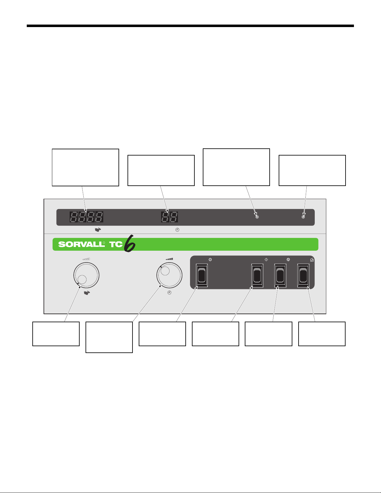
1-6. Controls, Displays,
Switches and Indicators
Figure 1-1 shows the TC6®control panel and provides a brief de-
scription for each control, display, switch and indicator. Table 1-1
(on the next page) gives a complete description.
Figure 1-1. TC6®
Controls and Indicators
R
SPEED
RPM
TIME
MIN
READY DOOR
DOORSTOPSTARTHOLD
234
567 8910
1
SPEED DISPLAY
Displaysactual rotor speed
from 0 to 6000 rpm (±1%
or 10 rpm, whichever is
greater).
DOOR INDICATOR
Blinks at end of run indi-
cating the chamber door
may be opened.
TIME DISPLAY
Displays set run time and,
duringa run, remaining run
time.
READY INDICATOR
When lit, indicates that the
chamberdoorisclosed and
latched and that the centri-
fuge is ready for operation.
DOOR SWITCH
Opens the cham-
ber door.
STOP SWITCH
Stops the centri-
fuge run.
START SWITCH
Starts the centri-
fuge run.
HOLD SWITCH
Selects a continu-
ous run.
SPEED DIAL
Sets desired rotor
speed.
TIME DIAL
Sets length of run
time up to 99 min-
utes.

Introduction and Description
SORVALLCentrifuges
1-6
Table 1-1. Description of Controls,
Displays, Switches and Indicators
SPEED display Indicates actual rotor speed from 0
to 6000 rpm (±1% or 10␣rpm, which-
ever is greater).
TIME display Indicates set run time at the begin-
ning of the run and the remaining
run time after the START switch is
pressed. In HOLD mode, two dashes
are displayed.
READY indicator light When lit, indicates that the chamber
door is closed and latched and that
the centrifuge is ready for operation.
DOOR indicator light At the end of the run this light blinks
indicating that the rotor has stopped
spinning and that the chamber door
may be opened.
SPEED dial Sets the desired rotor speed in rpm.
As indicated by the symbol, turn the
dial to the right to increase speed.
TIME dial Sets length of run time up to 99 min-
utes.
HOLD switch Selects a continuous run (two dashes
will appear in the TIME display to
indicate a run in HOLD mode).
START switch Starts the centrifuge run.
STOP switch Stops the centrifuge run.
DOOR switch At the end of a run, after the rotor
has stopped spinning and the DOOR
light blinks, this switch releases the
chamber door.
POWER switch The power switch is a rocker switch
that toggles on and off. When set to
"I", applies power to the centrifuge.
MIN
(NOT SHOWN)

Table of Contents
SORVALLCentrifuges
viii
Page
2-1. Inspection . . . . . . . . . . . . . . . . . . . . . . . . . . . . . . . . . . . . . . . . . . . . . . . . . . . . . . 2-1
2-2. Preinstallation Requirements. . . . . . . . . . . . . . . . . . . . . . . . . . . . . . . . . . . . . . 2-1
2-3. Electrical Requirements . . . . . . . . . . . . . . . . . . . . . . . . . . . . . . . . . . . . . . . . . . 2-2
2-4. Voltage Selection . . . . . . . . . . . . . . . . . . . . . . . . . . . . . . . . . . . . . . . . . . . . . . . . 2-2
2-5. Installation . . . . . . . . . . . . . . . . . . . . . . . . . . . . . . . . . . . . . . . . . . . . . . . . . . . . . 2-4
2-6. Rotor Considerations . . . . . . . . . . . . . . . . . . . . . . . . . . . . . . . . . . . . . . . . . . . . 2-5
2-7. Running Hazardous Material . . . . . . . . . . . . . . . . . . . . . . . . . . . . . . . . . . . . . 2-6
2-8. Operation . . . . . . . . . . . . . . . . . . . . . . . . . . . . . . . . . . . . . . . . . . . . . . . . . . . . . . 2-7
2-9. Emergency Sample Recovery . . . . . . . . . . . . . . . . . . . . . . . . . . . . . . . . . . . . . 2-8
Installation Checklist
Contents
Section 2. Installation and Operation

TC6®
Installation and Operation
2-1
Section 2: INSTALLATION and OPERATION
This section contains information to install and operate your SORVALLTC6®Tabletop Centrifuge.
C A U T I O N
Thecentrifugecan be dam-
aged if connected to the wrong volt-
age. Check the voltage before plug-
ging the centrifuge into any power
source. Sorvall is not responsible for
incorrect installation.
!
W A R N I N G
The TC6®weighs 70 lbs.
Refer to the unpacking instructions
for proper care when lifting and in-
stalling the centrifuge. Failure to use
proper lifting techniques can result in
personal injury and/or possible dam-
age to the centrifuge.
C A U T I O N
Do not lift the centrifuge by
the front panel or the door. To do so
can result in damage to these parts.
!
2-1. Inspection
When you receive your centrifuge, carefully inspect it for any signs
of shipping damage. If you find damage, report it immediately to
the transportation company and file a damage claim, then notify
Sorvall.
Check the parts received with the centrifuge against the shipping
list; if any parts are missing, contact Sorvall (see office list in back of
manual).
2-2.␣ Preinstallation Require-
ments
The TC6®centrifuge is ordered for a specific voltage. The nameplate
on the back of the centrifuge tells the voltage ordered. Before using
the TC6®, be sure the proper operating voltage and corresponding
fuse is selected. If required (for instruments serial number 9501733
and below), the voltage setting and fuses can be changed (refer to
page 2-2, paragraph 2-4, Voltage Selection for procedure to change
the voltage).
Other preinstallation requirements include:
• providing a flat, level surface to support the weight of the
centrifuge (31 kg; 70 lbs),
• allowing adequate space for proper air circulation (5 cm;
2␣inches),
• allowing for the proper height clearance to open the chamber
door (78.7 cm; 31.0 inches); and
• providing the proper electrical requirements.
!

Installation and Operation
SORVALLCentrifuges
2-2
2-3. Electrical Requirements
The centrifuge has specific power requirements and must be
connected to the correct power supply for proper performance. The
nameplate on the back of the centrifuge specifies one of the following:
100 - 120 Vac, 60 Hz, single phase, 3/15 amps*
220 - 240 Vac, 50 Hz, single phase, 2 amp*
Check line voltage with a voltmeter. Then, verify that the voltage
indicated on the nameplate on the back of the centrifuge agrees
with the measured line voltage.
If the line voltage is beyond the ±10% tolerance (of nominal) given,
the result can be variations in the performance specifications and
damage to the centrifuge.
The power cord has a keyed plug that inserts into a receptacle at the
back of the centrifuge. The other end of the power cord has a three-
prong molded cap with a ground pin and parallel blades. (60 Hz
instruments require receptacle NEMA5-15R and 50 Hz instruments
require NEMA 6-15 R.).
For connection to other receptacles, the power cord may have to be
replaced. Follow local electrical regulations.
Check that the gound lug of the electrical plug is properly grounded
and is shorted to the frame of the centrifuge.
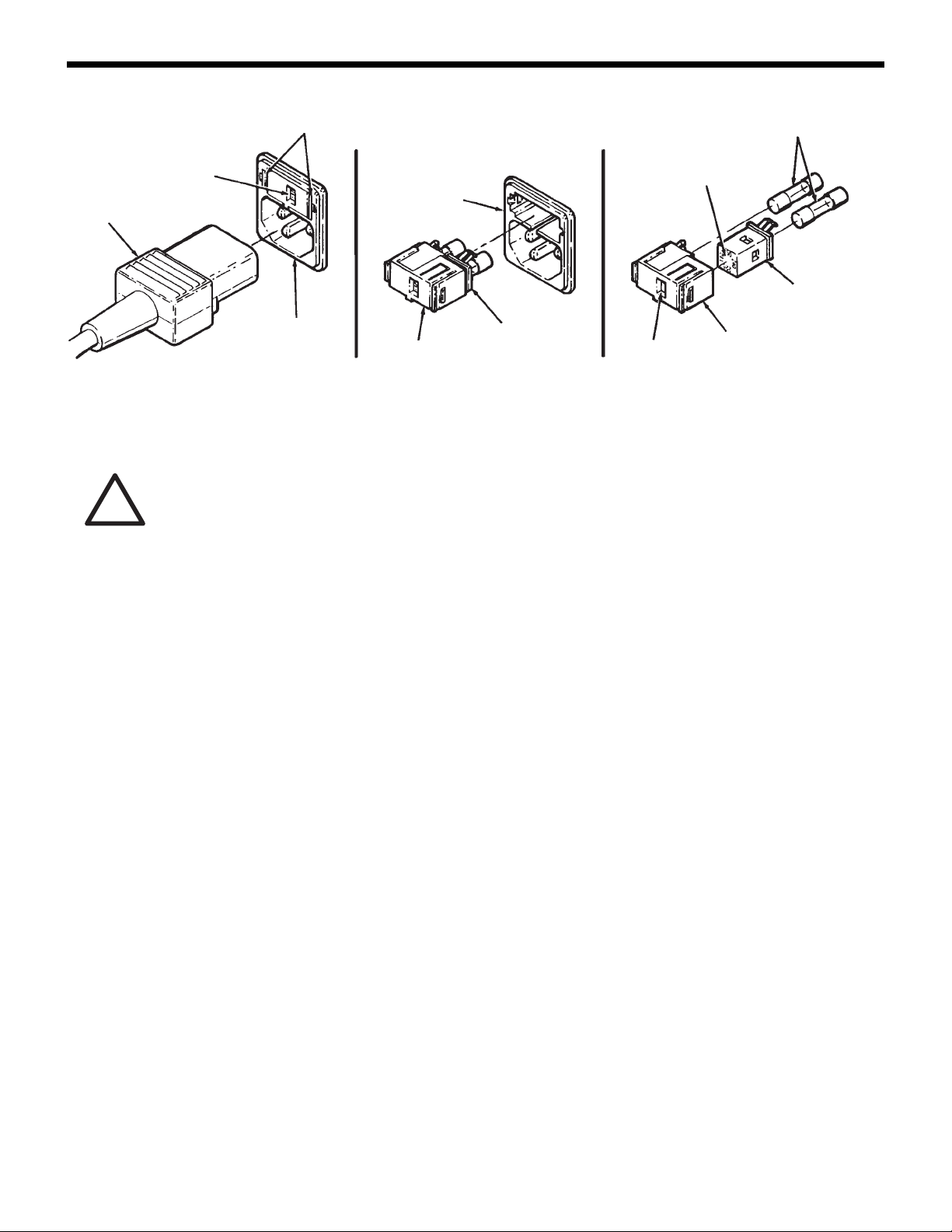
2-4. Voltage Selection
(SN 9501733 and Below)
The voltage is set by the voltage selector (in the fuse block) located
in the power connector on the back of the TC6®(refer to figure 2-1
for SN 9501733 and below). The current voltage setting (100, 110**,
220, or 240) is displayed in the window of the fuse block.
To change the voltage:
1. Unplug the power cord from the wall receptacle and from the
power connector.
2. Squeeze the two tabs located on either side of the fuse block and
carefully remove the fuse block from the power connector.
NOTE
Voltage can only be changed on instruments with serial
numbers 9501733 and below. Instruments with serial
numbers 9501734 and above must be ordered prewired
for specific voltages.
!
C A U T I O N
If the power cord is
connected to the wrong voltage, it
can cause damage to the centrifuge.
Check the voltage listed on the
nameplatebeforeplugging the power
cord into the power source. Sorvall is
not responsible for incorrect
installation.
*CSA and UL Certified.
**For 120 V operation, the voltage selector is set to 110.
TC6®
Installation and Operation
2-3
POWER
CORD
SELECTED
VOLTAGE
WINDOW
TABS
POWER
CONNECTOR
POWER
CONNECTOR
FUSE
BLOCK
FUSE
BLOCK
VOLTAGE
SELECTOR
VOLTAGE
SELECTOR
VOLTAGE
WINDOW
SELECTABLE
VOLTAGES
FUSES
Figure 2-1. Voltage Selection (SN 9501733 and below)
3. Gently pull the voltage selector from the fuse block.
4. Rotate the voltage selector until the desired voltage is aligned
with the window in the fuse block. Then, reinstall the voltage
selector into the fuse block.
5. Check that proper fuses are installed. Fuses are Type T, 250 V,
but change amperage rating depending on the voltage selected:
•100 or 110 setting requires two 3.15-amp fuses, (PN 91428),
•220 or 240 setting requires two 2-amp fuses, (PN 91203).
Change fuses if necessary.
6. Reinstall the fuse block into the power connector and plug in
the centrifuge power cord.
NOTE
If the voltage was changed from 100-110 setting to 220-
240 setting, a different power cord is required.
!
C A U T I O N
Whenchangingthe voltage
setting, be sure that the voltage
selectorisinstalled sothat the voltage
displayed in the voltage window
matches the intended input voltage.
Also, be sure that the proper fuses
have been installed, and that you are
using the proper power cord.
Incorrect installation can result in
damage to the centrifuge. Sorvall is
not responsible for incorrect
installation.

Installation and Operation
SORVALLCentrifuges
2-4
2-5. Installation
To install the centrifuge:
1. Place the centrifuge on a sturdy bench or work table that will
support its weight, leaving space for sample preparation. Be
sure to leave a minimum clearance of 10 cm (4 inches) on all
sides for proper air circulation.
2. Make sure the centrifuge is level.
3. Make sure the centifuge is set for the proper voltage (see page
2-3, Voltage Selection).
4. Make sure the power switch is set to "O" (OFF position).
5. Insert the universal keyed end of the power cord into the power
connector at the back of the centrifuge and the other end into a
wall receptacle. The centrifuge is now ready for use.
2-6. Rotor Considerations
a. Rotor Temperature
Centrifugation creates an increase in rotor temperature. The increase
in temperature is caused by variables including rotor speed, length
of the run, and the type of rotor.
Air flow through the TC6®Centrifuge is designed to minimize the
increase in rotor temperature. Air enters through the air vent in the
front panel and exits through the fan vent located at the back of the
centrifuge.
When running temperature-sensitive material, a trial run is
recommended.
b. Rotor Installation, Loading and Balancing
Before placing the rotor on the drive spindle, make sure that there
are no loose objects inside the rotor chamber; for example, clips,
tubing, tape, or labels, and that the rotor centerhole and drive
spindle are clean and free of nicks and scratches. Wipe these surfaces
before each use.
Gently place the rotor body on the tapered spindle of the centrifuge,
aligning the shaft pin with the slots in the rotor. Secure the rotor to
the drive spindle by turning the rotor locking knob clockwise.
C A U T I O N
Do not lift the centrifuge by
the front panel or the chamber door.
To do so can result in damage to
these parts.
If the power cord is connected to the
wrong voltage, it can cause damage
to the centrifuge. Check the voltage
listed on the nameplate before
plugging the power cord into the
power source. Sorvall is not
responsible for incorrect installation.
Do not operate the centrifuge without
making sure the rotor is properly
balanced. Also, when installing a
rotor, carefully place it on the
centrifuge drive spindle. The
centrifuge spindle bearings can be
damaged if rotor is dropped on the
drive spindle.
!
W A R N I N G
Blocking the air flow enter-
ing and/or exiting the TC6®centri-
fuge will cause an increase in tem-
peraturewithin therotor chamber.The
temperatureincreasecan temporarily
distort non-metal surfaces allowing
particles to exit the rotor chamber
resultingin personalinjuryand/orcen-
trifuge damage should tube break-
age or rotor failure occur.
When loading the rotor, be sure not
toexceedthemaximumcompartment
mass of the rotor (see the individual
rotorinstructionmanual). If maximum
compartment mass is exceeded,
maximum rotor speed must be
lowered as described in the rotor
instruction manual, Compartment
Loads in Excess of Design Mass.
Failureto dosocancauserotor failure
which could result in personal injury
and/or centrifuge damage.
!

TC6®
Installation and Operation
2-5
NOTE
The rotor locking knob cannot be tightened if the rotor is
not properly installed on the drive spindle.
Refer to the rotor instruction manual for bucket loading and balanc-
ing procedures as well as information regarding the selection and
use of tubes, bottles, and adapters.
2-7. Running Hazardous
Material
Because the centrifuge chamber of the TC6®is not designed for
biocontainment, some vapors or aerosols released from uncapped,
leaking or broken tubes may leak from the chamber during operation.
Once a run is completed and the chamber door is opened, the
vapors or aerosols which have concentrated in the chamber will be
released into the laboratory area. For this reason, when materials
which are radioactive, pathogenic, toxic, or otherwise hazardous in
nature are to be run, the centrifuge should be located in a biohazard
safety enclosure and operated using all appropriate safety
precautions. If desired, we recommend the use of sealed bucket
assembly (Catalog No. 78016) to offer increased protection from
contamination from uncapped, leaking or broken tubes.
NOTE
The sealed bucket assemblies (Catalog No. 78016) are
designed to seal tightly during operation and meet the
British Standards BS 4402:1982 Appendix D. They have
been tested at the Public Health Laboratory Service
Centre for Applied Microbiology and Research, Porton
Down, United Kingdom, and found suitable for use with
materials up to ACDP Category 3.
Use appropriate decontamination procedures should exposure to
any hazardous material occur. Read paragraph 1-2, page 1-1 for the
procedure to follow if a centrifuge or rotor that has been used with
a hazardous material must be returned to our service facilities for
repair.
!
C A U T I O N
Do not operate the centri-
fuge without making sure the rotor is
properlybalanced.Also, when install-
ing a rotor,
carefully
place it on the
centrifuge drive spindle. The centri-
fuge drive spindle bearings can be
damaged if the rotor is dropped on
the drive spindle.
W A R N I N G
When using radioactive,
toxic, or pathogenic materials, be
aware of all characteristics of the
materialsandthe hazards associated
with them in the event leakage oc-
curs during centrifugation. If leakage
doesoccur,neither the centrifuge nor
the rotor can protect you from par-
ticles dispersed in the air. To protect
yourself, we recommend additional
precautions be taken to prevent ex-
posure to these materials, for ex-
ample, use of controlled ventilation
or isolation areas.
Always be aware of the possibility of
contamination when using radioac-
tive, toxic, or pathogenic materials.
Take all necessary precautions and
useappropriatedecontamination pro-
cedures if exposure occurs.
Theuse ofsealedrotors,bucketsand/
or sample containers will provide in-
creased protection from contamina-
tion during routine operation. How-
ever, these items will not guarantee
contamination protection from acci-
dents resulting in damage to the rotor
orbuckets.Do notrunhazardous ma-
terial in the centrifuge unless it is
placed in a biohazard enclosure and
operatedusing appropriatesafety pre-
cautions.
!
Table of contents
Other Sorvall Laboratory Equipment manuals


Popular Laboratory Equipment manuals by other brands


SPEX SamplePrep
SPEX SamplePrep Genomax 2050 Operation manual

TSI Instruments
TSI Instruments 3775 Operation and service manual

Agilent Technologies
Agilent Technologies G1574A installation guide

Flight Dental Systems
Flight Dental Systems Clave 23+ instruction manual

Milestone
Milestone HistoDream M Operator's manual

Agilent Technologies
Agilent Technologies G1364B user guide


