Sorvall Cellwasher 2 User manual

Cellwasher 2 Service SORVALL®lnstrumentS
This manual is a guide for service of the
SORVALL® Cellwasher 2 Cell Washing System
Data herein has been verified and validated and is believed adequate for the intended use
of the instrument. If the instrument or procedures are used for purposes over and above
the capabilities specified herein, confirmation of their validity and suitability should be
obtained, otherwise, DuPont does not guarantee results and assumes no obligation or
liability. This publication is not a license to operate under, nor a recommendation to
Infringe upon, any process patents.
This service manual is intended as a service aid. While the manual is kept current and
includes information regarding significant design changes, specific designs may still vary
from instrument to instrument.
This service manual is intended for use only by service personnel who have been trained
by DuPont. Due to the high electrical potential in this centrifuge, untrained individuals
must not attempt any of the procedures in this service manual.
NOTES, CAUTIONS, and WARNINGS within the text of this manual are used to emphasize
important and critical instructions:
WARNING A Warning informs the operator of a hazard or an unsafe practice that could
result in personal injury, affect the operator's health, or contaminate the
environment.
CAUTION A Caution informs the operator of an unsafe practice that could result in
damage of equipment.
NOTE A Note highlights essential information.
Ili^^^^^^^^^^^^^^^^^^^^^^^^^^ ! ' ' ^^^NG';'^'^'6'!;''1:^;":,!^
When using radioactive, toxic, or pathogenic material, be aware of all .:
characteristics of the material and the hazards associated with it. In the .
I?''lew^^^ltt'lii^^
rotor can protect you from the particles dispersed into the air. To protect
^['licit^
^'eiiilitiil^^
!:::^::;^3(m£te::NOTS!USi:iM^^
^'^oi'iilltBiiivl'ti^^
ii

Sorvall® Instruments Cellwashcr 2 Service
Table of Contents
Paragraph Page
1-1.
1-2.
1-3.
1-4.
2-1.
2-2.
2-3.
2-4.
2-5.
2-6.
3-1.
3-2.
3-3.
4-1.
4-2.
4-3.
4-4.
4-5.
4-6.
4-7.
4-8.
4-9.
4-10.
Section I. INTRODUCTION
Intended Users .................................... 1-1
Warnings and Cautions ..............................1-1
Service Decontamination Policy. ....................... 1-1
Warranty Responsibility ............................. 1-2
Section 2.
DESCRIPTION, INSTALLATION and OPERATION
Description of the Cellwasher 2 ........................ 2-1
Cellwasher 2 Specifications ........................... 2-1
Installation Information. ............................. 2-2
Cellwasher 2 Operation .............................. 2-10
Emergency Sample Recovery .......................... 2-17
Condensed Operating Instructions ..................... 2-18
APPENDED: Condensed Operating Instructions ........... 2-19s
Section 3. MAINTENANCE
Inspection and Cleaning ............................. 3-1
Tubing Replacement ................................ 3-5
Cellwasher 2 Preventive Maintenance Procedure ........... 3-5
APPENDED: Preventive Maintenance Checklist ........... 3-9
Section 4. MECHANICAL THEORY
Controls ......................................... 4-1
Flexible Drive Mounting ............................. 4-1
Cabinet ......................................... 4-1
Air Flow ......................................... 4-1
Motor ........................................... 4-1
Safety Latch ...................................... 4-1
Saline Pump System ................................ 4-2
Flow Detector ..................................... 4-2
Flow Control Clamp ................................ 4-2
Motor Antirotation Clutch ............................ 4-2
in
Rev. 11/90

Cellwashcr 2 Service Sorvall® Instruments
Table of Contents (continued)
Paragraph Page
5-1.
5-2.
5-3.
5-4.
5-5.
6-1.
6-2.
6-3.
6-4.
8-1.
8-2.
8-3.
8-4.
8-5.
8-6.
8-7.
8-8.
8-9.
8-10.
8-11.
Section 5. ELECTRICAL THEORY
System Description ................................. 5-1
Touch Switch Panel. ................................ 5-31
Interface PC Board ................................. 5-31
Microcomputer PC Board ............................ 5-37
Electronics Module ................................. 5-50
Section 6. APPLICATIONS
Cellwasher 2 Application ............................. 6-1
Compatibility Testing ............................... 6-1
Cellwasher 2 Washing Cycle .......................... 6-2
Glossary of Blood Banking Terms ...................... 6-6
Section 7. TROUBLESHOOTING
Section 8. REPAIR and REPLACEMENT PROCEDURES
Base Plate Removal................................. 8-1
Cabinet Removal................................... 8-1
Front Panel Removal ................................ 8-2
Power Switch Replacement ........................... 8-3
Pump Replacement................................. 8-3
Pump Motor Replacement ............................ 8-3
Flow Detector Replacement........................... 8-4
Motor Replacement................................. 8-4
Interface Printed Circuit
Board Replacement................................ 8-4
Microcomputer Printed Circuit
Board Replacement................................ 8-5
Fuse Replacement.................................. 8-5
IV
Rev. 11/90
Son/all® Instruments Cellwasher 2 Service
Table of Contents (continued)
Paragraph Page
Section 9. KIT INSTRUCTIONS
9-1.
9-2.
9-3.
9-4.
9-5.
9-6.
9-7.
Figure
2-1.
2-2.
2-3.
2-4.
2-5.
3-1.
3-2.
5-1.
5-2.
5-3.
5-4.
5-5.
5-6.
Tubing Replacement Kit (PN 04632) .................... 9-2
Collector Seal Replacement Kit (PN 04353) ............... 9-9
Retainer Ring Replacement Kit (PN 12850) ............... 9-12
Lid Latch Assembly Replacement
Kit (PN 12792).................................... 9-14
Saline Shield Kit (PN 12811) .......................... 9-19
Triac-Interface Printed Circuit Board
Replacement Kit (PN 12816) ......................... 9-20
Adapter Clip Installation Kit (PN 04330) ................. 9-23
Section 10. ILLUSTRATED PARTS LIST
List of Illustrations
Page
Cellwasher 2 Tubing Diagram ......................... 2-4
Stainless Steel Rotating Bowl Installation ................ 2-2
Distributor Installation .............................. 2-9
Cellwasher 2 Controls and Indicators ................... 2-10
Location of Mechanical Override ....................... 2-18
Exploded View, Collecting Ring Assembly
(SN 8702302 and higher) ........................... 3-3
Exploded View, Collecting Ring Assembly
(SN 8702301 and lower) ............................ 3-5
System Schematic, Cellwasher 2 ....................... 5-3
Wiring Diagram, Cellwasher 2 ......................... 5-5
Microcomputer PC Board ............................ 5-7
Schematic, Microcomputer PC Board ................... 5-11
Triac-Interface PC Board (PN 04834 Revision 0,
SN 8503865 and higher) ............................ 5-16
Schematic, Triac-Interface PC Board (PN 04537
Revision 2, SN 8503865 and higher) ................... 5-17
v
Rev. 11/90
Cellwasher 2 Service SORVALL®lnstrumentS
List of Illustrations (continued)
Figure Page
5-10. Schematic, Onterface PC Board (PN 04537
Revision 1, SN 8503864 and below) ........................ .5-25
5-11. Cellwasher 2 Automatic Wash Sequence ...................... .5-30
5-12. Indicator Current Path ................................... .5-31
5-13. Schematic, Touch Switch Panel ............................ .5-33
5-14. Interface PC Board, Test Set-Up #1 .......................... .5-35
5-15. Interface PC Board, Test Set-Up #2 .......................... .5r36
5-16. Microcomputer Board Input/Output Configuration .............. .5-38
5-17. Microcomputer Scan Routine .............................. .5-39
5-18. Creating New Input/Output Formats ........................ .5-41
5-19. Digital Time Display Segments ............................. .5-42
5-20. Starting in Manual (High or Low) Mode, Logic Flow Chart ......... .5-47
5-21. Starting from Check Mode, Logic Flow Chart ................... .5-48
5-22. Starting in Auto Mode, Logic Flow Chart ...................... .5-49
7-1. Location of Decant Coil and Drive Ring ....................... .7-7
7-2. Location of Lift Plate Ring ................................. .7-7
9-1. Tubing Diagram: Parts Location ............................ .9-2
9-2. Adjustable Tubing Clamp Location .......................... .9-6
9-3. Adjustable Tubing Clamp ................................. .9-8
9-4. CW-1 Collecting Ring Assembly Exploded View ................. .9-10
9-5. Cellwasher 2 Collecting Ring Assembly Exploded View ........... .9-11
9-6. Cabinet Machine Drawing ................................. .9-17
9-7. Adhesive Location ....................................... .9-20
9-8. Installing an Adapter Clip ................................. .9-24
10-1. Cellwasher 2 Assembly .................................... 10-5
10-2. Chassis and Component Assembly ........................... 10-11
10-3. Drive Motor Assembly ..................................... 10-15
List of Tables
Table Page
2-1. Parts Location: Tubing Diagram ............................ .2-4
2-2. Cellwasher 2 Controls and Indicators ........................ .2-9
5-1. Component Identification, Microcomputer PC Board .............. 5-8
5-2. Component Identification, Triac-Interface PC Board
(PN 04834, Revision 0, SN 8503865 and higher) ............... .5-15
5-3. Triac PC Board Component Identification ..................... .5-19
5-4. Component Identification, Interface PC Board
(PN 04536, Revision 2, SN 8503864 and below) ............... .5-23
5-5. Automatic Wash Sequence ................................ .5-30
5-6. Microcomputer Scan Map ................................. .5-40
5-7. Electronics Control System ................................ .5-43
vi Rev. 4/96

SORVALL® Instruments Cellwashcr 2 Service
List of Tables (continued)
Table Page
6-1. Applications Troubleshooting Chart: False Negative Results ........ 6-3
6-2. Applications Troubleshooting Chart: False Positive Results ........ .6-4
6-3. Applications Troubleshooting Chart: Inconsistent Reaction
Strength ............................................. .6-5
7-1. Troubleshooting Chart: Drive Motor ......................... .7-2
7-2. Troubleshooting Chart: Power .............................. .7-3
7-3. Troubleshooting Chart: Saline Fill ........................... .7-4
7-4. Troubleshooting Chart: Decant .............................. 7-5
7-5. Troubleshooting Chart: Lid Latch ........................... .7-6
10-1. Suggested Spare Parts, CeUwasher 2 ......................... 10-2
10-2. CeUwasher 2 Assembly .................................... 10-3
10-3. Chassis and Component Assembly ........................... 10-7
10-4. Drive Motor Assembly ..................................... 10-13
Rev. n/90 vii/viii

SORVALL® Instruments Cellwasher 2 Service
Section 1. INTRODUCTION
This manual is a service guide for the Sorvall Cellwasher 2 Cellwashing
System. It contains descriptive information; preventive maintenance
procedures; mechanical and electrical theories of operation; applications
information; a troubleshooting guide; field procedures for repairs and
replacements; and an illustrated parts list for ordering replacement
parts.
1-1. Intended Users
This manual has been written for qualified service personnel who are
familiar with factory methods for performing repairs, adjustments and
calibrations. While the descriptive information and operating
procedures contained in this manual are useful to the cellwasher
operator, the replacement and calibration procedures (especially those
involving electrical circuitry) should be performed only by qualified
service personnel.
1-2. Warnings and Cautions
Warnings and cautions appear throughout the manual. Service personnel
are expected to be familiar with their meaning (see page ii) and to
read them before servicing an instrument.
1-3. Service Decontamination Policy
———————————————————————— WARNING ————————————————————————
Either biological or radioactive contamination of the
instrument and/or rotor can occur because of the samples
likely to be processed. Always be aware of this
possibility and take normal precautions. Use appropriate
decontamination procedures should exposure occur.
If an instrument or rotor that has been used with biohazardous material
requires servicing by DuPont personnel, either at the customer's
laboratory or at a DuPont facility, comply with the following procedure
to ensure the safety of DuPont personnel:
• Clean the instrument and/or rotor to be serviced of all
encrusted material, and decontaminate it prior to servicing by
the representative. There must be no radioactivity detectable
by survey equipment.
• Attach a completed Decontamination Information Certificate
(SORVALL Instruments Form No. IPDP-59) to the instrument or
rotor.
Rev. 11/90 1-1
Cellwasher 2 Service SORVALL® Instruments
If the instrument and/or rotor to be serviced does not have a
Decontamination Information Certificate attached, and in DuPont's
opinion presents a potential biohazard, the DuPont representative will
not service the equipment until proper decontamination and certification
is complete. If DuPont receives an instrument or rotor at its Service
facilities which, in DuPont's opinion is a biohazard/ the sender will
be contacted for instructions as to the disposition of the equipment.
Disposition costs will be borne by the sender.
Decontamination Information Certificates are included with these
instructions. Additional certificates are available from the local
Technical or Service Representative. In the event these certificates
are not available, a written statement certifying that the instrument
and/or rotor has been properly decontaminated and outlining the
procedures used will be acceptable.
NOTE
The Service Representative will note on the Customer
Service Repair Report if decontamination was required, and
if so, what the contaminant was and what procedure was
used. If no decontamination was required, it will be so
stated.
1-4. Warranty Responsibility
Whenever service of the instrument is attempted by anyone other than
an employee of DuPont or an authorized DuPont representative, the
individual performing the service is assuming the risk of voiding the
instrument warranty, which is as follows:
E. I. Du Pont de Nemours and Company makes no warranty of any
kind, expressed or implied, except as stated in this warranty
policy.
The Sorvall® Cellwasher 2 Cell Washing instrument and DA-12
Rotor are warranted to be free from defects in materials and
workmanship for a period of one (1) year from the date of
delivery. DuPont will, at its option, repair or replace and
return free of charge any part which is returned to its factory
within said period, transportation prepaid by user, and which
is found upon inspection to have been defective in materials
or workmanship. This warranty does not include normal wear
from use; it does not apply to any instrument or part which
has been altered by anyone other than an employee of DuPont,
nor to any instrument which has been damaged through accident,
negligence, failure to follow operating instructions, the use
of electric currents or circuits other than those specified
on the plate affixed to the instrument, misuse or abuse.
DuPont reserves the right to change, alter, modify or improve
any of its instruments without any obligation to make
corresponding changes to any instrument previously sold or
shipped.
1.2 Rev. 11/90
SORVALL® Instruments Cellwasher 2 Service
THE FOREGOING OBLIGATIONS ARE IN LIEU OF ALL OTHER OBLIGATIONS AND
LIABILITIES INCLUDING NEGLIGENCE AND ALL WARRANTIES/ OF
MERCHANTABILITY OR OTHERWISE, EXPRESSED OR IMPLIED IN FACT OR BY
LAW, AND STATE OUR ENTIRE AND EXCLUSIVE LIABILITY AND BUYER'S
EXCLUSIVE REMEDY FOR ANY CLAIM OR DAMAGES IN CONNECTION WITH THE
SALE OR FURNISHING OF GOODS OR PARTS/ THEIR DESIGN, SUITABILITY
FOR USE, INSTALLATION OR OPERATION. DUPONT WILL IN NO EVENT BE
LIABLE FOR ANY SPECIAL OR CONSEQUENTIAL DAMAGES, AND OUR LIABILITY
UNDER NO CIRCUMSTANCES WILL EXCEED THE CONTRACT PRICE FOR THE GOODS
FOR WHICH LIABILITY IS CLAIMED.
If there are any questions concerning the effect of service on the
warranty, contact the nearest representative of Sorvallo Instruments.
1-3/1-4

SORVALL® Instruments Cellwasher 2 Service
Section 2. DESCRIPTION, INSTALLATION and OPERATION
This section describes the Sorvall® Cellwasher 2 and provides speci¬
fications, installation information, and instructions for operating
the instrument.
2-1. Description of the Cellwasher 2
The SORVALL® Cellwasher 2 is designed to perform the washing phase of
the Coomb's Procedure automatically. The centrifuge and saline pump
are contained in one cabinet, with the operating controls on the front
panel.
The Cellwasher 2 is microprocessor-controlled, featuring a front panel
with sensor-touch controls and a digital timer for the wash cycle. Other
features include a saline detect system with an audible low-saline
warning and an agitate cycle that ensures complete resuspension of
cells and eliminates manual agitation.
2-2. Cellwasher 2 Specifications
Dimensions:
Width ............
Depth ............
Height, lid closed
Height, lid open .
Mass (Weight)
Electrical Requirements*:
Motor Type
Speed** for 60 Hz models:
Low
High
Decant
Speed** for 50 Hz models:
Low ...................
High ..................
Decant ................
31.8 cm (12.5 in)
35.6 cm (14.0 in)
36.8 cm (14.5 in)
57.2 cm (22.5 in)
16.4 kg (36.0 Ib)
115 V + 10%, 60 Hz, 5A
or
230 V + 10%, 50 Hz, 2A
3 speed induction
1150 to 1200 rpm
3500 to 3600 rpm
600 rpm
1450 to 1500 rpm
2950 to 3000 rpm
600 rpm
(continued)
2-1
Cellwasher 2 Service SORVALL® Instruments
Decibel .................................... 67 Db
Length of Modes:
Automatic ................................ Total cycle time 80
seconds
Manual ................................... High or low, optional,
up to 999 seconds if
timed; indefinite if
in HOLD
Tube Sizes:
Diameter ................................. 12 mm + 0.09 mm
or
10 mm + 0.09 mm*
Length ................................... 75 mm + 2 mm
Tube Material: ............................. High strength glass, such
as Pyrex® or Corex®
WARNING
Use only tubes which are guaranteed to be within the
specifications given above. If tubes outside these
specifications are used, test results will be affected,
the rotor and distributor could be damaged, and personal
injury could result.
2-3. Installation Information
a. Location
Place the Cellwasher 2 on a sturdy/ level bench or table near a sink,
drain, or waste container to receive decanted saline. The following
factors should be considered when selecting a location:
• Allow a 15 cm (6 inch) clearance behind the instrument for the
saline pump and tubing.
Allow a 61 cm (24 inch) clearance above the tabletop or bench
surface for the lid to open.
"Adapter Clips (PN 04330) are required when using 10 mm x 75 mm tubes in the DA-12 Rotor.
2-2 Rev. 11/93
SORVALL® Instruments Ccllwasher 2 Service
Drainage in the Cellwasher 2 is accomplished by gravity, so the
drain tubing must extend downward from the instrument to the
drain, sink, or waste receptacle.
The preferred location for the saline supply is either at or
above instrument level.
To obtain the best results, minimize tubing length from the
saline supply to the cellwasher.
CAUTION
Cooling air is drawn into the Cellwasher 2 from all four
sides of the base. Be sure that the entrances are not
obstructed.
If the saline supply reservoir is moved from its original location,
recheck the saline volume by priming the system as explained in
paragraph 2-4, b.
b. Electrical Requirements
The power cord for the Cellwasher 2 has a universal keyed plug that
inserts into a receptacle at the back of the instrument. The other end
must be connected to the appropriate power supply:
115 V + 10%, 60 Hz, 5A or 230 V + 10%, 50 Hz, 2.5A
as specified on the rating plate on the back of the instrument.
————————————————————— WARNING —————————————————————
The receptacle used should be a 3-wire system. If it is
not, the equipment must be grounded to earth to avoid the
possibility of electrical shock.
c. Tubing Installation
The Cellwasher 2 is shipped with the tubing already connected to the
instrument, but not installed in the peristaltic pump. To install the
tubing in the peristaltic pump, unwrap the bundle of tubing at the back
of the instrument and proceed as follows (refer to figure 2-1):
2-3

Cellwashcr 2 Service SORVALL® Instruments
1. Remove the four knurled thumbscrews from the peristaltic pump
and remove the front half of the pump housing. (Do not remove
the pump roller assembly.) Make sure that the pump rollers are
clean and move freely.
2. Turn the roller assembly so that one of the rollers is in the
11 o'clock position.
3. Without turning the rollers, place the pump tubing around the
rollers (the end with the connector should be on the left side) .
4. Pull up on the two ends of the pump tubing, and fit the tubing
into the pump housing around the rollers.
Figure 2-1. Cellwasher 2 Tubing Diagram
2-4 Rev. 4/96
SORVALL® Instruments Cellwasher 2 Service
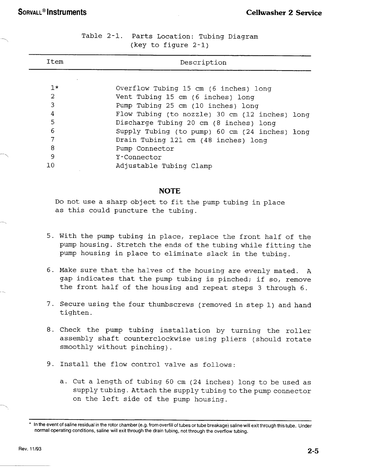
Table 2-1. Parts Location: Tubing Diagram
(key to figure 2-1)
Item Description
I*
2
3
4
5
6
7
8
9
10
Overflow Tubing 15 cm (6 inches) long
Vent Tubing 15 cm (6 inches) long
Pump Tubing 25 cm (10 inches) long
Flow Tubing (to nozzle) 30 cm (12 inches) long
Discharge Tubing 20 cm (8 inches) long
Supply Tubing (to pump) 60 cm (24 inches) long
Drain Tubing 121 cm (48 inches) long
Pump Connector
Y-Connector
Adjustable Tubing Clamp
NOTE
Do not use a sharp object to fit the pump tubing in place
as this could puncture the tubing.
5. With the pump tubing in place, replace the front half of the
pump housing. Stretch the ends of the tubing while fitting the
pump housing in place to eliminate slack in the tubing.
6. Make sure that the halves of the housing are evenly mated. A
gap indicates that the pump tubing is pinched; if so, remove
the front half of the housing and repeat steps 3 through 6.
7. Secure using the four thumbscrews (removed in step 1) and hand
tighten.
8. Check the pump tubing installation by turning the roller
assembly shaft counterclockwise using pliers (should rotate
smoothly without pinching).
9. Install the flow control valve as follows:
a. Cut a length of tubing 60 cm (24 inches) long to be used as
supply tubing. Attach the supply tubing to the pump connector
on the left side of the pump housing.
* In the event of saline residua] in the rotor chamber (e.g. from overfill of tubes or tube breakage) saline will exit through this tube. Under
normal operating conditions, saline will exit through the drain tubing, not through the overflow tubing.
Rev. 11/93 2-5

Cellwasher 2 Service SORVALL® Instruments
b. Place the valve over the supply line at a convenient point
and insert the end of the supply tubing into a saline supply
reservoir.
c. Connect the pump tubing from the right side of the pump
housing to the inlet port of the flow detector.
10.Into the adjustable tubing clamp located to the left of the
peristaltic pump, position the bottom leg of the Y-Connector
(with discharge tubing attached).
11. Holding the Y-Connector in place with one hand, fold the inner
strap over the Y-Connector/discharge tubing. Then, fold the
outer strap over the inner strap and push on the outer strap
to lock in place. You will hear a "click" when the clamp is
secured.
12 .Make sure the drain tubing flows downward to an open sink, drain,
or waste receptacle since drainage in the Cellwasher 2 is
accomplished by gravity. Use the shortest length of drain tubing
possible and make sure the tubing is positioned so there is no
upward travel to result in a "trap" for collected waste fluid.
13.Ideally, the drain tubing should be positioned so that it can
not become immersed in collected waste fluid. However, if there
is a possibility that the drain tubing will become immersed in
waste fluid, cut the drain tubing at a convenient point near
the waste receptacle and insert the Y-Connector. Always insert
a Y-Connector in the drain line when using a waste container
for discharged saline.
NOTE
The Y-Connector prevents pressure from building up in
the line due to submerged tubing or air blockage. Failure
to vent the drain tubing by installing a Y-Connector can
result in improperly decanted samples.
If the saline supply reservoir is moved from its original
location, recheck the saline volume by priming the system
as explained in paragraph 2-4, b.
14.If necessary, use additional tubing and connectors from
the Tubing Kit to supply saline and discharge waste
properly.
2-6 "s"-4/^
SORVALL® Instruments Ccllwasher 2 Service
WARNING
Saline solution from some manufacturers contains sodium
azide as a preservative. If this solution is discharged
directly down the drain, explosive azide salts may form
as the sodium azide reacts with the plumbing. Check with
your saline supplier before discharging saline from the
Cellwasher 2 into a drain.
CAUTION
All saline solutions have long term corrosive effects.
Routine cleaning and maintenance (as described in Section
3) are essential to ensure safe and efficient operation
of the Cellwasher 2.
d. DA-12 Dual Angle Rotor and Distributor Installation
1. Open the lid of the Cellwasher 2.
———————————————————— WARNING ————————————
All Sorvall® Cellwashers manufactured prior to February
1984 were supplied with a plastic rotating bowl assembly
which required annual replacement. All plastic rotating
bowl assemblies are more than one (1) year old and should
be removed from service and discarded immediately. Failure
to do so can result in damage of equipment and/or personal
injury. Replace the plastic rotating bowl assembly with
a stainless steel rotating bowl assembly (PN 12796).
NOTE
There may be one or more holes in the stainless steel
rotating bowl assembly (PN 12796). These holes are for
balancing purposes only and will not effect the perform¬
ance of the stainless steel rotating bowl.
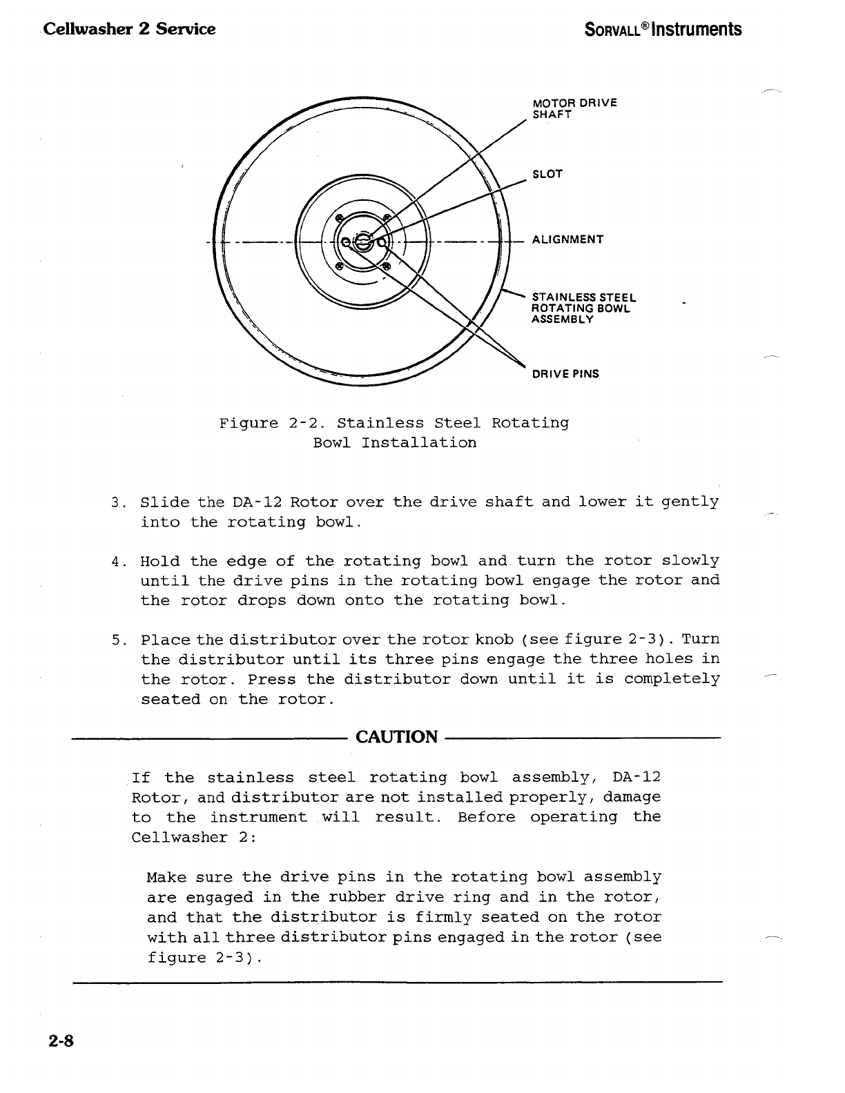
2. Position the stainless steel rotating bowl assembly over the
motor drive shaft. Align the two drive pins in the bowl with
the slot in the drive shaft (see figure 2-2). Slide the bowl
down the drive shaft until the two drive pins in the bowl engage
the rubber drive ring. Press the bowl down firmly.
2-7
Cellwasher 2 Service SORVALL® Instruments
MOTOR DRIVE
SHAFT
SLOT
ALIGNMENT
STAIN LESS STEEL
ROTATING BOWL
ASSEMBLY
DRIVE PINS
Figure 2-2. Stainless Steel Rotating
Bowl Installation
3. Slide the DA-12 Rotor over the drive shaft and lower it gently
into the rotating bowl.
4. Hold the edge of the rotating bowl and turn the rotor slowly
until the drive pins in the rotating bowl engage the rotor and
the rotor drops down onto the rotating bowl.
5. Place the distributor over the rotor knob (see figure 2-3) . Turn
the distributor until its three pins engage the three holes in
the rotor. Press the distributor down until it is completely
seated on the rotor.
CAUTION
If the stainless steel rotating bowl assembly, DA-12
Rotor, and distributor are not installed properly, damage
to the instrument will result. Before operating the
Cellwasher 2:
Make sure the drive pins in the rotating bowl assembly
are engaged in the rubber drive ring and in the rotor,
and that the distributor is firmly seated on the rotor
with all three distributor pins engaged in the rotor (see
figure 2-3).
2-8

SORVALL® Instruments Cellwasher 2 Service
DISTRIBUTOR
CANNULA
DISTRIBUTOR
PIN
ROTOR
KNOB
DUAL
ANGLE
ROTOR
Figure 2-3. Distributor Installation
e. Rotor Loading and Balancing:
The Cellwasher 2 can process any balanced load up to twelve tubes. When
using less than a full complement of tubes, place the tubes in opposing
compartments to ensure that the rotor is symmetrically balanced. The
volume of saline delivered through the distributor will be the same/¬
at the locations without tubes, saline will be centrifuged into the
basin and drained off.
WARNING
Use only tubes which are guaranteed to be within the
specifications given in paragraph 2-2. If tubes outside
these specifications are used, test results will be affected,
the rotor and distributor could be damaged, and personal
injury could result.
Rev. 11/93 2-9

Cellwasher 2 Service SORVALL® Instruments
2-4. Cellwasher 2 Operation
a. Controls and Indicators
All controls and indicators for the Cellwasher 2/ except the power
switch, are located on the front panel keyboard. The sensor-touch
controls register commands visually and/or audibly.
Power to the instrument is controlled by a switch located in the lower
right hand corner of the cellwasher, beneath the keyboard. The symbol
"1" indicates ON while the symbol "0" indicates the OFF position.
Switching the power off erases any manually programmed spin times from
the memory.
Table 2-2 describes the controls and indicators on the front panel.
Figure 2-4 shows their locations on the keyboard.
20 19 18 16 17 15 14 13
Figure 2-4. Cellwasher 2 Controls and Indicators
*LED, or light emitting diode, refers to the small amber light adjacent to the panel button.
2-10
Other Sorvall Laboratory Equipment manuals


Popular Laboratory Equipment manuals by other brands

Organomation
Organomation MICROVAP 11801 instruction manual

Topcon
Topcon Compu-Vision CV-5000 Repair manual

Heidolph
Heidolph VV Micro instruction manual

AMA Instruments
AMA Instruments The GC 5000 BTX operating manual

TQC Sheen
TQC Sheen SP7310 operating instructions

IKA
IKA RH basic 1 operating instructions


Carl Roth
Carl Roth ROTIPHORESE PROfessional Acetate Instructions for use

MixRite
MixRite 12500 user manual

Image Engineering
Image Engineering CAL3-XL user manual

JENTNER
JENTNER DIGITAL II operating instructions

Fisher Scientific
Fisher Scientific 04-978-229 instructions

Peak Scientific
Peak Scientific Precision Hydrogen installation guide