Southland OMD-501D User manual

OMD-501D
Trace Oxygen Analyzer
4045 E. Guasti Rd. #203
Ontario, CA 91761 USA
Web: www.sso2.com
Phone: 1-949-398-2879
E-mail: [email protected]
OMD-501D Manual Rev 1.3 1_2015
Instruction Manual

Table of Contents
Part 1 Introduction
Part 2 Installation
Part 3 Operation
Part 5 Annexures
Part 4 Maintenance
1.1 General Introduction
1.2 Principle of Operation - e Oxygen Sensor
1.3 OMD-501D Specications
2.1 Receiving Your New Oxygen Analyzer
2.2 Mounting the Electronics Module
2.3 Mounting the Sensor Housing
2.4 Electrical Connections
2.5 Gas Connections
2.6 Installing the Oxygen Sensor using the H3 Flow rough Sensor Housing
2.7 Installing the Oxygen Sensor using the H1 KF40 Sensor Housing
3.1 Understanding the Controls and eir Operation
3.2 Measurement Range Overview
3.3 Advanced Alarm Functions
3.4 Analog Output - 4 - 20mA
3.5 Range ID and its function
4.1 Span Calibration, using Ambient Air
4.2 Span Calibration, using Certied Span Gas
4.3 Procedure for Replacing the Sensor
4.4 Troubleshooting
5.1 Spare Parts List
5.2 Warranty
5.3 Material Safety Data Sheets
5.4 Conformance Certicate

Part 1 Introduction
1.1 General Introduction
e Southland Sensing OMD-501D Trace Oxygen Analyzer is a microprocessor based online analyzer
designed for continous measurements in a variety of applications and gas mixtures.
e analyzer was designed with the customer in mind keeping the operations simple, while still featur-
ing a fast response and rugged design. Every eort has been made to use modern industrial compo-
nents and materials which has resulted in an advanced design, excellent performance and an overall low
cost of ownership.
Southland Sensing Ltd. appreciates your business and recommends to read through the complete manu-
al to be able to get the full experience from your new oxygen analyzer.
1.2 Principle of Operation - e Oxygen Sensor
e precision electrochemical oxygen sensor used in the OMD-501D is designed and manufactured by
Southland Sensing Ltd under a strict quality proceedure.
To understand how the oxygen analyzer functions, it is important to understand a little bit of the sensor
characteristics.
e active components in the precision electrochemical oxygen sensor is the anode, cathode and aque-
ous electrolyte which is all housed in a cell body. e oxygen molecules in the application pass through
the front sensing membrane. A chemical reaction occurs and a raw electrical current is generated.
is electrical current is proportional to the amount of oxygen in the application. e analyzer than
processes this raw electronic signal, compensates for temperature and barometric pressure variations
and converts the data into a parts-per-million or percent oxygen measurement value.
Once the data is displayed in real time on the full color backlite display, the user can control their pro-
cess using the two fully adjustable alarms with a built in delay feature. or output the analog 4 - 20mA
signal to a PLC or other control system.
Precision Electrochemical Oxygen Sensor

Part 1 Introduction
1.3 OMD-501D Specications
OMD-501D Trace Oxygen Analyzer
Precision Electrochemical Sensor Technology
Large Color Display w/ User Friendly Menu
5 Standard Analysis Ranges
Auto-Ranging or Manual Range Mode
Two Adjustable Alarm Contacts w/ delay mode
Panel Mount, 1/4 DIN Enclosure Design
Applications:
“Inquiry for Application Expertise”
• InertGloveBoxSystems
• N2andO2Skids
• Laboratories&Universities
• BeverageGradeCO2Monitoring
• AirSeparationPlants
&ManyOthers
Specications:
Ranges: 0-10/100/1000ppm/1%/25%
Accuracy: +/- 1% Full Scale Range*
Display: ColorwithBacklight
Dimensions: 1/4 DIN (96 x 96 x 65mm)
Enclosure: FlushMount,ABS
Classication: GeneralPurpose
Temperature: 0 - 50 deg C
Alarms: 2AdjustableNOorNC
Power: 12-28VDCor100-240VAC
SignalOutput: 4-20mA
RangeID: 1-5VDC
Response time: T90 in 10 Seconds
Sensor: TO2-1xTraceOxygen
Sensor Life: 18—25months
Calibration: Periodically
Temperature Compensation: Integral
Recommended Flow: 0.5 - 4 SCFH
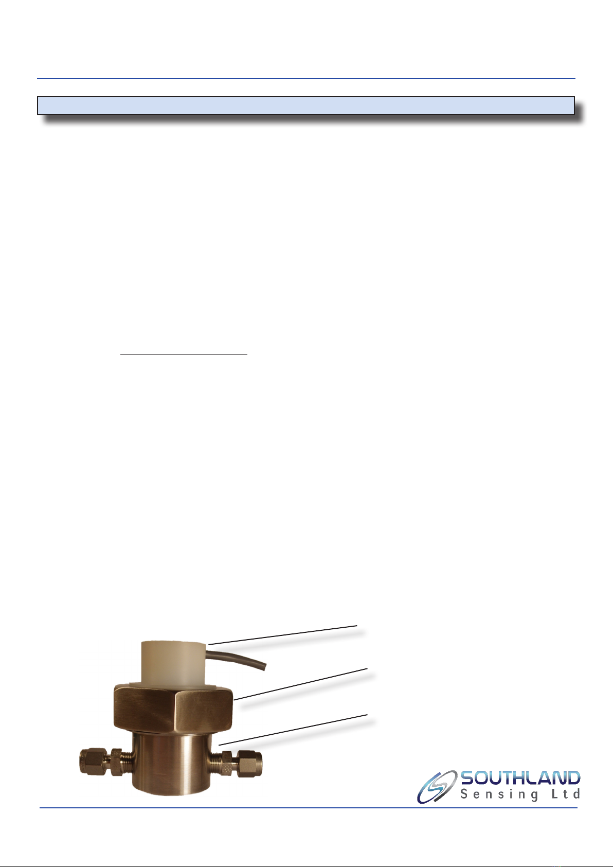
FlowCell: H3FlowCell,1/8”Swagelok
Warranty: 12MonthsSensor
Warranty: 12MonthsElectronics
*Accuracy at constant conditions
Optional Accessories:
•Optional Ranges: Fully Customizable from Factory
• H3FlowHousing1/4”SwagelokorOtherConnection
• H1DirectInstallKF-40SensorHousing
• IP66EnclosureforOutdoorInstallation
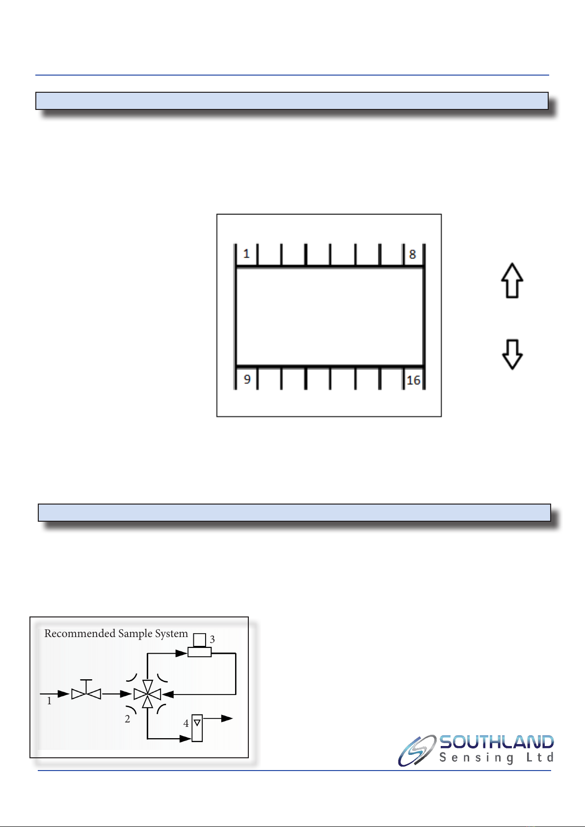
• CustomizeableSampleSystem
• TO2-2xOxygenSensorwith>0.5%CO2Present

Part 2 Installation
2.1 Receiving your New Oxygen Analyzer
As soon as you receive your new Trace Oxygen Analyzer, carefully unpack the unit and accessories and
inspect the electronics module, sensor housing for damage and also verify the oxygen sensor is present.
CAUTION: Do not open the oxygen sensor packaging at this time. It is packed
in a Nitrogen purged bag and will be damaged if le exposed to ambient air for a prolonged
period of time. It is recommended that you read through the instruction manual installation
and operation sections before attempting to open the bag the oxygen sensor is packed in. For
questions, please contact the factory.
If damage to any portion of the new analyzer is present, stop and report damage to the shipping company
as well as the factory
e analyzer is shipped with all materials needed to install and prepare the system for operation. In some
instances, added sample system components are necessary to condition the gas sample before entering
the sensor housing. Southland Sensing oers free application consultation, and we encourage you to take
advantage of our engineers and their expertise.
Remote sensor housing installation: e sensor housing can be installed up to 6 feet from the electronics
module. Further than 6 feet will cause signal degredation which can cause the unit to give erronous read-
ings. It is also important to be mindful of EMI / RFI noise interference. Protection from EMI / RFI noise is
important for accurate readings.

Part 2 Installation
2.2 Mounting the Electronics Module and Sensor Housing
Recommended Panel Cutout for OMD-501D
All menu control and local backlite display is accessible from the front of the panel. e front panel has 5
push button membrane switches, a large backlite display which includes the oxygen reading and alarm set-
points.
e OMD-501D is designed as an indoor unit. For eld installations, please refer to the NEMA4X, IP66 en-
closure option oered by Southland Sensing Ltd.
Refer to part 3 operation section of this instruction manual for more information on how to operate the con-
trols and other functions of this advanced oxygen analyzer.
For panel mount conguration, it is recom-
mended to use a panel with a cutout according
to the drawing on the le.
e OMD-501D can be mounted inside a
NEMA4X or IP66 enclosure for outdoor eld
installations.

Part 2 Installation
2.3 Mounting the Electronics Module and Sensor Housing
H3 Sensor Housing Dimensions
A precision electrochemical oxygen sensor is included as a separate item and must be installed prior to
instrument use.
CAUTION: Do not open the N2 lled oxygen sensor bag until you have thoroughly read the instruc-
tion manual and have made all gas and electrical connections. Please refer to section 2.6 or 2.7 to
reference installing the oxygen sensor into the sensor housing as well as section 4.1 and 4.2 on SPAN
Calibration.
When installing the H3 sensor housing, it is important to make sure the bottom portion of the sensor
housing is mounted at and the top portion of the sensor housing which is manufactured of nylon is
at the top. is will insure that the sensor is always face down (Screen side down, Circuit Board facing
up). is will allow any air bubbles to rise to the top and not interfer from the sensing membrane.
Oxygen Sensor Front and Rear View
e sensor housing has 4 wires and should be hard wired into the
back of the OMD-501D electronics module as follows:
Sensor (+) red wire = Pin 5
Sensor (-) black wire = Pin 6
ATC (+) white wire = Pin 7
ATC (-) Green wire = Pin 8
e sensor housing comes with a 6 foot ca-
ble. Longer cable should NOT be spliced in
as the signal can degrade and cause erronous
readings.

Part 2 Installation
2.4 Electrical Connections
Rear Imagine of Controller
TOP
BOTTOM
Pin 1: Power (+)
Pin 2: Power (-)
Pin 3: 4-20mA (+)
Pin 4: 4 - 20mA (-)
Pin 5: Sensor (+)
Pin 6: Sensor (-)
Pin 7: ATC (+)
Pin 8: ATC (-)
Pin 9: Relay Contact 1 NO
Pin 10: Relay Contact 1 COM
Pin 11: Relay Contact 1 NC
Pin 12: Relay Contact 2 NO
Pin 13: Relay Contact 2 COM
Pin 14: Relay Contact 2 NC
Pin 15: Range ID (+)
Pin 16: Range ID (-)
e OMD-501D accepts a 12 - 28VDC Power supply with a 1 amp minimum rating as standard. e maxi-
mum power consumption is 8 watts. e unit has an optional 100-240VAC power supply. Verify which
power your unit has been congured with. e unit uses a screw type terminal block for electrical connec-
tions and is located at the rear of the analyzer.
e analyzer is supplied with internal protection should the polarity of the power be connected in reverse,
it is recommended to check polarity before running power to the unit. It is also recommended to add an
external fuse to the power inlet, the analyzer does have a built in fuse, but an external fuse is suggested for
ease of access.
2.5 Gas Connections
e OMD-501D with its standard H3 ow through housing is designed for positive pressure samples and re-
quires incoming sample lines. e user is responsible for added sample system components as well as sourc-
ing a calibration gas.
It is recommended to use Stainless Steel Tubing or a low permeable plastic tubing.
•Flow rate should be between 0.5 - 3 SCFH
•Inlet pressure should be between 5 - 60 PSIG
•Analyzer should be vented to atmosphere, take precau-
tion to make sure vent does not get blocked
1
2
3
4
1 Sample Gas Inlet, goes into Flow Valve
2. Bypass valve, allows user to isolate sensor during shutdown.
3. H3 Sensor Housing
4. Flow Meter, Vent to Atmosphere
Recommended Sample System

Part 2 Installation
2.6 Installing the Oxygen Sensor using H3 Flow rough Sensor Housing
e OMD-501D can accept either a TO2-1x or TO2-2x (CO2 Applications) trace oxygen sensor. For proper
selection with your application, please view our online application guide or contact your local sales rep.
Prior to installing the sensor, it is important to make sure that the analyzer gas lines are hooked up and the
unit is ready to purge with a zero gas. Connect the zero gas line and set your ow between 0.5 - 4.0 SCFH.
To Install the Sensor:
- Remove the cell holder cap by unscrewing the stainless steel collar.
- Li up on the top of the sensor housing and set to the side.
- Inspect O’ring for cracking, replace if necessary. Always lube your Orings!
- Remove the sensor from its box. With scissors, open nitrogen purged packaging
and remove the sensor.
- Visually inspect sensor for damage, if damaged notify the factory immediately.
- Remove the shorting pins across the back of the sensor board contacts.
- Place the sensor inside the housing with the metal screen mesh facing down and
the circuit board contacts facing up.
- Return upper portion of the sensor housing to the stainless steel bottom. Tighten
collar. Hand tight is acceptable to create an airtight seal.
- Immediately start purge of zero gas.
- If the analyzer has not been calibrating, refer to section 4.1 for more information.
** Sensor should be exposed to ambient air for no more than 2 minutes. Extended periods of exposure can
damage the low end sensitivity and response time.
CAUTION: Prior to installing the oxygen sensor. Read section 4.1
on performing a span calibration.
H3 Sensor Housing Top portion of sensor housing
Stainless Steel Collar
Bottom portion of sensor housing

Part 2 Installation
2.7 Installing the Oxygen Sensor, using H1 Flow KF-40 Sensor Housing
e OMD-501D can accept either a TO2-1x or TO2-2x (CO2 Applications) trace oxygen sensor. For proper
selection with your application, please view our online application guide or contact your local sales rep.
Prior to installing the sensor, it is important to make sure that the analyzer gas lines are hooked up and the
unit is ready to purge with a zero gas. Connect the zero gas line and set your ow between 0.5 - 4.0 SCFH.
e sensor housing can also be installed in a low O2 environment with no ow such as a glove box or other
closed environment.
To Install the Sensor:
- Remove the top portion of the sensor housing by unscrewing it.
- Li up on the top of the sensor housing and set to the side.
- Inspect O’ring for cracking, replace if necessary. Always lube your Orings!
- Remove the sensor from its box. With scissors, open nitrogen purged packaging
and remove the sensor.
- Visually inspect sensor for damage, if damaged notify the factory immediately.
- Remove the shorting pins across the back of the sensor board contacts.
- Place the sensor inside the bottom housing with the metal screen mesh facing down
and the circuit board contacts facing up.
- Return upper portion of the sensor housing to the stainless steel bottom. Hand
tight should be acceptable to create an airtight seal.
- Immediately insert into glove box or other atmosphere with zero gas.
- If the analyzer has not been calibrating, refer to section 4.1 for more information.
CAUTION: Prior to installing the oxygen sensor. Read section 4.1
on performing a span calibration.
H1 Sensor Housing Top portion of sensor housing
Bottom portion of sensor housing

Part 3 Operation
3.1 Understanding the Controls and their Operation
e OMD-501D Trace Oxygen Analyzer is a feature packed unit with an easy to use menu interface.
e key attributes within the menu are the ability to select a measurement range, both manually or set
it to the auto-range mode. To calibrate the unit with a known gas, also refered to as a SPAN Calibra-
tion or SPAN CAL. To adjust, set or use the delay mode of the two onboard user programmable
Alarm Relay Contacts.
All features are programmable / selectable through the MENU bottom. e UP / DOWN arrows will
allow you to select your setpoints and the enter buttom saves the data. If you want to cancel your selec-
tion, or return to the previous screen the escape key ESC will allow you to do this. Once the unit starts
up, the following HOME Screen will appear:
Operating Range
Current Sensor Reading
Identier, Manual
or Auto Range
Alarm 1 Conguration
Alarm 2 Conguration

Part 3 Operation
3.2 Measurement Range Overview
e OMD-501D Trace Oxygen Analyzer allows the user to eld select 5 available ranges - custom
ranges are available upon request. ese ranges can be selected in manual mode meaning they are
locked into that range by the user, or they can be set to auto-range so the analyzer will adjust to give
you the best full scale resolution.
One feature to highlight when using the Auto-Range mode, the unit does have a built in 1 - 5 VDC
output Range ID feature. e Range ID uses pins 15 and 16 on the back of the unit and outputs the fol-
lowing voltage correlation:
Range 1 0 - 10 ppm 1 VDC
Range 2 0 - 100 ppm 2 VDC
Range 3 0 - 1000 ppm 3 VDC
Range 4 0 - 1% 4 VDC
Range 5 0 - 25% 5 VDC
From the HOME screen, press the MENU key and the display will indicate:
Use the UP / DOWN keys to move the cursor to allow the user
select AUTO-RANGE which will all the unit to cycle through all
ve ranges or MANUAL RANGE which will allow the user to
select a key range.
Decide which option will work best for your application.
Move the cursor button over the selection and press the
ENTER key. If you have selected the AUTO RANGE option,
it will blink for a second indicating this was selected. If you
selected the MANUAL RANGE option, the following screen
will be brought up:
Use the UP / DOWN keys and bring the * besides the range to be selected and press the ENTER key.
e selected range will blink for a second indicating the range has been selected.
Press the ESC key to move back to the previous screen.

Part 3 Operation
3.3 Advanced Alarm Functions
e OMD-501D Trace Oxygen Analyzer is equiped with 2
advanced relay contact alarms. These alarms can be configured
as normally open or normally closed, hasa delay model built-in
and can be enabled or disabled when necessary. Using the color
display, the alarms are also color coded. When not engaged,
the alarms are shown in GREEN, when engaged the alarms are
visible in RED - As seen in the picture to the right.
e alarms are rated at 5A @ 230VAC. If you are connecting to solenoid valves or a pump whose cur-
rent can uctuate greatly, it is adviseable to use a slave relay to ensure no damage occurs to the analyzer.
Setting Alarm 1 and Alarm 2 is identical to begin. Go ahead and
move the cursor to the alarm configuration you want to adjust using
the UP / DOWN keys in the analyzer MENU and press ENTER.
To adjust the value setpoint of ALARM1 simply move the cursor up /
down to select ADJUST ALARM 1 and press ENT. You will be
prompted to select a PPM or Percent value based on your alarm set
point. Press ENT once selected. From here,you can use the UP /
DOWN arrows to adjust each digit which is highlighted in red. Simply
hit the enter button to move the cursor over.
e alarm function allows the user to set the alarm to trigger the relay
contacts as a HIGH alarm or as a LOW alarm. Simply open the ALARM1
menu and SET HIGH / LOW to meet your process requirements.
e alarm has a built in DELAY mode. is is a nice feature to use if you
are working on your process and do not want to have the alarm relay
contacts trip. You will set this in a similar fashion to setting the alarm.
e DELAY mode is in minutes, so adjust the value accordingly.
e alarm can also be enabled / disabled should it be hooked up but
not required. Move the cursor using the UP / DOWN keys to the
ENABLE / DISABLE and select the ENTER key.
e alarms can function as normally open or normally closed. is
selection will be choosen when hooking up the rear wiring. It is not
completed through the soware. See the wiring diagram in section 2.4
for more information.
If any questions about the ALARM functions should arise, please contact
the factory for assistance or technical questions.

Part 3 Operation
3.4 Analog Output 4 - 20mA
** Caution: Integral 4 - 20mA converters are internally powered and do not require ex-
ternal power. DO NOT supply any voltage across these terminals as the 4 - 20mA output
will be damaged. It is also important to assure proper grounding of the external recording
device such as a PLC, DCS prior to connecting the 4 - 20mA.
When connecting the 4 - 20mA output, Pin 3 is the (+) positive side of the output. Pin 4 is the (-)
negative side of the output.
To verify the signal output of the 4 - 20mA circuit is working properly, connect an ammeter across pins
13 and 14 to verify. With no oxygen sensor connector, it should read approximately 4mA. If a sensor
is installed,you can verify the signal matches with the following formula:
Signal Output (mA) = [(Reading / Full Scale Range) x 16] + 4
For example, if we are reading 500ppm on the 1000 ppm range:
Signal Output (mA) = [(500/1000) x 16] + 4
Signal Output (mA) = 12mA
3.5 Range ID
** Caution: RANGE ID converters are internally powered and do not require external
power. DO NOT supply any voltage across these terminals as the output will be damaged.
It is also important to assure proper grounding of the external recording device.
When connecting the RANGE ID, Pin 15 is the (+) positive side of the output. Pin 16 is the (-) nega-
tive side of the output. To verify the signal output of the RANGE ID is working properly, connect a
voltmeter across pins 15 and 16 to verify. You can change the range manually in MANUAL RANGE
mode to verify:
Range 1 0 - 10 ppm 1 VDC
Range 2 0 - 100 ppm 2 VDC
Range 3 0 - 1000 ppm 3 VDC
Range 4 0 - 1% 4 VDC
Range 5 0 - 25% 5 VDC

Part 4 Maintenance
4.1 Span Calibration using Ambient Air
Calibration involves using a known span gas to match and adjust the oxygen sensor / analyzer
combo to a known value. is can be as simple as using ambient air that tends to be a constant
20.9% which is what we will focus on for section 4.1. For calibrating with a certied SPAN Gas,
please proceed to section 4.2. For a decision on which type of calibration is good for your pro-
cess consult the factory for a recommendation.
Calibration using Ambient Air:
If using ambient air to calibrate the sensor, it is recommended to read
through the calibration procedure prior to performing an air calibration
to make sure all instructions are understood. Consult the factory if any
questions arise.
If the sensor is already installed in the sensor housing, you will need to
connect the gas samples line as noted in section 2.5 or expose the sensor
to ambient air which is typically 20.9%. If using the H3 ow through
sensor housing, you can open up the housing and with two ngers, hold
the sensor to the top portion of the housing, making sure the sensor
contacts are rmly touching the gold pogo pins on the housing. e H1
sensor housing alread has a hole at the bottom of the sensor that exposes
the sensing surface to ambient air.
Let the reading stabilize for about 45 seconds and then proceed to the
following steps in the OMD-501D menu:
SPAN calibration: To Calibrate the indicator, press MENU key
Use UP/DOWN keys to bring * besides the option
SPAN CAL and press ENTER key:
SPAN CALIBRATION: To calibrate the analyzer, press MENU key
use UP / DOWN keys to bring the cursor to select the SPAN
CALIBRATION selection and press ENTER. Select the PERCENT range
e cursor will show RED next to the digit that can be edited. Use the UP
/ DOWN key to set the required value. You can shi to the next digit
by pressing the ENTER key. For example, if the current reading is 22.0%
and you need to set it to 20.9%, Using the UP and DOWN key to adjust the
value and than the enter key to toggle to the next digit. A nal ENTER is
needed to save the value and change the display.
Once ENTER has been pressed, the display will show “PASSED” or “FAILED”. If passed,
promptly put the sensor into a zero or low ppm O2 gas. is will help extend the life of the sen-
sor and speed up the response time. Sensor should be exposed to
ambient air for less than 4 minutes. If failed, repeat calibration steps.

Part 4 Maintenance
4.2 Span Calibration using a Certied Span Gas
Calibration involves using a known span gas to match and adjust the oxygen sensor / analyzer
combo to a known value. is can be as simple as using ambient air that tends to be a constant
20.9% or a bottle of certied span gas from your local air separation company. For this section,
we will focus on using a certied span gas from your local air separation company. When using
a certied bottle, it is recommended to get a span gas equal to 90% of the range you want to use.
If you are measuring in the 0 - 1000ppm range, a 900 ppm N2 / balance O2 would be idea.
For a decision on which type of calibration is good for your process, consult the factory for a
recommendation.
Calibration using Certied Span Gas:
It is recommended to read through the calibration prior to performing
an air calibration to ensure all instructions are understood. Consult
the factory if any questions arise.
Note: For a new sensor, purging with a zero gas for 4 - 6 hours will help
the low end stability and response.
Connect the gas sample line and set the pressure / ow per section 2.5
of the users manual.
Once the gas is owing, let the reading stabilize for about 2 - 5 minutes
and then proceed.
SPAN CALIBRATION: To calibrate the indicator, press MENU key
Use UP/DOWN keys to bring cursor besides the option SPAN
CALIBRATION and press the ENTER key.
Select PPM or PERCENT concentration.
Edit the digit in RED by using the UP / DOWN key. You can shi to
the next digit by pressing the ENTER key. For example, if the current
reading is 495ppm, you will need to set it to 500 ppm, which is our
arbitrary span calibration value (500pp O2 balance N2).
Once ENTER has been pressed, the display will show “PASSED” or
“FAILED”. If passed, promptly put the sensor in a zero or low oxygen
gas. is will help extend the life of the sensor and speed of response.
If failed, repeat calibration steps or consult the factory.
e sensor should be exposed to ambient air for less than 4 minutes.

Part 4 Maintenance
4.3 Procedure for Replacing the Oxygen Sensor
Oxygen Sensor Replacement:
e characteristics of a precision electrochemical fuel cell are similar to those of a battery. ey both
provide an output that is nearly constant throughout their usefule life and simply fall of sharply to-
wards zero at the end.
If the process sample that is being analyzed is in the low range (0 - 10ppm) of oxygen concentration,
cell failure will be indicated by the inability to properly calibrate the analyzer. e user will also nd
that very little adjustment of the span calibration feature will be necessary to keep the analyzer in cali-
bration during the sensors useful life. If a large adjustment is needed to calibrate the unit, or calibra-
tion cannot be reached, the sensor should immediately be replaced.
** Note, make sure to read section 2.6 “Installing the Oxygen Sensor” before replacing the sensor.
No tools are required to replace the sensor. Simply unscrew (Counter-Clockwise) the collar (H3 ow
through sensor housing) or top portion (H1 KF-40 sensor housing). Once free, open the top portion
of the sensor housing exposing the old oxygen sensor. Remove the old oxygen sensor, disposing like
you would a lead-acid battery in accordance with your local regulations.
Remove the new sensor from its package and remove the shorting strips. Place the sensor screen side
down in the sensor housing with the copper circuit board pointed up. Proceed to re-connect the collar
(H3 ow through sensor housing) or simply screw back on the top portion (H1 KF-40 Housing).
Aer the sensor has been replaced, proceed to the Span Calibration section and purge with inert gas.
** Trace oxygen sensor should not be exposed to ambient air for more than a few minutes or their re-
sponse time and expected life will be adversely aected.
4.4 Troubleshooting
For troubleshooting and advanced maintenance techniques, please contact your factory representative
for assistance.
Ph: 1-949-398-2879

Part 5 Annexures
5.3 Material Safety Data Sheet (MSDS)
Product Identication
Product Name Oxygen Sensor Series – PO2, TO2 series
Synonyms Precision Electrochemical Sensor
Manufacturer Southland Sensing Ltd, 848 North Rainbow Blvd. Las Vegas, NV 89107 USA
Emergency Phone Number 1-949-398-2879
Preparation / Revision Date April 23rd, 2012
Notes Oxygen sensors are sealed, contain protective coverings and, in normal conditions, do not
present a health hazard. Information applies to electrolyte unless otherwise noted.
Specic Generic Ingredients
Carcinogens at levels > 0.1% None
Others at levels > 1.0% Potassium Hydroxide or Acetic Acid, Lead
CAS Number Potassium Hydroxide = KOH 1310-58-3 or Acetic Acid = 64-19-7, Lead = Pb 7439-92-1
General Requirements
Use Potassium Hydroxide or Acetic Acid - electrolyte, Lead - anode
Handling Rubber or latex gloves, safety glasses
Storage Indenitely
Physical Properties
Boiling Point Range KOH = 100 to 115 C or Acetic Acid = 100 to 117 C
Melting Point Range KOH -10 to 0 C or Acetic Acid – NA, Lead 327 C
Freezing Point KOH = -40 to -10 C or Acetic Acid = -40 to -10 C
Molecular Weight KOH = 56 or Acetic Acid – NA, Lead = 207
Specic Gravity KOH = 1.09 @ 20 C, Acetic Acid = 1.05 @ 20 C
Vapor Pressure KOH = NA or Acetic Acid = 11.4 @ 20 C
Vapor Density KOH – NA or Acetic Acid = 2.07
pH KOH > 14 or Acetic Acid = 2-3
Solubility in H2O Complete
% Volatiles by Volume None
Evaporation Rate Similar to water
Appearance and Odor Aqueous solutions: KOH = Colorless, odorless or Acetic Acid = Colorless, vinegar-like
odor
Fire and Explosion Data
Flash and Fire Points Not applicable
Flammable Limits Not ammable
Extinguishing Method Not applicable
Special Fire Fighting Procedures Not applicable
Unusual Fire and Explosion Hazards Not applicable

Part 5 Annexures
5.3 Cont. Material Safety Data Sheet (MSDS)
Reactivity Data
Stability Stable
Conditions Contributing to Instability None
Incompatibility KOH = Avoid contact with strong acids or Acetic Acid = Avoid contact with
strong bases
Hazardous Decomposition Products KOH = None or Acetic Acid = Emits toxic fumes when heated
Conditions to Avoid KOH = None or Acetic Acid = Heat
Spill or Leak
Steps if material is released Sensor is packaged in a sealed plastic bag, check the sensor inside for electrolyte
leakage. If the sensor leaks inside the plastic bag or inside an analyzer sensor
housing, do not remove it without rubber or latex gloves and safety glasses and a
source of water. Flush or wipe all surfaces repeatedly with water or wet paper
towel (fresh each time).
Disposal In accordance with federal, state and local regulations.
Health Hazard Information
Primary Route(s) of Entry Ingestion, eye and skin contact
Exposure Limits Potassium Hydroxide - ACGIH TLV 2 mg/cubic meter or Acetic Acid - ACGIH
TLV / OSHA PEL 10 ppm (TWA), Lead - OSHA PEL .05 mg/cubic meter
Ingestion Electrolyte could be harmful or fatal if swallowed. KOH = Oral LD50 (RAT) =
2433 mg/kg or Acetic Acid = Oral LD50 (RAT) = 6620 mg/kg
Eye Electrolyte is corrosive and eye contact could result in permanent loss of vision.
Skin Electrolyte is corrosive and skin contact could result in a chemical burn.
Inhalation Liquid inhalation is unlikely.
Symptoms Eye contact - burning sensation. Skin contact - soapy slick feeling.
Medical Conditions Aggravated None
Carcinogenic Reference Data KOH and Acetic Acid = NTP Annual Report on Carcinogens - not listed; LARC
Monographs - not listed; OSHA - not listed
Other Lead is listed as a chemical known to the State of California to cause birth defects
or other reproductive harm.
Special Protection
Ventilation Requirements None
Eye Safety glasses
Hand Rubber or latex gloves
Respirator Type Not applicable
Other Special Protection None
Special Precautions
Precautions Do not remove the sensor’s protective Teon and PCB coverings. Do not probe
the sensor with sharp objects. Wash hands thoroughly aer handling. Avoid con
tact with eyes, skin and clothing.
Empty sensor body may contain hazardous residue.
Transportation Not applicable

Part 5 Annexures
5.4 Certicate of Conformance
Model Number: OMD-501D Trace Oxygen Analyzer
Serial Number: ________________
Sensor Selection: ( ) TO2-1x Trace Oxygen Sensor
( ) TO2-2x Trace Oxygen Sensor CO2 > 0.1%
Serial Number: ________________
Sensor Housing Selection: ( ) H3 Flow Through Sensor Housing 1/8” Swagelok
( ) H3 Flow Through Sensor Housing 1/4” Swagelok
( ) H1 KF40 Sensor Housing
Conguration:
Ranges: 0 - 10ppm, 0 - 100ppm, 0 - 1000ppm, 0 - 1%, 0 - 25%
Power: ( ) 12 - 28 V DC
( ) 100 - 240 V AC
Alarms: 2 Adjustable High / Low with Delay Mode
Analog Output: 4 - 20mA Isolated
Range ID: 1 - 5VDC in 1VDC increments
Display: Color with Backlight
Enclosures: General Purpose Flush Mount 1/4 DIN
We certify that the parts shipped to you are manufactured in the USA and conform to all
requirements of the Purchase Order. These parts have been manufactured and tested to the
highest quality standards and in accordance with all required specications, instructions and
technical drawings.
Date: __________________ Signature: _________________________
Table of contents
Other Southland Analytical Instrument manuals
Popular Analytical Instrument manuals by other brands

Hanna Instruments
Hanna Instruments HI 770 quick start guide

CEM
CEM WT-70S Operating instruction

Dionex
Dionex ICS-2100 Operator's manual

Burg Wächter
Burg Wächter LASER METER 50 PS 7550 operating instructions

Prostat
Prostat PGA-710B Getting Started Operations Guide

Co2meter
Co2meter GasLab SAN-102 user manual