Southland OMD-525X User manual

Wall Mount
Oxygen Analyzer
Designed, Tested, and Assembled in California, USA
Rev 1.00 June 19th, 2022_DF
Instruction Manual
OMD-525X Oxygen Analyzer

Part 1 Introduction
Part 2 Installation
Part 3 Operation
Part 5 Annexures
Part 4 Maintenance
1.1 General Introduction
1.2 Principle of Operation - The Oxygen Sensor
1.3 OMD-525XSpecications
1.4.1 General Safety Information (VAC)
1.4.2 General Safety Information (VDC)
1.5 Location Installation Considerations
1.6 Safety Considerations
2.1 Receiving Your New Oxygen Analyzer
2.2 Mounting The Oxygen Analyzer
2.3.1 Electrical Connections (VAC)
2.3.2 Electrical Connections (VDC)
2.4 Gas Connections
2.5 Installing The Oxygen Sensor
3.1 Understanding The Controls and Their Operation
3.2 Setting the Date and Time
3.3 Manual Range Output Adjustment
3.4 Analog Output 4 - 20mA
3.5 Advanced Integral Alarms
3.6 Range ID
3.7 Selecting Sensor Type
3.8 Setting a Custom Range
3.9 USB Data Logging
3.10 Output Simulation
3.11 Output Calibration
4.1 Span Calibration Using Ambient Air
4.2 SpanCalibrationUsingCertiedSpanGas
4.3 Procedure for Replacing the Sensor
4.4 Troubleshooting
4.5 Zero Calibration
5.1 Spare Parts List
5.2 Warranty
5.3 Material Safety Data Sheets
5.4 ConformanceCerticate
5.5 Modbus Instructions
Designed, Tested, and Assembled in California, USA
Table of Contents
OMD-525X Oxygen Analyzer

1.1 General Introduction
The Southland Sensing OMD-525X Oxygen Analyzer is a microprocessor based online unit designed for
continous measurements in a variety of applications and gas mixtures.
The analyzer was designed with the customer in mind, keeping the operations simple while still featur-
ingafastresponseandruggeddesign.Everyeorthasbeenmadetousemodernindustrialcompo-
nents and materials which has resulted in an advanced design, excellent performance, and an overall
low cost of ownership.
The analyzer has numerous options including PPM, Percent, and Purity oxygen analysis. The unit can
beconguredforVACorVDCpowerinputwithananalog4-20mAconcentrationoutputanddigital
RS485 Modbus ASCII output meeting most general purpose oxygen analysis applications.
Southland Sensing Ltd. appreciates your business and recommends reading through the complete
manual to be able to get the full experience from your new oxygen analyzer.
1.2 Principle of Operation - The Oxygen Sensor
The precision electrochemical oxygen sensor used in the OMD-525X is designed and manufactured by
Southland Sensing Ltd. under a strict quality procedure.
To understand how the oxygen analyzer functions, it is important to understand a little bit of the sen-
sor characteristics.
The active components in the precision electrochemical oxygen sensor are the anode, cathode, and
aqueous electrolyte which are all housed in the cell body. The oxygen molecules in the application
pass through the front sensing membrane into the electrolyte, where a chemical reaction occurs and a
raw electrical current is generated.
This electrical current is proportional to the amount of oxygen in the application. The analyzer then
processes this raw electronic signal, compensates for temperature and barometric pressure variations,
and converts the data into a parts-per-million or percent oxygen measurement value.
The oxygen concentration reading is then displayed in real time on the full backlit display and the user
can automate the control of their process using the standard 4 - 20 mA concentration analog output
signal which can be run to a PLC or other type of DCS system.
Precision Electrochemical Oxygen Sensor
Introduction
OMD-525X Oxygen Analyzer
Designed, Tested, and Assembled in California, USA

Specications:
Accuracy: +/- 1% Full Scale Range*
Display: LCD with Backlight
Dimensions: 9.5 x 6.5 x 3.8 Inches
Enclosure: Wall Mount IP66 / NEMA4X
Classication: General Purpose
Temperature: 0 - 50°C
Alarms: 2 Adjustable w/ delay mode
Power: 100 - 240 VAC or 10 - 28 VDC
Data Logging: Removable USB Stick
Signal Output (analog): 4 - 20mA
Communication Bi-Directional MODBUS RS485
ASCII
Range ID: 1 - 5 VDC (Optional 4 -20mA)
Calibration: Periodically
Pressure: 0.1 - 50 PSIG
Temperature Compensation: Integral
Flow Sensitivity: 0.5 - 5 SCFH
Warranty: 12 Months Sensor
12 Months Electronics
*Accuracy at constant conditions
Designed, Tested, and Assembled in California, USA
Rev 1.02 July 19th, 2022_DF
ProductSpecicationSheet
OMD-525X Oxygen Analyzer
Online Trace Oxygen Analyzer, IP66 / NEMA 4X Wall Mount Enclosure
Trace, Percent, or Purity Conguration
Precision Fuel Cell Oxygen Sensor Technology
Measure Oxygen from 0.01 ppm to 100%
Large Easy-to-Read Display
Intuitive User Friendly Menu Interface
Compact Indoor or Outdoor Enclosure
Cost Eective and Low Maintenance
Integral USB Data Logging
Applications:
“Inquiry for Application Expertise”
• Nitrogen and O2 PSA Generators
• Laboratories & Universities
• Beverage Grade CO2 Monitoring
• Welding & 3D Printers
• Air Separation Plants
& Many Others
TheOMD-525Xoerstheuniqueabilitytologdatainreal
time via a removable USB drive. Data is logged in an Excel
compatible.csvlebydatewithanintervalbetween1and
120 minutes.
Logging at intervals of 1 minute you can store up to ap-
proximately50yearsworthofdatabeforellingupan8GB
USBashdrive.
Theanalyzercanbeconguredfortrace(parts-per-mil-
lion), percent, or purity applications by the user by select-
ing the desired ranges in the built-in menu and using the
appropriate sensor.

OMD-525X Oxygen Analyzer Product Specications
Oxygen Analyzer: Oxygen Sensor Technology:
Order Information:
Optional Alarms:
Oxygen Sensors:
Record Part Number with selected options in Blank Indicated Area of Form
Model Number:
OMD-525X Oxygen Analyzer
Selected Range & Sensor:
1 Trace Analysis Standard (TO2-1x): 0 - 10ppm, 0 - 100ppm, 0 - 1000ppm, 0 - 1%, 0 - 25%
2 Trace Analysis Acidic (TO2-2x): 0 - 10ppm, 0 - 100ppm, 0 - 1000ppm, 0 - 1%, 0 - 25%
5 Percent Analysis Standard (PO2-160): 0 - 1%, 0 - 5%, 0 - 10%, 0 - 25%, 0 - 100%
6 Percent Analysis Acidic (PO2-24): 0 - 1%, 0 - 5%, 0 - 10%, 0 - 25%, 0 - 100%
7 Purity Analysis Standard (PO2-1120): 0 - 1%, 0 - 5%, 0 - 10%, 0 - 25%, 0 - 100%
Power Option:
A 100 - 240 VAC Analyzer, 4-20 mA Analog Output, Integral Alarms, MODBUS RS485 ASCII
D 10 - 28 VDC Analyzer, 4-20 mA Analog Output, Integral Alarms, MODBUS RS485 ASCII
OMD-525X - - -
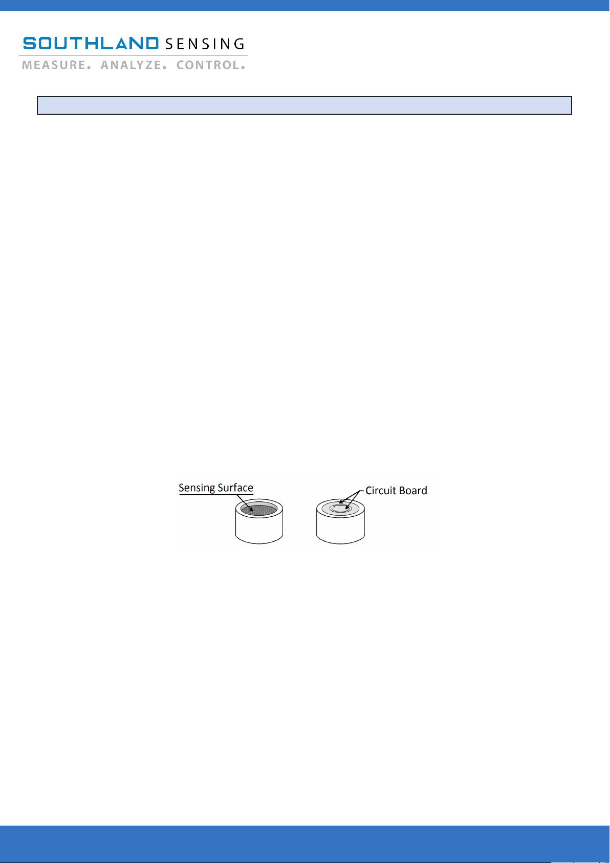
The oxygen sensor used in the OMD-525X is based on the
galvanic electrochemical fuel cell principal. All oxygen sensors
are manufactured in house by Southland Sensing Ltd. under a
strict quality program.
Thestandardcellsareunaectedbyotherbackgroundgases
such as H2, He or Hydrocarbons. The acidic cells work well
when acid gases such as CO2 or Natural Gas are present.
The sensors are self-contained and minimal maintenance is
required - no need to clean electrodes or add electrolyte.
TheSSO2precisionoxygensensorsoerexcellentperfor-
mance, accuracy and stability while maximizing the expected
life.
TO2-1x PPM Oxygen Sensor: Trace Analysis, Standard
TO2-2x PPM Oxygen Sensor: Trace Analysis, Acidic
PO2-160 Percent Oxygen Sensor: Percent Analysis, Standard
PO2-24 Percent Oxygen Sensor: Percent Analysis, Acidic
PO2-1120 Purity Oxygen Sensor: Percent Analysis, Standard
TO2-19 Hybrid Oxygen Sensor: Percent or Trace Analysis
Oxygen sensors should be periodically calibrated. Factory
recommendation is every 2 - 3 months or as the application
dictates.Sensorsoerexcellentlinearitywithanaircalibration,
orcalibratetoacertiedspangastomaximizeaccuracy.
The model OMD-525X oxygen analyzer combines a
rugged in-line design with SSO2’s precision oxygen
sensors. The result is a highly reliable and cost
eectivecompactdesignwithaneasy-to-useuser
interface.
Theanalyzercanbeconguredforeither10-28
VDCor100-240VACpowertotavarietyofappli-
cations.Itcanalsobeconguredfortrace,(parts-
per-million) percent, or purity analysis using the
on-board menu and correct sensor.
The auto-range feature allows the user to read O2
throughout all relevant ranges on the local display in
large font.
The output can be range selected through the on-
board menu allowing easy interface with a PLC, DCS
or other control system.
Gas connections are made with compression tube
ttings(1/8”,1/4”or6mm).
Gas Connections:
81/8”CompressionTubeFittings
41/4”CompressionTubeFittings
6 6 mm Compression Tube Fittings
2-nonlatchingfullycongurableFormCrelay
contact alarms.
Use This Part Number When Ordering
Designed, Tested, and Assembled in California, USA
Rev 1.02 July 19th, 2022_DF

1.4.1 General Safety & Installation (VAC)
This section summarizes the precautions applicable to the OMD-525X Oxygen Analyzer. Additional pre-
cautionsspecictothisanalyzerarecontainedinthefollowingsectionsofthemanual.Tooperatethe
analyzer safely and to obtain the best performance, follow the basic guidelines outlines in this owner’s
manual.
CAUTION:
WARNING:
CAUTION:
This symbol is used throughout the owner’s manual to warn and alert the
user of the presence of electrostatic discharge.
This symbol is used throughout the owner’s manual to caution and alert
the user to recommended safety and / or operating guidelines.
This symbol is used throughout the owner’s manual to caution and alert
the user that this device is operated on AC Voltage (VAC)
READ INSTRUCTIONS: Before operating the oxygen analyzer, read the instructions.
RETAIN INSTRUCTIONS: The safety precautions and operating instructions found in the owner’s
manual should be retained for future reference.
FOLLOW INSTRUCTIONS: Observe all precautions and operating instructions. Failure to do so may
result in personal injury or damage to the transmitter.
OXYGEN ANALYZER LABEL:
Introduction
OMD-525X Oxygen Analyzer
Designed, Tested, and Assembled in California, USA
Model Number: OMD-525X
Serial Number: 0036785
Oxygen Analyzer
Voltage: 100 - 240 VAC
Max Current: 100mA
4045 E. Guasti Rd. #203 Ontario, CA 91761 USA
Ph: (949) 398-2879 Web: www.sso2.com
This section is for AC powered analyzers, if your analyzer is DC powered proceed to the next page.

1.4.2 General Safety & Installation (VDC)
This section summarizes the precautions applicable to the OMD-525X Oxygen Analyzer. Additional pre-
cautionsspecictothisanalyzerarecontainedinthefollowingsectionsofthemanual.Tooperatethe
analyzer safely and to obtain the best performance, follow the basic guidelines outlines in this owner’s
manual.
CAUTION:
WARNING:
CAUTION:
This symbol is used throughout the owner’s manual to warn and alert the
user of the presence of electrostatic discharge.
This symbol is used throughout the owner’s manual to caution and alert
the user to recommended safety and / or operating guidelines.
This symbol is used throughout the owner’s manual to caution and alert
the user that this device is operated on DC Voltage (VDC)
READ INSTRUCTIONS: Before operating the oxygen analyzer, read the instructions.
RETAIN INSTRUCTIONS: The safety precautions and operating instructions found in the owner’s
manual should be retained for future reference.
FOLLOW INSTRUCTIONS: Observe all precautions and operating instructions. Failure to do so may
result in personal injury or damage to the transmitter.
OXYGEN ANALYZER LABEL:
Introduction
OMD-525X Oxygen Analyzer
Designed, Tested, and Assembled in California, USA
Model Number: OMD-525X
Serial Number: 0036785
Oxygen Analyzer
Voltage: 10 - 28 VDC
Max Current: 100mA
4045 E. Guasti Rd. #203 Ontario, CA 91761 USA
Ph: (949) 398-2879 Web: www.sso2.com
This section is for DC powered analyzers, if your analyzer is AC powered see the previous page.

1.5 Location Installation Considerations
The Southland Sensing OMD-525X Oxygen Analyzer is designed to be wall mounted in a general
purpose area and uses a NEMA4X / IP66 Enclosure. When installed outdoors in cold areas an optional
heater is recommended as well. Consider also giving the analyzer a sun shield if it is going to be
mounted in the direct sunlight.
Reference your local electrical authority for the proper installation.
The analyzer is EMI / RFI protected, however it is good practice not to mount it too close to sources
of electrical interference such as large transformers, motor start contactors, relays, large pumps, etc.
Alsoavoidsubjectingtheanalyzertosignicantvibration.
Mount the unit at a suitable eye level to easily read the local display. Gas connections are located on
the top right side of the analyzer, ensure there is adequate room to hook up your gas lines.
1.6 Safety Considerations
The oxygen analyzer is designed for installation into a general purpose area. Please follow your local
electrical code.
Designed, Tested, and Assembled in California, USA
Introduction
OMD-525X Oxygen Analyzer

2.1 Receiving Your New Oxygen Analyzer
As soon as you receive your new oxygen analyzer carefully unpack the unit and accessories and inspect
the interior and exterior of the analyzer for damage, and also verify the oxygen sensor is present.
CAUTION: Do not open the oxygen sensor packaging at this time. It is packed in a ni-
trogen purged bag and will be damaged if left exposed to ambient air for a prolonged
period of time. It is recommended that you read through the instruction manual
installation and operation sections before attempting to open the bag the oxygen
sensor is packed in. For questions, please contact the factory.
If damage to any portion of the new analyzer is present, stop and report damage to the shipping com-
pany as well as the factory.
The analyzer is shipped with all materials needed to install and prepare the system for operation. In
some instances, added sample system components are necessary to condition the gas sample before en-
teringthesensorhousing.SouthlandSensingoersfreeapplicationconsultationandweencourageyou
to take advantage of our engineers and their expertise.
It is also important to be mindful of EMI / RFI noise interference. Protection from EMI / RFI noise is im-
portant for accurate readings.
Installation
OMD-525X Oxygen Analyzer
Designed, Tested, and Assembled in California, USA

2.2 Mounting the Oxygen Analyzer
The OMD-525X is designed for general purpose installations. If mounting in extreme temperature con-
sider a secondary heated enclosure.
Refer to Part 3: Operation section of this instruction manual for more information on how to operate the
controls of this oxygen analyzer.
RefertoPart4:Maintenancesectionforanoverviewonhowtocalibratethedeviceusingacertied
span gas or ambient air.
A precision electrochemical oxygen sensor is included as a separate item and must be installed prior to
instrument use.
CAUTION: Do not open the nitrogen lled oxygen sensor bag until you have thoroughly read
the instruction manual and have made all gas and electrical connections. Please refer to
section 2.5 to reference installing the oxygen sensor into the sensor housing as well as sec-
tion 4.1 and 4.2 on SPAN Calibration.
When installing the analyzer, it is important to make sure the unit is wall mounted standing upright. This
ensures the sensor is always facing down (sensing surface down, circuit board up) to allow any air bub-
bles to not interfere with the sensing membrane.
Designed, Tested, and Assembled in California, USA
Installation
OMD-525X Oxygen Analyzer
Oxygen Sensor Front and Rear View
The sensor housing has 4 wires and should arrive wired to the circuit board, into the green termi-
nal block as follows:
Sensor (+) red wire = Sensor (+) Pin
Sensor (-) black wire = Sensor (-) Pin
Temp Comp white wire = Sensor TH Pin
Temp Comp green wire = Sensor TH Pin

2.2 (Cont) Mounting the Oxygen Analyzer
Designed, Tested, and Assembled in California, USA
Installation
OMD-525X Oxygen Analyzer
OMD-525X Mounting Dimensions.
Sizes are in mm and inches

2.3.1 Electrical Connections (VAC)
Incoming power/signal output
connections are made to the green
terminal block located on the
Back of the unit.
Donotsupplyvoltagemorethanspeciedin
this manual and noted on the analyzer
label inside of the unit.
Shielded cable is recommended when
connecting power and signal output.
Voltage: 100 - 240 VAC
Max Current: 100 mA
Avoid electrostatic discharge
** Note: This device is designed to be integrated
with a PLC or DCS system. The power input should
be 100 - 240 VAC. The electronics self generate a
4 - 20mA analog output.
DO NOT hook up power to either the ANALOG
OUTPUT or RANGE ID as the circuit will be dam-
aged.
Follow your local electrical
authority for proper procedure.
It is also recommended to
make sure you have the proper seals for your
condulet to meet your required installation
consideration. Check with your local electrical
authority.
Designed, Tested, and Assembled in California, USA
Installation
OMD-525X Oxygen Analyzer
This section is for AC powered analyzers, if your analyzer is DC powered proceed to the next page.
Modbus Grnd
4-20 mA Negative
0-1 VDC Negative
4-20 mA Positive
0-1 VDC Positive
Modbus A
Modbus B
Relay 1 NC
Relay 1 NO
Relay 1 Common
Relay 2 NC
Relay 2 NO
Relay 2 Common
Power (-)
Power (+)
Ground

2.3.2 Electrical Connections (VDC)
Incoming power/signal output
connections are made to the green
terminal block located on the
Back of the unit.
Donotsupplyvoltagemorethanspeciedin
this manual and noted on the analyzer
label inside of the unit.
Shielded cable is recommended when
connecting power and signal output.
Voltage: 10 - 28 VDC
Max Current: 100 mA
Avoid electrostatic discharge
** Note: This device is designed to be integrated
with a PLC or DCS system. The power input should
be 10 - 28 VDC. The electronics self generate a 4 -
20mA analog output.
DO NOT hook up power to either the ANALOG
OUTPUT or RANGE ID as the circuit will be dam-
aged.
Follow your local electrical
authority for proper procedure.
It is also recommended to
make sure you have the proper seals for your
condulet to meet your required installation
consideration. Check with your local electrical
authority.
Designed, Tested, and Assembled in California, USA
Installation
OMD-525X Oxygen Analyzer
This section is for DC powered analyzers, if your analyzer is AC powered go to the previous page.
Modbus Grnd
4-20 mA Negative
0-1 VDC Negative
4-20 mA Positive
0-1 VDC Positive
Modbus A
Modbus B
Relay 1 NC
Relay 1 NO
Relay 1 Common
Relay 2 NC
Relay 2 NO
Relay 2 Common
Power (-)
Power (+)
Ground

2.4 Gas Connections
The OMD-525X can accept either a TO2-1x or TO2-2x (for CO2 applications, i.e. natural gas) oxygen sen-
sor for trace oxygen analysis. For percent measurement, the OMD-525X can accept either a PO2-160 or
PO2-24 (for CO2 applications) oxygen sensor. For high purity percentage levels of oxygen the PO2-1120
sensor should be used. For a hybrid application where the user is monitoring oxygen from 50 ppm up to
21.0% with regular exposure to ambient air, consider the TO2-19 Hybrid Oxygen Sensor. For help selecting
a sensor, contact your local sales rep or the factory.
Prior to installing the sensor, it is important to make sure that the analyzer gas lines are hooked up and
theunitisreadytopurgewithazeroorprocessgas.Connectthezerogaslineandsetyourowbetween
0.50 - 5.0 SCFH.
To Install the Sensor:
- Remove the four screws and open the front of the analyzer.
- Remove the cell holder cap by unscrewing the stainless steel collar.
- Lift up on the top of the sensor housing and set it to the side.
- Inspect O-ring for cracking, replace if necessary. Always lube your O-rings!
- Remove the sensor from its box. With scissors, open nitrogen purged packaging
and remove the sensor.
- Visually inspect sensor for damage, if damaged notify the factory immediately.
- Remove the shorting tab across the back of the sensor circuit board (red
tape).
- Place the sensor inside the housing with the metal mesh screen facing down and
the circuit board contacts facing up.
- Return upper portion of the sensor housing to the stainless steel bottom. Tighten
collar. Hand tight is acceptable to create an airtight seal.
- Immediately start purge of zero gas.
- If the analyzer has not been calibrated, refer to section 4.1 for more information.
** Sensor should not be exposed to ambient air for more than 2 minutes. Extended periods of
exposure can damage the low end sensitivity and response time.
CAUTION: Prior to installing the oxygen sensor read section 4.1 on per-
forming a span calibration.
Oxygen Sensor Front and Rear View
2.5 Installing the Oxygen Sensor
GasConnectionsaremadeviacompressiontubettingsdirectlyontheanalyzer,inlet/outletcanowin
eitherdirection.Varioustubettingssizesareavailable,checkwiththebuildsheetforspecicgascon-
nection sizes.
Designed, Tested, and Assembled in California, USA
Installation
OMD-525X Oxygen Analyzer

3.1 Understanding the Controls and their Operation
The OMD-525X Oxygen Analyzer is a feature packed unit with an easy-to-use menu interface. The
key attributes within the menu are the ability to select a measurement range manually or using the
auto-range mode, to calibrate the unit with a known gas, also referred to as a SPAN Calibration or
SPAN CAL, and to perform a zero calibration (if necessary, most applications it is not required).
All features are programmable / selectable through the MENU button. The UP / DOWN buttons will
allow you to select your set points and the ENTER button saves the data. If you want to cancel your
selection, or return to the previous screen the escape key ESC will allow you to do this. Once the unit
starts up, the following home screen will appear:
Operating O2 Levels
Current Oxygen Reading
Identier,Manual
or Auto Range
Operation
OMD-525X Oxygen Analyzer
Designed, Tested, and Assembled in California, USA
ALARM 1
LOW
20.9
PERCENT
Alarm 2 Setting
Alarm 1 Setting
Alarm 1 O2 Level Alarm 2 Range
ALARM 2
HIGH
209
PPM
12 : 00 : 00 01 Jan 2022
PERCENT
RANGE LOCKED
0 TO 25 %
20.90
Operating Range

3.2 Setting the Date and Time
The OMD-525X oxygen analyzer is equipped with an onboard time and date stamp on the main screen.
This function is important to keep accurate if you are goin gto be taking advantage of the integral USB
data logging.
ThetimeissettoPacicStandardTime,ifyouarelocatedoutsideofthattimezoneitissuggested
that you adjust the time to your local standard time. The date may also need to be adjusted.
Designed, Tested, and Assembled in California, USA
Operation
OMD-525X Oxygen Analyzer
MAIN MENU
AUTO RANGE
MANUAL RANGE
SPAN CAL
ZERO CAL
SET TIME
SET DATE
CONFIG ALARM 1
CONFIG ALARM 2
LOGGING INTERVAL
SYSTEM
SET TIME
12 : 00 : 00
UP TO INCREASE
DOWN TO DECREASE
ENTER TO SAVE
SET DATE
01 JAN 2022
UP TO INCREASE
DOWN TO DECREASE
ENTER TO SAVE
To set the time or date, start by pressing the MENU key to open up the
onboard menu.
To set the time, select the SET TIME function. From here it will allow
you to adjust the hours, minutes, and seconds using the UP and DOWN
keys. The number being changed will be highlighted, press ENTER to
proceed to the next one.
To set the date, select the SET DATE function. This will allow you to
adjust the day, month, and year using the UP and DOWN keys, the pro-
cess being nearly identical to setting the time.

3.3 Measurement Range Overview
TheOMD-525Xoxygenanalyzerallowstheusertoeldselect5availableranges-customrangescan
be programmed in the built-in menu, see Section 3.7. These ranges can be selected in manual mode,
meaning they are locked into that range by the user, or they can be set to auto-range so the analyzer
will adjust to give you the best full scale resolution.
When using the Manual-Range mode the Manual Range locks the 4 - 20mA output to a single range,
and the display will continue to operate in auto-range mode giving the user the full spectrum of
analysis ranges. Other manufactures lock the display as well - the problem is if you over-range and
the display is locked you have no idea what your oxygen value is. The OMD-525X solves this issue
with a display that auto-ranges and the ability to manually lock the analog outputs.
To select Auto-Range or Manual-Range Mode, from the HOME screen, press the MENU key and the
display will indicate:
Using the UP / DOWN keys to change which option is highlighted
will allow the user to select AUTO-RANGE, which will all the unit to
cyclethroughallveranges,orMANUALRANGEwhichwillallow
theusertoselectaspecicrange.
Decide which option will work best for your application.
Highlight the selection and press the ENTER key. If you
have selected the AUTO RANGE option, it will blink for a
second indicating this was selected. If you selected the
MANUAL RANGE option, the following screen will be brought up:
**Note:AnalyzerscanbeconguredforTrace,Percentand
PurityAnalysissoyourrangesmightbedierent.
Trace: 0 - 10ppm, 0 - 100ppm, 0 - 1000ppm, 0 - 10000ppm, 0 - 25%
Percent: 0 - 1%, 0 - 5%, 0 - 10%, 0 - 25%, 0 - 100%
If a custom range has been set, it will appear below the 0 - 10 ppm range.
Use the UP / DOWN keys to highlight the range to be selected and press the ENTER key. The se-
lected range will blink for a second indicating the range has been selected.
Press the ESC key to move back to the previous screen.
Designed, Tested, and Assembled in California, USA
Operation
OMD-525X Oxygen Analyzer
MAIN MENU
AUTO RANGE
MANUAL RANGE
SPAN CAL
ZERO CAL
SET TIME
SET DATE
CONFIG ALARM 1
CONFIG ALARM 2
LOGGING INTERVAL
SYSTEM
MANUAL RANGE
0 - 25%
0 - 10000 PPM
0 - 1000 PPM
0 - 100 PPM
0 - 10 PPM

3.4 Analog Output
** Caution: Integral 4 - 20mA converters are internally powered and do not re-
quire external power. DO NOT supply any voltage across these terminals as the
4 - 20mA output will be damaged. It is also important to assure proper ground-
ing of the external recording device such as a PLC, DCS prior to connecting the 4
- 20mA.
The OMD-525X is equipped with a 4 - 20mA analog output. When physically connecting the analog
output, refer to the circuit board pinout in section 2.3
To verify the signal output of the 4 - 20mA circuit is working properly, connect an ammeter across the
(+) and (-) pins. With no oxygen sensor connected, it should read approximately 4 mA. If a sensor is
installed you can verify the signal matches with the following formula:
Signal Output (mA) = [(Reading / Full Scale Range) x 16] + 4
For example, if we are reading 500ppm on the 1000 ppm range:
Signal Output (mA) = [(500/1000) x 16] + 4
Signal Output (mA) = 12mA
The OMD-525X has a menu feature that allows the analog output to be adjusted to compensate for
any internal resistance in the connection. To adjust the 4 - 20mA enter the MENU and select SYSTEM,
then select OUTPUT CAL. Push the UP or DOWN buttons to adjust the 4mA zero setting, continue to
push UP and DOWN as needed. Once complete, you will be promted to adjust the upper 20mA out-
put in the same fashion with the UP and DOWN bottons.
Designed, Tested, and Assembled in California, USA
Operation
OMD-525X Oxygen Analyzer

The OMD-525X Oxygen Analyzer is equiped with 2 advanced relay contact alarms. These alarms can
beconguredasnormallyopenornormallyclosed,haveadelaymodebuilt-in,andcanbeenabled
or disabled when necessary.
The alarms are rated at 5A @ 230VAC. If you are connecting to solenoid valves or a pump whose
currentcanuctuategreatly,itisadviseabletouseaslaverelaytoensurenodamageoccurstothe
electronics.
The procedure for setting Alarm 1 and Alarm 2 is identical. To begin,
highlightthealarmcongurationyouwanttoadjustusing
the UP / DOWN keys in the analyzer MENU and press ENTER.
To adjust the value setpoint of ALARM 1 simply highlight ALARM 1
and press ENTER. Select the ADJUST ALARM option, where you
will be able to adjust the levels using the UP / DOWN buttons. To set
a PPM level alarm simply hold the DOWN button until you get below
1%. To set the alarm press ENTER.
The alarm function allows the user to set the alarm to trigger the relay
contacts as a HIGH alarm or a LOW alarm. Simply
open the ALARM 1 menu and UP or DOWN to meet your
requirements.
The alarm has a built in DELAY TIME. This is ideal to use when you
are working on your process and do not want to have the alarm relay
contacts trip. You will set this in a similar fashion to setting the alarm.
The DELAY TIME is in minutes, so adjust the value accordingly.
The alarm can also be enabled / disabled should it be hooked up but
not required. Highlight ALARM ON/OFF using the UP / Down keys to
and press the ENTER key.
The alarms can function as normally open or normally closed. This
selection will be choosen when hooking up the rear wiring, it is not
completed through the software. See the wiring diagram in section 2.4
for more information.
If you any questions about the ALARM functions should arise, please
contact the factory for assistance or technical questions.
3.5 Advanced Integral Alarms
Operation
OMD-525X Oxygen Analyzer
Designed, Tested, and Assembled in California, USA
ALARM 1 MENU
ALARM ON/OFF
ALARM HI/LOW
ADJUST ALARM
DELAY TIME
ALARM 1
LOW
UP SETS ALARM HIGH
DOWN SETS ALARM LOW
ENTER TO SAVE
ESC TO EXIT
19.5%
UP TO INCREASE
DOWN TO DECREASE
ENTER TO CAL
ESC TO EXIT
SET INTERVAL
IN MINUTES
0
UP TO INCREASE
DOWN TO DECREASE
ENTER TO SET
ESC TO EXIT
Alarm adjustment screen
Alarm delay screen
MAIN MENU
AUTO RANGE
MANUAL RANGE
SPAN CAL
ZERO CAL
SET TIME
SET DATE
CONFIG ALARM 1
CONFIG ALARM 2
LOGGING INTERVAL
SYSTEM

** Caution: RANGE ID converters are internally powered and do not require external power.
DO NOT supply any voltage across these terminals as the output will be damaged. It is also
important to assure proper grounding of the external recording device.
Refer to section 2.3 for electrical wiring diagram.
When connecting the RANGE ID, connect to the (+) positive and (-) negative sides of the RANGE
output on the rear of the analyzer. To verify the signal output of the RANGE ID is working properly,
connect a voltmeter across the terminals to verify. You can change the range manually in MANUAL
RANGE mode to verify:
PPMCong. PercentCong. Output
Range 1 0 - 10 ppm 0 - 1% 1 VDC
Range 2 0 - 100 ppm 0 - 5% 2 VDC
Range 3 0 - 1000 ppm 0 - 10% 3 VDC
Range 4 0 - 10000 ppm 0 - 25% 4 VDC
Range 5 0 - 25% 0 - 100% 5 VDC
3.6 Range ID
Operation
OMD-525X Oxygen Analyzer
Designed, Tested, and Assembled in California, USA
Table of contents
Other Southland Analytical Instrument manuals