General Specifications
43
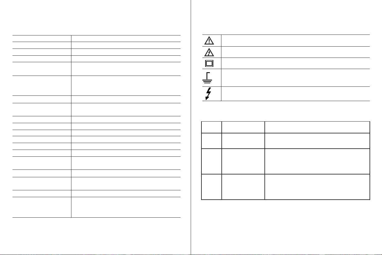
International SafetySymbols
Potential danger. Indicates the user must refer to the
manual for important safety information.
Indicates hazardous voltages may be present
Equipment is protected by double or reinforced insulation
Indicates the terminal(s) so marked must not be connected to a circuit where
the voltage with respect to earth ground exceeds the maximum safety rating
of the meter .
Indicates the terminal(s) so marked may be
subjectedto hazardous voltages.
MAX
600V
Insulation
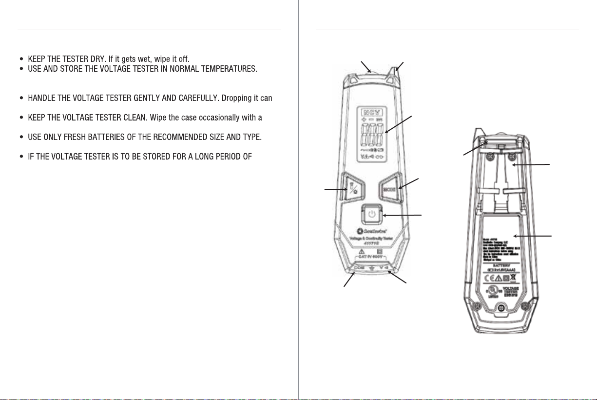
Display
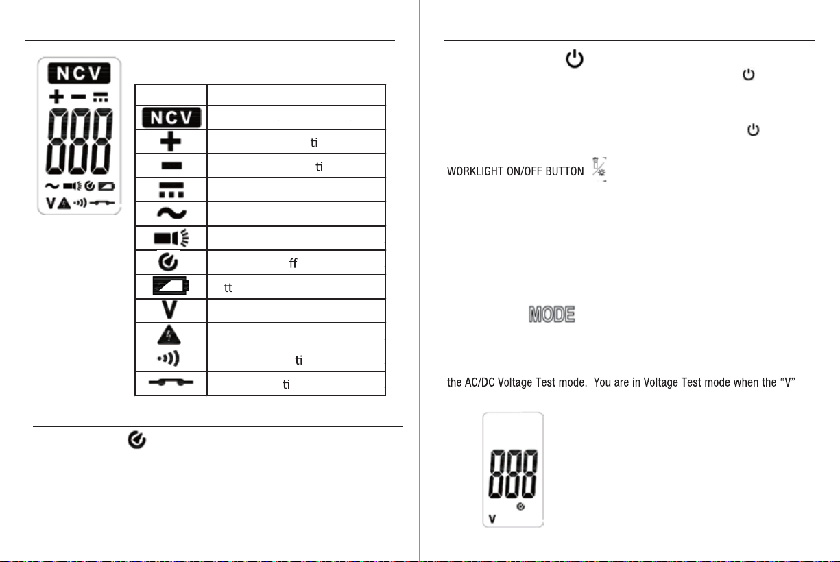
DC Polarity
OverRange Indication
Continuity
Low Battery Indication
Measurement Rate
AutoPower Off
Input Impedance
AC Response
AC Bandwidth
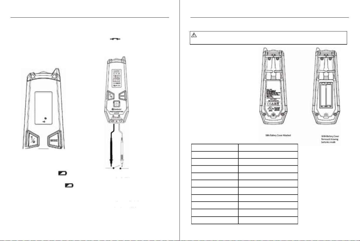
Battery:
Operating Temperature
StorageTemperature
Relative Humidity
Operating Altitude
Weight
Dimensions:
Safety:
Class 2, Double insulation.
LCD
Automatic. “+“ / “-“ is displayedfor polarity
“OL” is displayed
Audible indication if the resistance is
approximately 10KΩor less
Low battery symbol will appear inLCD
display when the battery voltage is too low
for normaloperation
3times per second, nominal
Meter automatically shuts downafter approx.
15 minutesof inactivity
AC/DC voltage: ≥10MΩ
Average responding
50/60Hz
Two AAA batteries
32°F to 122°F (0°C to 50°C)
14°F to 122°F (-10°C to 50°C)
Maximum, non-condensing: 95% up to 82°F (28°C),
75% to 104°F (40°C), 45% to 122°F (50°C)
0-2000 meters
5ounces (142 grams) includes 2-AAA batteries,
not including test leads
6.3” x 2.2” x 1.4” (160 x 55 x 35mm)
UL: 61010 - 1:2012, 61010-2-030: 2012,
61010-2-033: 2014
EMC:EN61326-1:2013, EN61326-2-2:2013
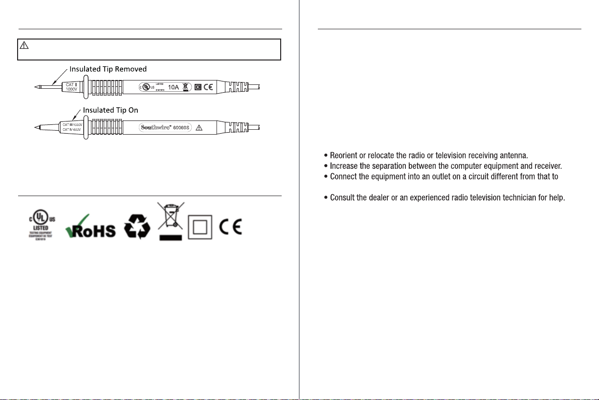
The measurement category (CAT) rating and voltage rating is determined by a combination of the meter,
the test probes and any accessories connectedto the meter and test probes. The combination rating is the
LOWEST rating of any individual component
Brief Description Typical Applications
Category
Rating
Single phase receptacles
and connected loads
Three phase circuits and
single phase lighting
circuits in commercial
buildings
- Household appliances, power tools
- Outlets more than 30ft (10m) from a CAT III source
- Outlets more than 60ft (20m) from a CAT IV source
- Equipment in fixed installations such as 3-phase
motors, switchgear and distribution panels
- Lighting circuits in commercial buildings
- Feeder lines in industrial plants
- Any device or branch circuit that is close to a CAT III source
CAT II
CAT III
Connection point to utility
power and outdoor
conductors
- Primary distribution panels
- Overhead or underground lines to detached buildings
- Incoming service entrance from utility
- Outdoor pumps
CAT IV
Safety Category Ratings