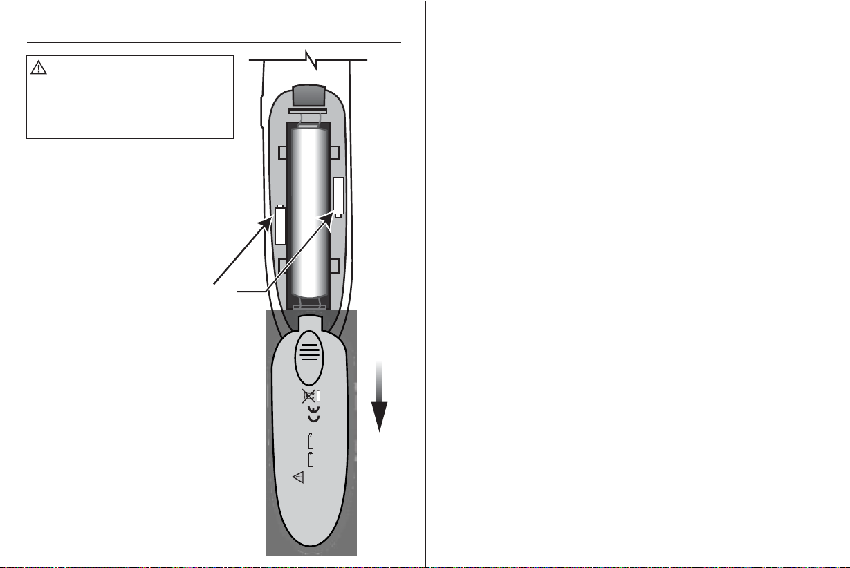
Southwire T200K User manual

Operating Instructions
T200K Multipurpose Wire Tracing Kit
T200K
T200K
Tone
Transmisor y
Receptor
Contents Made in China
Product distributed by Southwire Company, LLC
One Southwire Drive, Carrollton, GA 30119
©2014 Southwire Company, LLC. All rights reserved.
southwiretools.com
1-855-SW-T00LS
Toll Free Technical Help
Línea de Ayuda Técnica Gratuita
Scan for a how-to video,
warranty informaon and
to access our mobile site.
Escanea para video
04/14 Rev. 0
T200K manual
Instrucciones de Operación
Kit Multiusos para Trazar Alambres T200K

Introduction
The Southwire T200K Wire Tracer Kit can be used to trace
Phone, Data, Coax and General Purpose wiring.
The kit includes a transmitter, receiver, and adapters for
connection to multiple types of cables. All the components
are conveniently stored in a carrying case with belt clip.
With proper use, this tester will provide many years of
reliable service.
3. HANDLE THE TESTER WITH CARE.
Dropping it can damage the electronic parts or the case.
4. KEEP THE TESTER CLEAN. Wipe the case occasionally with
a damp cloth. DO NOT use chemicals, cleaning solvents, or
detergents.
5. USE ONLY FRESH BATTERIES OF THE RECOMMENDED
SIZE AND TYPE. Remove old or weak batteries so they do
not leak and damage the unit.
6. IF THE TESTER IS TO BE STORED FOR A LONG PERIOD
OF TIME, the batteries should be removed to prevent
damage to the unit.
Maintenance cont.
1 2
Instructions in this manual before using this tester.
No serviceable parts are inside.
electrical storms.
WARNINGS
Tone Signal Frequency
Tone Output Power
Tone Auto-Off
Battery (Transmitter and Receiver)
Operating Temperature
Storage Temperature
Case dimensions
Tone dimensions
Probe dimensions
Weight
2.72 kHz nominal
+24 dbm into 600 ohms
30min
Two “AAA” 1.5V Batteries in each unit
4°F to 140°F (-20° to 60°C)
-40°F to 158°F (-40° to 70°C)
7.06 in. x 3.19 in. x 2.04 in.
(17.9 cm x 8.1 cm x 5.2 cm)
5.17 in. x 0.94 in. x 1.32 in.
(13.2 cm x 2.4 cm x 3.4 cm)
6.18 in. x 0.94 in. x 1.32 in.
(15.7 cm x 2.4 cm x 3.4 cm)
0.7lb (322g)
This tester is designed to provide years of dependable service,
if the following care instructions are performed:
1. KEEP THE TESTER DRY. If it gets wet, wipe it off.
2. USE AND STORE THE TESTER IN NORMAL
TEMPERATURES. Temperature extremes can shorten the life
of the electronic parts and distort or melt plastic parts.
Maintenance

Tester Description Operation
3 4
WARNING: Electric shock hazard. Do not use tester on live circuits.
Never trace energized wiring.
1.
3.
Transmitter (Toner)
1. Power button
2. Transmitter-on LED
3. Transmitter output port
Receiver (Probe)
1. Sensor tip
2. Detector LED
3. Sensitivity control
4. TEST button
5. LED flashlight
Adapter Cables
1. Coax adapter with F connector
2. Data adapter with RJ45 connector
3. Phone adapter with RJ11 connector
4. Automotive fuse adapter
5. Alligator clip adapter
1. Open the storage case by pressing on the red latch.
Remove the appropriate adapter and connect it to the transmitter
output port. Connect the other end of the adapter to the cable
being traced.
2. Momentarily press the power button on the transmitter (toner).
An LED will flash to indicate the transmitter is operating.
The transmitter will send a pulsating tone down the cable
being traced.
3. Press and hold the TEST button to activate the receiver (probe).
An LED flashlight will illuminate the work area.
4. The tone will become louder as the sensor tip moves closer to the
cable with the tone on it.
A red LED will illuminate as the signal gets stronger.
Adjusting the sensitivity control can help pinpoint
the cable when multiple cables are in close proximity.
T200K
Tone
2.
1. 2. 3. 4.
5.
Open
Storage Case
RED Latch
RJ11
Clips
1.
4.
2.
3.
5.

5 6
Use the Phone Adapter to connect the Transmitter to a phone jack.
The signal will be sent through pins 3 and 4 (line 1) when connected
to a 6 position phone jack.
Use the Data Adapter to connect the Transmitter to a wall port or
patch panel. The tone will be sent through pins 4 and 5.
The tone will be loudest when the sensor tip is touching the
blue pair if the cable is wired to T568A or T568B standards.
To verify identification, separate the wires on the suspected pair
a few inches.
The tone should be significantly louder when to sensor tip is touching
either wire on the separated pair.
NOTE:
In order to avoid interference, disconnect the cable being tested
from the outside phone line.
Tracing Phone Cables
NOTE:
Use caution when tracing installed cable. The tone generator may
cause interference with other signals on adjacent conductors.
Tracing Data Cable
Receiver
Receiver
Phone
Cable
Phone Jack
Interior
Wires
Cable
Detail
Closeup
Phone Jack
Phone Adapter
Transmitter
Data Adapter
Wall Port
Transmitter

78
WARNING: Electric shock hazard. Do not connect tester to live circuits.
Never trace energized wiring.
Use the Coax Adapter to connect the Transmitter to a wall port or
patch panel.
The tone will be sent though the center conductor and shield on
the coax cable.
NOTE:
In order to avoid interference, disconnect the cable from the outside
cable service.
NOTE:
Certain types of splitters used in Cable TV systems will prevent tone
from passing through the splitter.
Tracing Coax Cables
Connect the Alligator Clip Adapter to the Transmitter.
Connect the Red Alligator Clip to one of the wires on the cable
being traced.
Connecting the Black Test Lead to earth ground will increase
the distance the tone can be detected.
When getting to the end of the cable, remove the ground connection
in order to pinpoint the cable location.
Tracing General Wiring
Coax Adapter
Transmitter
Wall Port
Cable
Receiver
Black
Red
Alligator Clip
Adapter
Cable
Transmitter
Receiver
(Shown searching for cable)

910
1. Slide off the battery cover.
2. Replace batteries with
two “AAA” 1.5V batteries.
3. Be sure to observe polarity
as shown on drawing.
4. Slide the battery cover back
onto the tester.
Battery Replacement (Transmitter and Receiver)
WARNING:
To avoid electric shock,
disconnect the tester from all circuits before
removing the battery cover. DO NOT operate
the tester until the battery cover has been
properly secured.
+
1.5V AAA
Top
Bottom
2 x 1.5V “AAA”
Observe Polarity As Shown.
Insert Batteries:
One on top of the other.
and Receiver
Transmitter
Remove
Cover
LIMITED WARRANTY AND LIMITATION OF LIABILITY ON SOUTHWIRE METERS & TESTERS
Southwire Company, LLC warrants this product to be free from defects in material and
workmanship for two years from the date of purchase. This warranty does not cover fuses,
disposable batteries, or damage arising from an accident, neglect, misapplication,
contamination, modification, improper maintenance or repair, operation outside of specifications,
or abnormal handling of the product. Southwire’s sole liability, and the purchaser’s exclusive
remedy, for any breach of this warranty is expressly limited to Southwire’s repair or replacement
of the product. Whether Southwire repairs or replaces the product will be a determination that
Southwire makes at its sole discretion. SOUTHWIRE MAKES NO WARRANTY THAT THE
PRODUCT WILL BE MERCHANTABLE OR FIT FOR ANY PARTICULAR PURPOSE.
SOUTHWIRE MAKES NO OTHER WARRANTY, EXPRESSED OR IMPLIED, OTHER THAN THE
WARRANTY SPECIFICALLY SET FORTH HEREIN. SOUTHWIRE WILL NOT BE LIABLE FOR
ANY INCIDENTAL, CONSEQUENTIAL, INDIRECT, SPECIAL, OR PUNITIVE DAMAGES FOR
ANY BREACH OF THIS WARRANTY.
This warranty is void if this product is used for rental purposes. No product reseller is authorized
to extend any other warranty on Southwire’s behalf relating to this product, and no such reseller
warranty will be binding on Southwire. If you have a warranty claim, or if the product needs to
be serviced during or after the warranty period set forth above, please contact the Customer
Service Department at 855-SWTOOLS (855-798-6657). The sender is responsible for all
shipping, freight, insurance, and packaging costs associated with sending a product to
Southwire. Southwire will not be responsible for lost or damaged products returned pursuant
to this warranty. All products returned to Southwire under this warranty should be mailed to:
Southwire Company, LLC
Attention: Tool Warranty Return
5810 Trade Center Court
Villa Rica, GA 30180-6701
REGISTER YOUR PRODUCT
Register your product purchase at www.southwiretools.com or by scanning the QR code on this
manual. At Southwire, we are dedicated to providing you with the best customer experience. By
following a few quick steps to register, you can experience quicker service, more efficient support,
and receive information on our future products. Simply provide your model number, serial number,
and just a few pieces of information about yourself – it is that quick and easy.
1.5V AAA
+

Introducción
El Kit para Trazar Alambres Southwire T200K se puede usar para
trazar alambres de teléfonos, datos, cables coaxiales y cableado
de uso general. El kit incluye un transmisor, receptor y adaptadores
para hacer la conexión a diferentes tipos de cables. Todos los
componentes están almacenados convenientemente en un
estuche que se puede llevar en el cinturón. Bajo el uso apropiado,
este aparato puede dar muchos años de servicio confiable.
3. MANEJE EL PROBADOR CON CUIDADO.
Dejarlo caer puede dañar las piezas electrónicas
o su carcasa.
4. MANTENGA EL PROBADOR LIMPIO.
Límpielo ocasionalmente con un paño húmedo.
NO use químicos, solventes de limpieza ni detergentes.
5. UTILICE SOLO PILAS NUEVAS Y DEL TAMAÑO Y TIPO
ESPECIFICADO. Retire las pilas viejas para que no dañen
el aparato.
6. SI EL PROBADOR SERÁ ALMACENADO POR UN PERIODO
DE TIEMPO LARGO, la pila se debe retirar para que no dañe
el aparato.
Mantenimiento cont.
1 2
• Lea, entienda y siga todas las Reglas de Seguridad e
Instrucciones de Operación en este manual antes de usar
este probador.
• Peligro de electrocución. No conecte el probador a un circuito
activo. Nunca utilice el probador para trazar cableado energizado.
• No utilice el probador ni las sondas de pruebas si parecen estar
dañados.
• No modifique ni trate de reparar el probador.
No contiene piezas que se puedan reparar.
• No utilice el probador en un ambiente mojado o húmedo
ni durante tormentas eléctricas.
• No utilice el probador cerca de gases, polvo o vapores
explosivos.
• Para uso en interiores únicamente.
ADVERTENCIA
Especificaciones Generales
Frecuencia de Señal de Tono
Potencia de Salida del Tono
Auto Apagado del Tono
Pila (Transmisor y Receptor)
Temperatura de Operación
Temperatura de Almacenamiento
Dimensiones del Estuche
Dimensiones del Tono
Dimensiones del Sensor
Peso
2.72 kHz nominal
+24 dbm en 600 ohmios
30min
Dos pilas “AAA” 1.5V en cada unidad
4°F hasta 140°F (-20° hasta 60°C)
-40°F hasta 158°F (-40° hasta 70°C)
7.06 pulg. x 3.19 pulg. x 2.04 pulg.
(17.9 cm x 8.1 cm x 5.2 cm)
5.17 pulg. x 0.94 pulg. x 1.32 pulg.
(13.2 cm x 2.4 cm x 3.4 cm)
6.18 pulg. x 0.94 pulg. x 1.32 pulg.
(15.7 cm x 2.4 cm x 3.4 cm)
0.7lb (322g)
Este probador está diseñado para dar años de servicio
confiable, si se siguen las siguientes instrucciones de cuidado:
1. MANTENGA EL PROBADOR SECO. Si se moja, séquelo.
2. UTILICE Y ALMACENE EL PROBADOR BAJO
TEMPERATURAS NORMALES. Las temperaturas extremas
pueden acortar la vida de las piezas electrónicas y
distorsionar o derretir las piezas plásticas.
Mantenimiento

Descripción del Probador Operación
3 4
ADVERTENCIA: Peligro de electrocución. No use el probador en
circuitos activos. Nunca use el probador para trazar cables energizados.
1.
3.
Transmisor (Tono)
1. Botón de potencia
2. LED del transmisor
encendido
3. Puerto de salida
del transmisor
Receptor (Sensor)
1. Punta del sensor
2. LED detector
3. Control de sensibilidad
4. Botón de TEST
5. Linterna LED
Cables Adaptadores
1. Adaptador coaxial con conector tipo F
2. Adaptador de datos con conector RJ45
3. Adaptador para teléfono con conector RJ11
4. Adaptador de fusibles para autos
5. Adaptador de pinza de cocodrilo
1. Para abrir el estuche de almacenamiento presione el pestillo rojo.
Retire el adaptador apropiado y conéctelo al puerto de salida del
transmisor. Conecte el otro lado del adaptador al cable que será
trazado.
2. Presione por un momento el botón de potencia en el transmisor (tono).
Una luz LED destellará para indicar que el transmisor está funcionando.
El transmisor enviará un tono pulsado por el cable que se está trazando.
3. Presione y sujete el botón TEST para activar el receptor (sensor).
Una linterna LED iluminará el área de trabajo.
4. El tono se hará más alto según la punta del sensor se acerca más al
cable que tiene el tono. Una luz LED roja se iluminará según se hace
más fuerte la señal. Ajuste la sensibilidad para ayudar a localizar el
cable cuando tenga varios cables en su proximidad.
T200K
Tone
2.
1. 2. 3. 4.
5.
Abrir Estuche
de Almacenamiento
Pestillo ROJO
RJ11
Clips
1.
4.
2.
3.
5.

5 6
Utilice el Adaptador de Teléfono para conectar el Transmisor a la toma
de teléfono. La señal será enviada por los pines 3 y 4 (línea 1) cuando
esté conectado a una toma de 6 posiciones.
Utilice el Adaptador de Cables de Datos para conectar el Transmisor
al puerto en la pared o panel de interconexión. El tono será enviado
por los pines 4 y 5.
El tono será más alto cuando la punta del sensor esté tocando el par
azul si el cable está cableado según estándares T568A o T568B.
Para confirmar la identificación, separe los alambres en el par
sospechado por unas pulgadas.
El tono debe ser más alto cuando la punta del sensor esté tocando
uno de los alambres en el par separado.
NOTA:
Para evitar la interferencia, desconecte el cable bajo prueba de la línea
de teléfono exterior.
Trazar Cables de Teléfonos
NOTA:
Tenga cuidado al trazar cables instalados. El generador de tono puede
causar interferencia con otras señales en conductores adyacentes.
Trazar Cable de Datos
Receptor
Receptor
Cable
del Teléfono
Toma del
Teléfono
Interior
Alambres
Cable
Primer
del detalle
Toma del Teléfono
Adaptador
de Teléfono
Transmisor
Adaptador de
Cable de Datos
Puerto en la Pared
Transmisor

78
ADVERTENCIA: Peligro de electrocución. No conecte el probador a
circuitos activos.
Utilice el Adaptador de Cable Coaxial para conectar el Transmisor
al puerto en la pared o panel de interconexión.
El tono será enviado por el conductor central y aislamiento en el cable
coaxial.
NOTA:
Para evitar la interferencia, desconecte el cable del servicio de cable
exterior.
NOTA:
Ciertos tipos de separadores utilizados en sistemas de televisión por
cable no permiten que el tono pase por el separador.
Trazar Cables Coaxiales
Conecte el Adaptador de Pinza de Cocodrilo al Transmisor.
Conecte la Pinza de Cocodrilo Roja a uno de los alambres en el cable
que se está trazando.
Conecte el Cable de Prueba Negro a tierra para aumentar la distancia
a la que se puede detectar el tono.
Al acercarse al final del cable, retire la conexión a tierra para poder
determinar con precisión la ubicación del cable.
Trazar Cableado de Uso General
Adaptador de
Cable Coaxial
Transmisor
Puerto en la Pared
Cable
Receptor
Negro
Rojo
Alligator Clip
Adapter
Cable
Transmisor
Receptor
(Muestra la búsqueda del cable)

910
1. Retire la tapa de la pila.
2. Cambie las pilas por dos
pilas “AAA” 1.5V nuevas.
3. Asegúrese de mantener la
polaridad indicada.
4. Vuelva a colocar la tapa de la
pila en el probador.
Instalación de Pilas (Transmisor y Receptor)
ADVERTENCIA:
Para evitar
electrocución, desconecte los cables de
hacer prueba de cualquier fuente de voltaje
antes de retirar la tapa de las pilas.
NO utilice el probador hasta que no tenga
la puerta de las pilas bien asegurada.
+
1.5V AAA
Top
Bottom
2 x 1.5V “AAA”
Observe la Polaridad
Indicada.
Inserte las Pilas:
Una sobre la otra.
Transmisor
y Receptor
Quite la
cubierta
1.5V AAA
+
REGISTRE SU PRODUCTO
Registre su producto en www.southwiretools.com o al escanear el código QR que está en este
manual. En Southwire, estamos dedicados a proveer la mejor experiencia al cliente. Al seguir
unos pasos rápidos para registrar su producto, usted puede recibir servicio más rápido, ayuda más
efectiva, e información acerca de futuros productos.Simplemente proporcione el número de modelo
y serie de su producto, y alguna información personal – es así de fácil y rápido.
GARANTÍA LIMITADA Y LIMITACIÓN DE RESPONSABILIDAD EN MEDIDORES Y
PROBADORES DE SOUTHWIRE
Southwire Company garantiza este producto contra defectos en materiales y mano de obra por
dos años desde de la fecha de compra. Esta garantía no cubre fusibles, baterías desechables,
ni daños como resultado de un accidente, negligencia, mala aplicación, contaminación,
modificación, mantenimiento o reparación indebida, uso fuera de las especificaciones, o
manipulación anormal del producto. La única responsabilidad de Southwire, y el único remedio
del comprador, por cualquier incumplimiento de esta garantía está limitada expresamente a la
reparación o reemplazo del producto por parte de Southwire. La reparación o reemplazo del
producto se hará bajo la determinación de Southwire y a su discreción.
SOUTHWIRE NO GARANTIZA QUE ESTE PRODUCTO SERÁ COMERCIABLE O ADECUADO PARA ALGÚN PROPÓSITO EN
PARTICULAR. SOUTHWIRE NO HACE NINGUNA OTRA GARANTÍA, EXPRESA O IMPLÍCITA, SALVO QUE LA GARANTÍA
ESPECÍFICAMENTE MENCIONADA EN ESTE PÁRRAFO. SOUTHWIRE NO SERÁ RESPONSABLE DE DAÑOS
INCIDENTALES, CONSECUENCIALES, INDIRECTOS, ESPECIALES, O PUNITIVOS POR CUALQUIER INCUMPLIMIENTO
DE ESTA GARANTÍA. Esta garantía no será válida si el producto se utiliza para propósitos de alquiler.
Ningún vendedor de productos está autorizado para extender la garantía a nombre de Southwire
en relación a este producto, y la garantía de ningún vendedor será vinculante para Southwire. Si
necesita reclamar una garantía, o si el producto necesita servicio durante o después del periodo
de garantía mencionado en este documento, por favor contacte a Servicio al Cliente al
855-SWTOOLS (855-798-6657) o visite www.southwiretools.com para obtener una autorización
para devolver (RA) el producto, en la página web, haga clic en “Service Department” para pedir
un número de RA).
Usted debe obtener un número RA de Southwire antes que Southwire pueda procesar la
reclamación de garantía o pueda hacer cualquier servicio. La persona que haga la devolución
será responsable de los costos de envío y seguro asociados con enviar un producto a Southwire.
Southwire no se responsabiliza por productos dañados o perdidos durante la devolución
relacionada a esta garantía.
Todos los productos que se devuelvan a Southwire bajo esta garantía se deben enviar a:
Southwire Company, LLC
Attention: Tool Warranty Return
5810 Trade Center Court
Villa Rica, GA 30180-6701
Table of contents
Languages:
Other Southwire Test Equipment manuals