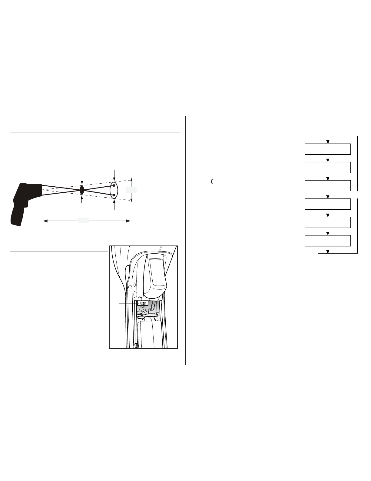
Southwire 31040S User manual

Operating Instructions
31040S Non-Contact Infrared Thermometer
31040S
®
Non-Contact
IR Thermometer
1500 F
DUAL LASER
-58.0 to 1500ºF
-50.0 to 815ºC
Instrucciones de Operación
Termómetro Infrarrojo Sin Contacto 31040S
Contents Made in China
Product distributed by Southwire Company, LLC
One Southwire Drive, Carrollton, GA 30119
©2014 Southwire Company, LLC. All rights reserved.
southwiretools.com
1-855-SW-T00LS
Toll Free Technical Help
Línea de Ayuda Técnica Gratuita
Scan for warranty informaon
and to access our mobile site.
Escanea para información de garana
y acceso a nuestro sio móvil.
12/14 Rev. 2
31040S manual

1
Introduction
The Southwire 31040S Infrared Thermometer measures surface temperature
without contact from -58° to 1500°F (-50° to 815°C). Dual lasers pinpoint the
target area and the 20:1 distance to spot size ratio allows measuring objects
at greater distance. Other features include fast response, MAX display, user
settable High/Low alarms, backlit display and adjustable emissivity. Proper
use and care of this meter will provide many years of reliable service.
• Use extreme caution when the laser beam
is turned on.
• Do not aim the laser beam at anyone’s eye or let
the laser beam strike the eye from a reflective surface.
• Do not use meter near explosive gases, vapors or dust.
• To avoid burns, understand that reflective objects can be
much hotter than the meter indicates.
• Replace the battery as soon as the low battery warning
appears on the LCD display.
• Do not use the meter if it appears damaged or is operating improperly.
• This product is intended for commercial and industrial use only.
It should not be used for medical evaluations.
SAFETY
• KEEP THE METER DRY. If it gets wet, wipe it off.
• USE AND STORE THE METER IN NORMAL TEMPERATURES. Temperature extremes
can shorten the life of the electronic parts and distort or melt plastic parts.
• HANDLE THE METER GENTLY AND CAREFULLY.
Dropping it can damage the electronic parts or the case.
• KEEP THE METER CLEAN. Wipe the case occasionally with a damp cloth.
DO NOT use chemicals, cleaning solvents, or detergents.
• USE ONLY FRESH BATTERIES OF THE RECOMMENDED SIZE AND TYPE.
Remove old or weak batteries so they do not leak and damage the unit.
• IF THE METER IS TO BE STORED FOR A LONG PERIOD OF TIME,
the batteries should be removed to prevent damage to the unit improperly.
This meter is designed to provide years of dependable service, if the following
care instructions are performed.
Maintenance
2
Meter Description
1. Data hold
2. Laser on symbol
3. Lock symbol
4. High alarm and low alarm symbols
5. °F/°C symbols
6. Low battery symbol
7. Emissivity symbol and value
8. MAX temperature
9. Symbol for MAX
10. Temperature reading
Display Description
1.
2.
6.
7.
1. IR sensor,
Laser pointer beams
2. LCD display
3. Up button
4. Down button
5. MODE button
6. Measurement trigger
7. Battery cover
8. Handle grip
Buttons
Up button (3.) (for laser on/off, and increasing values
in EMS, HAL, LAL settings)
Down button (4.) (for backlight on/off, and decreasing
values in EMS, HAL, LAL settings)
MODE button (5.) (for cycling through the MODE loop
2. 3. 4.
5.
6.
7.
1.
10.
9.
8.
3. 4.
5.
8.

3
1.
Operation
Selecting the temperature units (oF or oC).
Locate the two depressions on either side
of the meter near the trigger.
Pull down from this spot to open the
battery cover.
The selector slide switch (1.) is located
above the battery.
Gently shift the switch position to change
temperature units.
Distance&SpotSize
As the distance (D)from the object increases, the spot size (S) of the area
measured becomes larger. The meter’s D:Sratio is 20:1, so at 20 inches (508mm),
the diameter of the target being measuredmust be at least 1” (25.4mm).
The lasers converge at 10” (254mm) to pinpoint the optimizedmeasuring point.
1/2 in @ 10in 1in @20in
12.7mm@254mm
25.4 mm@ 508mm
inch
mm
Distance (D): Spot (S) = 20:1 (Typically, the spot size indicates 90% encircled energy)
D
S(Sensor Beam)
4
Operation cont.
MODE Button
The MODE button is used to access user programmable
functions. Each time the MODE button is pressed, it will
cycle to the next function as shown on the sequence
diagram. Note that the MODE button only operates after
the trigger is released. Each function is decribed below.
EMS (Emissivity) Press the MODE button until the “ ”
symbol starts flashing. Press the Up button to increase
emissivity. Press the Down button to decrease emissivity.
Once the emissivity is set, pull the trigger to return to
normal operation.
LOCK on/off Press the MODE button until the lock
symbol starts flashing. Press the Up button to turn the
LOCK on. Pull the trigger and release. The meter will
stay on continuously until the trigger is pulled again.
HAL on/off (High Alarm Limit on/off)Press the MODE
button until the High alarm symbol starts flashing.
Press the Up button to turn the alarm On. Press the
Down button to turn the alarm OFF.
HAL (High Alarm set point) After turning the alarm on, press the MODE button until the
High alarm set point is displayed on the LCD. Press the Up button to increase the High
alarm set point. Press the Down button to decrease the High alarm set point. Pull the
trigger to return to normal operation. If the temperature exceeds the set point, the alarm
will sound and the High alarm symbol will flash.
LOW on/off (Low Alarm on/off) Press the MODE button until the Low alarm symbol
starts flashing. Press the Up button to turn the alarm On. Press the Down button to turn
the alarm OFF.
LOW (Low Alarm set point) After turning the alarm on, press the MODE button until the
Low alarm set point is displayed on the LCD. Press the Up button to increase the Low
alarm set point. Press the Down button to decrease the Low alarm set point. Pull the
trigger to return to normal operation. If the temperature goes below the set point, the
alarm will sound and the Low alarm symbol will flash.
EMS Adjustment
LOCK On/Off
HAL On/Off
HAL Adjustment
LOW On/Off
LOW Adjustment
MODE

5
NOTE:
• Make sure that the target is larger than the spot size displayed by the
Distance: Spot diagram printed on the side of the meter.
• If the surface area is highly reflective, apply electrical tape or flat black
paint to surface before measuring. Allow time for tape or paint to adjust
to temperature.
• The meter cannot measure through transparent surfaces such as glass.
It will measure the surface temperature of the glass instead.
• Steam, dust, smoke, etc., can block measurements.
• Make sure the surface being measured is free of frost, dirt, oil, etc.
• The meter automatically corrects for changes in ambient temperature.
However, it can take up to 30 minutes to adjust to wide variations.
Operation cont.
1. Hold the meter by the handle grip and point the meter towards the object
being measured.
2. Pull and hold the trigger to turn the meter on. Read the temperature
reading on the display. If the display does not turn on, replace the battery.
3. Release the trigger and the HOLD display icon will appear on the LCD indicating
that the reading is being held. In HOLD status, press the UP button to turn the
laser on or off. Press the DOWN button to turn the backlight on or off.
4. The meter will automatically power down after approximately 7 seconds
after the trigger is released. (Unless the unit is locked on)
Max Display
The MAX reading on the LCD display indicates the maximum temperature
recorded between the time the trigger is pulled and released.
Emissivity
Emissivity defines how much infrared energy an object will emit and reflect.
Emissivity can have a value from 0 (perfect reflector) to 1.0 (blackbody).
Most organic materials, painted objects or objects that are oxidized have emissivity
values close to 0.95. The table below can be used as a guide for adjusting the
emissivity value when testing common materials.
6
31040S
®
Emissivity cont.
Substance
Asphalt
Concrete
Cement
Sand
Earth
Water
Ice
Snow
Glass
Ceramic
Marble
Plaster
Mortar
Brick
Thermal emissivity
0.90 to 0.98
0.94
0.96
0.90
0.92 to 0.96
0.92 to 0.96
0.96 to 0.98
0.83
0.90 to 0.95
0.90 to 0.94
0.94
0.80 to 0.90
0.89 to 0.91
0.93 to 0.96
Substance
Cloth (black)
Human skin
Lather
Charcoal (powder)
Lacquer
Lacquer (matt)
Rubber (black)
Plastic
Timber
Paper
Chromium oxides
Copper oxides
Iron oxides
Textiles
Thermal emissivity
0.98
0.98
0.75 to 0.80
0.96
0.80 to 0.95
0.97
0.94
0.85 to 0.95
0.90
0.70 to 0.94
0.81
0.78
0.78 to 0.82
0.90
Low Battery
Indicator
9-Volt
Battery Cover:
Pull down to open
Battery Replacement
1. The LCD will display a “” replacement
symbol when it’s time to replace the battery.
2. Note the two depressions on
either side of the meter near the trigger.
Pull down from this spot to open the
battery cover.
Remove and safely discard the old battery.
Replace with a new 9-Volt battery
and close the battery cover.

7
Specifications
Range/Resolution
Accuracy
Repeatability
-58° to 1500°F
(-50° to 815°C)
-58° to 68°F
(-50° to 20°C)
68° to 572°F
(20° to 300°C)
572° to 1500°F
(300° to 815°C)
-58° to 68°F
(-50° to 20°C)
68° to 1500°F
(20° to 815°C)
Accuracy specified for ambient temperature
range of 73° to 77°F ( 23° to 25°C)
0.1°F/°C <1000°
1°F/°C >1000°
±4.5°F (2.5°C)
±1% ±1.8°F (1°C)
±1.5%
±2.3°F (1.3°C)
±0.5% or ±0.9°F (0.5°C)
Response time
Spectral response
Emissivity
Overrange indicator
Diode laser
Operating temperature
Storage temperature
Relative humidity
Battery
150mS
8 to 14µm
Adjustable from 0.10 to 1.0
LCD will show “
----
”
Laser output <1mW,Wavelength 630~670nm
Class 2 laser product
32° to 122°F (0 to 50°C)
14° to 140°F (-10° to 60°C)
80% max.
9V battery, NEDA 1604A or IEC 6LR61 or equivalent
8
REGISTER YOUR PRODUCT
Register your product purchase at www.southwiretools.com or by scanning
the QR code on this manual. At Southwire, we are dedicated to providing you
with the best customer experience. By following a few quick steps to register,
you can experience quicker service, more efficient support, and receive
information on our future products. Simply provide your model number,
serial number, and just a few pieces of information about yourself –
it is that quick and easy.
LIMITED WARRANTY AND LIMITATION OF LIABILITY ON
SOUTHWIRE METERS & TESTERS
Southwire Company, LLC warrants this product to be free from defects in
material and workmanship for two years from the date of purchase. This
warranty does not cover fuses, disposable batteries, or damage arising from
an accident, neglect, misapplication, contamination, modification, improper
maintenance or repair, operation outside of specifications, or abnormal
handling of the product.
Southwire’s sole liability, and the purchaser’s
exclusive remedy, for any breach of this warranty is expressly limited to
Southwire’s repair or replacement of the product. Whether Southwire repairs
or replaces the product will be a determination that Southwire makes at its
sole discretion.
SOUTHWIRE MAKES NO WARRANTY THAT THE PRODUCT WILL
BE MERCHANTABLE OR FIT FOR ANY PARTICULAR PURPOSE.
SOUTHWIRE MAKES NO OTHER WARRANTY, EXPRESSED OR
IMPLIED, OTHER THAN THE WARRANTY SPECIFICALLY SET FORTH
HEREIN.
SOUTHWIRE WILL NOT BE LIABLE FOR ANY INCIDENTAL,
CONSEQUENTIAL, INDIRECT, SPECIAL, OR PUNITIVE DAMAGES FOR
ANY BREACH OF THIS WARRANTY.
This warranty is void if this product is used for rental purposes. No product
reseller is authorized to extend any other warranty on Southwire’s behalf
relating to this product, and no such reseller warranty will be binding on
Southwire. If you have a warranty claim, or if the product needs to be
serviced during or after the warranty period set forth above, please contact
the Customer Service Department at 855-SWTOOLS (855-798-6657).
The sender is responsible for all shipping, freight, insurance, and packaging
costs associated with sending a product to Southwire. Southwire will not be
responsible for lost or damaged products returned pursuant to this warranty.
All products returned to Southwire under this warranty should be mailed to:
Southwire Company, LLC
Attention: Tool Warranty Return
840 Old Bremen Road
Carrollton, GA 30117

1
• Tenga mucho cuidado cuando el láser esté
encendido.
• No apunte el láser a los ojos de las personas
ni permita que el reflejo del láser toque los ojos de las personas.
• No utilice el termómetro cerca de gases o vapores explosivos,
ni de polvo.
• Para evitar quemaduras, entienda que los objetos reflectantes pueden
estar más calientes que lo que indica el termómetro.
• Cambie las baterías en cuanto la pantalla LCD se lo indique.
• No use el termómetro si parece que está dañado o no está funcionando
correctamente.
• Este producto está diseñado para uso comercial e industrial únicamente.
No se debe utilizar para evaluaciones médicas.
SEGURIDAD:
CUIDADO
RADIACIÓN LÁSER
NO MIRE DIRECTAMENTE
AL RAYO LÁSER
LÁSER DIODO
Salida de <1mW a 675nm
PRODUCTO LÁSER CLASE II
Mantenimiento
Este Multímetro está diseñado para proveer años de servicio confiable, cuando
se siguen las siguientes instrucciones de cuidado:
• MANTENGA EL METRO SECO. Si se moja, séquelo.
• UTILICE Y ALMACENE EL METRO BAJO TEMPERATURAS NORMALES. Las temperaturas
extremas pueden acortar la vida de las piezas electrónicas y pueden distorsionar o
derretir las piezas plásticas.
• MANEJE EL METRO SUAVEMENTE Y CUIDADOSAMENTE. Dejarlo caer puede
dañar las piezas electrónicas o su carcasa.
• MANTENGA EL METRO LIMPIO. Límpielo ocasionalmente con un paño húmedo.
NO use químicos, ni detergentes o productos de limpieza.
• USE BATERÍAS NUEVAS ÚNICAMENTE Y QUE SEAN DEL TAMAÑO Y TIPO RECOMENDADO.
Retire las baterías viejas para que no se sulfaten y dañen el aparato.
• SI EL METRO SERÁ ALMACENADO POR UN LARGO TIEMPO, retire las baterías
para evitar dañar el aparato.
Introducción:
El Termómetro Infrarrojo Southwire 31040S mide la temperatura de una
superficie sin hacer contacto desde -58° hasta 1500°F (-50° hasta 815°C).
Dos láseres identifican el objetivo. Otras características incluyen una
respuesta rápida, indicación de temperatura MAX, alarmas programables de
Alto/Bajo, pantalla con luz de fondo y emisividad ajustable. Bajo uso
apropiado, este producto proveerá muchos años de servicio confiable.
2
1.
2.
6.
7.
3. 4.
5.
8.
Descripción del
Termómetro
1. Sensor IR,
Rayo de los punteros láser
2. Pantalla LCD
3. Botón de Subir (Up)
4. Botón de bajar (Down)
5. Botón de MODO
6. Gatillo para Medir
7. Cubierta de la batería
8. Mango
Botones
Botón “Up” (3.) (para encender/apagar el láser,
y aumentar los valores en los ajustes de EMS, HAL, LAL)
Botón “Down” (4.) (para encender/apagar la luz de
fondo, bajar los valores de los ajustes EMS, HAL, LAL)
Botón “MODE” (5.) (para cambiar entre los diferentes modos)
1. Mantener la Lectura
2. Símbolo de láser encendido
3. Símbolo de “lock” o seguro
4. Símbolos para las alarmas de alto y bajo
5. Símbolos °F/°C
6. Símbolo de batería baja
7. Símbolo y valor de emisividad
8. Temperatura MAX
9. Símbolo para MAX
10. Lectura de la temperatura
Descripción de la Pantalla
2. 3. 4.
5.
6.
7.
1.
10.
9.
8.

3
Distancia y Tamaño del Punto de Medida
Según aumenta la distancia (D) desde el objeto, el tamaño del punto de medida (S)
se hace más grande. La proporción del termómetro D:S es 20:1, por lo que a
20 pulgadas (508mm), el diámetro del punto que se va a medir debe ser por lo
menos de 1 pulgada (25.4mm). Los láseres convergen a 10 pulgadas (254mm)
para indicar el punto óptimo para medir.
Operación
Seleccionar la unidad de temperatura
(°F or °C).
Ubique las dos depresiones a los lados del
termómetro cerca del gatillo.
Hale desde este punto para abrir la tapa
de la batería.
El interruptor deslizante (1.) de seleccionar
las unidades está sobre la batería.
Suavemente mueva la posición del
interruptor para cambiar las unidades
de la temperatura.
mm
D
S
1.
pulgada
Rayo del Sensor
Distancia (D): Punto (S) = 20:1
(Típicamente, el tamaño del punto indica un 90% de energía abarcada)
1/2 in@ 10 in 1in @20in
12.7mm@254mm
25.4 mm@ 508mm
4
Botón de MODO
El botón MODE se utiliza para accede a las funciones
programables. Cada vez que se presiona el botón MODE, el
termómetro cambiará de función tal como se indica en el
diagrama de secuencia. Tome en cuenta que el botón MODE
solo funciona después que se suelte el gatillo. A continu-
ación puede ver una descripción de cada función.
EMS (Emisividad) Presione el botón MODE hasta que el
símbolo “ ” empiece a destellar. Presione el botón “Up”
para aumentar la emisividad. Presione el botón “Down”
para bajar la emisividad. Una vez que haya ajustado la
emisividad, hale el gatillo para regresar a la operación
normal.
Seguro encendido/apagado Presione el botón MODE hasta
que el símbolo de “Lock” empiece a destellar. Presione el
botón “Up” para encender el seguro. Hale el gatillo y suelte.
El termómetro se quedará encendido hasta que el gatillo se
hale de nuevo.
HAL encendido/apagado (Límite de Alarma Alta
encendido/apagado)
Presione el botón MODE hasta que el
símbolo de “high alarm” empiece a destellar.
Presione el botón “Up” para encender la alarma.
Presione el botón “Down” para apagar la alarma.
HAL (programar el punto de la alarma Alta) Después de
encender la alarma, presione el
botón MODE hasta que la pantalla LCD muestre el punto de alarma alta. Presione el botón “Up”
para aumentar el punto de la alarma Alta. Presione el botón “Down” para bajar el punto de
alarma Alta. Hale el gatillo para regresar a la operación normal. Si la temperatura excede el
punto programado, la alarma sonará y el símbolo de alarma “High” o alta destellará.
Low encendido/apagado (Alarma de “bajo” encendida / apagada) Presione el botón
MODE
hasta que el símbolo de alarma baja “Low” empiece a destellar. Presione el botón “Up” para
encender la alarma. Presione el botón “Down” para apagar la alarma.
LOW (programar el punto de la alarma baja) Después de encender la alarma, presione el
botón MODE hasta que la alarma baja aparezca en la pantalla LCD. Presione el botón “Up” para
aumentar el punto de la alarma baja. Presione el botón “Down” para bajar el punto de la alarma
baja. Hale el gatillo para regresar a la operación normal. Si la temperatura baja más allá del
punto programado, la alarma sonará y el símbolo de alarma “Low” destellará.
Ajuste de EMS
Seguro encendido/
apagado
HAL encendido/apagado
Ajuste de HAL
LOW encendido/apagado
Ajuste de LOW
MODO
Operación cont.

5
1. Sujete el termómetro por el mango y apúntelo hacia el objeto que se va a medir.
2. Hale y apriete el gatillo para encender el termómetro. Lea la temperatura que
aparece en la pantalla. Si la pantalla no se enciende, cambie la batería.
3. Suelte el gatillo y la pantalla mostrará el símbolo HOLD para indicar que
guardará la lectura. Bajo el estatus de HOLD, presione el botón “Up” para
encender o apagar el láser. Presione el botón Down para encender o apagar
la luz de fondo.
4. El termómetro se apagará automáticamente después de 7 segundos de que se
suelte el gatillo. (A menos que el aparato esté con seguro).
Símbolo Max
El símbolo de MAX en la pantalla indica la temperatura máxima obtenida entre
el momento que se hala y suelta el gatillo.
Emisividad
La emisividad define la cantidad de energía infrarroja que un objeto emite o
refleja. La emisividad puede tener un valor desde cero (reflector perfecto) hasta
1.0 (cuerpo negro). La mayoría de materiales orgánicos, objetos pintados u objetos
que están oxidados tienen un valor de emisividad cerca de 0.95. La tabla de abajo
se puede usar como una guía para ajustar el valor de emisividad al medir
materiales comunes.
Operación cont.
• Asegúrese de que el punto a medir sea más grande que el tamaño indicado
por el diagrama de “Distance: Spot” impreso en el lateral del termómetro.
• Si la superficie tiene mucho reflejo, aplique cinta eléctrica o pintura negra
mate a la superficie antes de medir. Deje tiempo para que la cinta o la pintura
se ajuste a la temperatura.
• El termómetro no puede medir a través de superficies transparentes como
vidrio. Medirá la temperatura del mismo vidrio.
• Vapor, polvo, humo, etc., pueden bloquear la medida.
• Asegure que la superficie que se va a medir esté libre de escarcha,
suciedad, aceite, etc.
• El termómetro automáticamente corrige cambios por temperatura ambiente.
Sin embargo, puede tardarse hasta 30 minutos para ajustarse cuando las
variaciones son muchas.
NOTA:
6
31040S
®
Emisividad cont.
Substancia
Asfalto
Concreto
Cemento
Arena
Tierra
Agua
Hielo
Nieve
Vidrio
Cerámica
Mármol
Yeso
Mortero
Ladrillo
Emisividad Térmica
0.90 a 0.98
0.94
0.96
0.90
0.92 a 0.96
0.92 a 0.96
0.96 a 0.98
0.83
0.90 a 0.95
0.90 a 0.94
0.94
0.80 a 0.90
0.89 a 0.91
0.93 a 0.96
Substancia
Tela (negra)
Piel humana
Pieles
Carbón (polvo)
Laca
Laca (mate)
Goma (negra)
Plástico
Madera
Papel
Óxido de cromo
Óxido de cobre
Óxido de hierro
Textiles
Emisividad Térmica
0.98
0.98
0.75 a 0.80
0.96
0.80 a 0.95
0.97
0.94
0.85 a 0.95
0.90
0.70 a 0.94
0.81
0.78
0.78 a 0.82
0.90
Indicador de
Batería Baja
9 voltios
Tapa de la batería:
Hale hacia abajo
para abrir
Cambio de la Batería:
1. La pantalla LCD indicará “ ” el
símbolo de batería baja cuando sea
tiempo de cambiar la batería.
2. Fíjese en las dos depresiones a ambos
lados del termómetro cerca del gatillo.
Hale desde este punto para abrir la
tapa de la batería.
Retire y deseche de manera
apropiada la batería vieja.
Coloque una batería nueva de
9 voltios y cierre la tapa de la
batería.

7
Especificaciones
-58° a 1500°F
(-50° a 815°C)
-58° a 68°F
(-50° a 20°C)
68° a 572°F
(20° a 300°C)
572° a 1500°F
(300° a 815°C)
-58° a 68°F
(-50° a 20°C)
68° a 1500°F
(20° a 815°C)
Precisión especificada para temperatura ambiente
con un rango de 73° a 77°F (23° a 25°C)
0.1°F/°C <1000°
1°F/°C >1000°
±4.5°F (2.5°C)
±1% ±1.8°F (1°C)
±1,5%
±2.3°F (1.3°C)
±0.5% o ±0.9°F (0.5°C)
150mS
8 a 14µm
Ajustable de 0.10 a 1.0
Pantalla LCD indicará “----”
Salida del láser<1mW, longitud de onda 630~670nm
Producto láser Clase 2
32° a 122°F (0 a 50°C)
14° a 140°F (-10° a 60°C)
80% max.
Batería 9V, NEDA 1604A o IEC 6LR61, o equivalente
Rango/Resolución
Precisión
Repetibilidad
Tiempo de respuesta
Respuesta espectral
Emisividad
Indicador de fuera de rango
Láser diodo
Temperatura de operación
Temperatura de almacenamiento
Humedad relativa
Batería
8
REGISTRE SU PRODUCTO
Registre su producto en www.southwiretools.com o al escanear el código QR en
este manual. En Southwire, estamos dedicados a proveer la mejor experiencia al
cliente. Al seguir unos pasos rápidos para registrar su producto, usted puede recibir
un servicio más rápido, ayuda más efectiva, e información acerca de futuros
productos. Simplemente proporcione el número de modelo y serie de su producto,
y alguna información personal – es así de fácil y rápido.
GARANTÍA LIMITADA Y LIMITACIÓN DE RESPONSABILIDAD EN MEDIDORES Y
PROBADORES DE SOUTHWIRE
Southwire Company, LLC garantiza este producto contra defectos en materiales y
mano de obra por dos años desde de la fecha de compra. Esta garantía no cubre
fusibles, baterías desechables, ni daños como resultado de un accidente, negligencia,
mala aplicación, contaminación, modificación, mantenimiento o reparación indebida,
uso fuera de las especificaciones, o manipulación anormal del producto. La única
responsabilidad de Southwire, y el único remedio del comprador, por cualquier
incumplimiento de esta garantía está limitada expresamente a la reparación o
reemplazo del producto por parte de Southwire. La reparación o reemplazo del
producto se hará bajo la determinación de Southwire y a su discreción.
SOUTHWIRE NO GARANTIZA QUE ESTE PRODUCTO SERÁ COMERCIABLE O ADECUADO PARA ALGÚN
PROPÓSITO EN PARTICULAR. SOUTHWIRE NO HACE NINGUNA OTRA GARANTÍA, EXPRESA O IMPLÍCITA,
SALVO QUE LA GARANTÍA ESPECÍFICAMENTE MENCIONADA EN ESTE PÁRRAFO. SOUTHWIRE NO SERÁ
RESPONSABLE DE DAÑOS INCIDENTALES, CONSECUENCIALES, INDIRECTOS, ESPECIALES, O PUNITIVOS
POR CUALQUIER INCUMPLIMIENTO DE ESTA GARANTÍA. Esta garantía no será válida si el
producto se utiliza para propósitos de alquiler. Ningún vendedor de productos está
autorizado para extender la garantía a nombre de Southwire en relación a este
producto, y la garantía de ningún vendedor será vinculante para Southwire. Si necesita
reclamar una garantía, o si el producto necesita servicio durante o después del periodo
de garantía mencionado en este documento, por favor contacte a Servicio al Cliente al
855-SWTOOLS (855-798-6657) o visite www.southwiretools.com para obtener una
autorización para devolver (RA) el producto, en la página web, haga clic en “Service
Department” para pedir un número de RA).
Usted debe obtener un número RA de Southwire antes que Southwire pueda procesar
la reclamación de garantía o pueda hacer cualquier servicio. La persona que haga la
devolución será responsable de los costos de envío y seguro asociados con enviar
un producto a Southwire. Southwire no se responsabiliza por productos dañados o
perdidos durante la devolución relacionada a esta garantía.
Todos los productos que se devuelvan a Southwire bajo esta garantía se deben
enviar a:
Southwire Company, LLC
Attention: Tool Warranty Return
840 Old Bremen Road
Carrollton, GA 30117
Table of contents
Languages:
Other Southwire Thermometer manuals