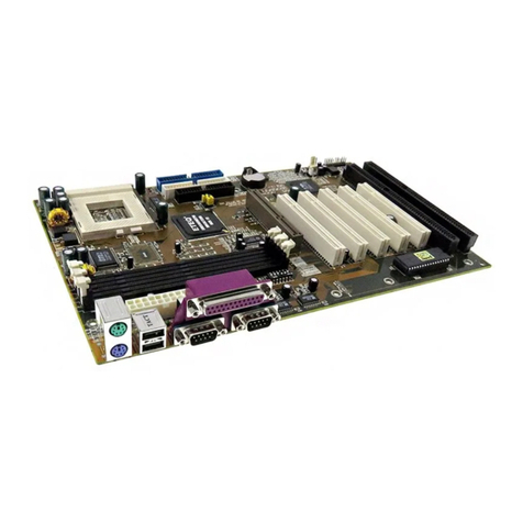
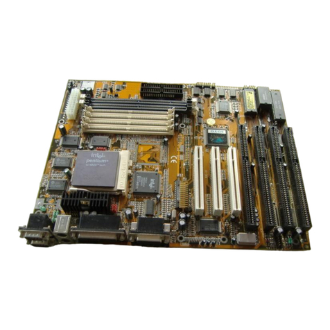
SOYO SY-6BB V1.0 User manual

SY-6BB V1.0
Mainboard
Quick Start Guide
FC
CTested To Comply
With FCC Standards
FOR HOME OR OFFICE USE
POST CONSUMER
RECYCLED PAPER
100%
Hardware
Installation
Quick BIOS
Setup
Introduction
The SOYO CD

SOYO™
2
SY-6BB V1.0 Mainboard
Pentium
®
II processor & Celeron
TM
processor
82440 BX AGP/PCI Mainboard
66&100MHz Front Side Bus supported
AT/ATX Power Connectors
Copyright © 1998 by Soyo Computer Inc.
Trademarks:
Soyo is a registered trademark of Soyo Computer Inc. All trademarks are the property of their
owners.
Product Rights:
Product and corporate names mentioned in this publication are used for identification purposes
only and may be registered trademarks or copyrights of their respective companies.
Copyright Notice:
All rights reserved. This manual is copyrighted by Soyo Computer Inc. You may not reproduce,
transmit, transcribe, store in a retrieval system, or translate into any language, in any form or by
any means, electronic, mechanical, magnetic, optical, chemical, manual or otherwise, any part of
this publication without express written permission of Soyo Computer Inc.
Disclaimer:
Soyo Computer Inc. makes no representations or warranties regarding the contents of this
manual. We reserve the right to revise the manual or make changes in the specifications of the
product described within it at any time without notice and without obligation to notify any
person of such revision or change. The information contained in this manual is provided for
general use by our customers. Our customers should be aware that the personal computer field is
the subject of many patents. Our customers should ensure that their use of our products does not
infringe upon any patents. It is the policy of Soyo Computer Inc. to respect the valid patent rights
of third parties and not to infringe upon or assist others to infringe upon such rights.
Restricted Rights Legend:
Use, duplication, or disclosure by the Government is subject to restrictions set forth in
subparagraph (c)(1)(ii) of the Rights in Technical Data and Computer Software clause at
252.277-7013.
About This Guide:
This Quick Start Guide is for assisting system manufacturers and end users in setting up and
installing the mainboard. Information in this guide has been carefully checked for reliability;
however, no guarantee is given as to the correctness of the contents. The information in this
document is subject to change without notice.
If you need any further information, please visit our Web Site on the Internet. The address is
"http://www.soyo.com.tw".
6BB QSG Version 2.0 - Edition: September 1998
*Thesespecificationsaresubjecttochangewithoutnotice

SY-6BB V1.0
Quick Start Guide
3
Introduction
1
1
Introduction
Congratulationsonyourpurchaseofthe
SY-6BBV1.0
Mainboard.ThisQuickStartGuide
describesthestepsforinstallingandsettingupyournewmainboard.
Thisguideisdesignedforalluserstoprovidethebasicstepsof mainboardsettingand
operation.Forfurtherinformation, pleasereferto SY-6BBV1.0MainboardUser'sGuideand
TechnicalReferenceonlinemanualincludedontheCD-ROMpackedwithyourmainboard.
Unpacking
*Ifyourboardcomeswithadriverdiscandapapermanual,theQuickStartGuideandtheCD-ROMarenotincludedinthepackage.
Whenunpackingthemainboard,checkforthefollowingitems:
u
TheSY-6BBV1.0 82440BX AGP/PCI Mainboard
u
ThisQuickStartGuide
u
TheInstallation CD-ROM
u
TheCPURetentionSet
u
OneIDEDeviceFlat Cable
u
OneFloppyDiskDriveFlatCable
u
Onedual25-pinparallelwith25-pinflatcableand9-pin
serialwith9-pinflatcableexternalconnector
u
Onedual6-pinPS/2mouseconnectorwith6-pinflatcable
and9-pinserialconnectorwith9-pinflatcable

SY-6BB V1.0 Quick Start Guide
4
Introduction
SY-6BB V1.0 Mainboard Layout
Key Features
Ø
SupportsIntelPentium
®
IIprocessor
(233-550MHz)Celeron
TM
processors
(266-366MHz)
Ø
Auto-detectCPUvoltage
Ø
PC97,ACPI,UltraDMA/33MHz
Ø
Power-onbymodemoralarm
Ø
SupportsWake-On-LAN(WOL)
Ø
SupportsPower-OnbyKeyboard
Ø
Supportsonboardhardwaremonitoring
andincludes Hardware Doctor™utility
Ø
SupportsCreativeSB-LINK™(PC-PCI)
forPCIaudiocard
Ø
1x32-bitAGPslot
Ø
3x32-bitbusmasteringPCIslots
Ø
1xIrDAport
Ø
Supportsmultiple-bootfunction
Ø
DMIutility
Ø
AT/ATXpowerconnectors
Flash BIOS
JP44
IR1
5
1
JP5 1
3
3V Lithium
Battery
CHAFAN
SB-LINK™
Intel®
82371 EB
Intel®
82443 BX
AGP Slot
CPUFAN
PCI Slot #1
PCI Slot #2
PCI Slot #3
ISA Slot #1
ISA Slot #2
ISA Slot #3
DIMM 1
DIMM 2
DIMM 3
IDE 1IDE 2
Slot 1 for
Pentium®II Processor
PRT 1
COM 1
COM 2 FDC
ITE8671
KB
Connector
PS/2 Mouse
Connector
ATX Power
AT Power
Speaker
Keylock
Power
LED
Reset
PWRBT
Turbo
LED
HDD LED
_
+
1 1
1
1
1
11
JP50
1
3
CMOS Clear
Jumper
WOL
Header
1
4
5
USB
8
SW1
(PC-PCI)

SY-6BB V1.0
Quick Start Guide
5
Hardware
Installation
2
2
Installation
Toavoiddamagetoyourmainboard,followthesesimpleruleswhile
handlingthisequipment:
l
Beforehandlingthemainboard,groundyourselfbygraspinganunpaintedportionof
thesystem'smetalchassis.
l
Removethemainboardfromitsanti-staticpackaging.Holditbytheedgesandavoid
touchingitscomponents.
l
Checkthemainboardfordamage.Ifanychipappearsloose,presscarefullytoseatit
firmlyinitssocket.
Followthedirectionsinthissectiondesignedtoguideyouthroughaquickandcorrect
installationofyournew
SY-6BBV1.0
Mainboard.Fordetailedinformation,pleasereferto
SY-6BBV1.0MainboardUser'sguideandTechnical Reference onlinemanualincludedon
theCD-ROMpackedwithyourmainboard.
PREPARATIONS
Gatherandprepareallthenecessaryhardwareequipmenttocompletetheinstallation
successfully:
u
Pentium
®
II
processorwithbuilt-inCPUcoolingfan(boxedtype)
u
SDRAMmodule
u
Computercaseandchassiswithadequatepowersupplyunit
u
Monitor
u
PS/2Keyboard
u
PointingDevice
u
VGACard
u
SoundCard(optional)
u
Speaker(s)(optional)
u
DiskDrives:HDD,CD-ROM,Floppydrive…
u
ExternalPeripherals:Printer,Plotter,andModem-(optional)
u
InternalPeripherals:ModemandLANcards(optional)

SY-6BB V1.0
Quick Start Guide
6
Hardware
Installation
Install the Mainboard
Followthestepsbelowinordertoperformtheinstallationofyournew
SY-6BBV1.0
Mainboard.
Step 1. Install the CPU
Mark your CPU Frequency:
RecordtheworkingfrequencyofyourCPU
thatshouldbeclearlymarkedontheCPUcover.
233MHz (66 x 3.5) 333MHz (66 x 5.0) 450MHz (100 x 4.5)
266MHz (66 x 4.0) 350MHz (100 x 3.5) 500MHz (100 x 5.0)
300MHz (66 x 4.5) 400MHz (100 x 4.0) 550MHz (100 x 5.5)
CPU Mount Procedure:
TomountthePentium
®
IIprocessorthatyouhave
purchasedseparately,followthese instructions.
1
Unpack the Retention Kit 2
Position the Mainboard 3
Insert the Screws
4
Install the Supporting Base
5
Install the Retention Clip 6
Install the CPU
7
Install the Support Clip 8
Insert the Latches 9
Remember to connect the CPU
Cooling Fan to the CPUFAN
power connector on the
mainboard.
Supporting Base
Support Clip
Screws (x2)
Retention Clip
Latches (x2)
Slot 1
HeatSink
ATXPower
Larger Pinhole

SY-6BB V1.0
Quick Start Guide
7
Hardware
Installation
Step 2. Make Connections to the Mainboard
Thissectiontellshowtoconnectinternalperipheralsandpowersupplytothemainboard.
InternalperipheralsincludeIDEdevices(HDD,CD-ROM),FloppyDiskDrive,Chassis Fan,
FrontPanelDevices(TurboLED,InternalSpeaker,ResetButton,IDELED,and KeyLock
Switch.),Wake-On-LANcard,VGAcard,SoundCard,andotherdevices.
FormoredetailsonhowtoconnectinternalandexternalperipheralstoyournewSY-6BB
V1.0Mainboard,pleasereferto SY-6BBV1.0MainboardUser'sGuideandTechnical
ReferenceonlinemanualonCD-ROM.
Connectors and Plug-ins
PCI Audio Card Header: SB-Link™(PC-PCI) Wake-On-LAN Header: JP44
Connect the SB-Link™(PC-PCI) cable from your
PCI audio card to this header. Connect the WOL cable from
your LAN card to JP44.
CPU Cooling Fan: CPUFAN
Connect the CPU cooling fan cable to the CPUFAN power connector.
Chassis Fan: CHAFAN
Connect the case cooling fan cable to the CHAFAN power connector.
USB TB LED SPK
Plug your USB devices
to this header. Connect your Turbo LED
cable to this header. Connect the speaker cable to
this header.
RESET IDE LED KB-LOCK
Connect the reset button
to this header. Connect the IDE device
LED to this header. Connect the Power LED and the
KB Lock switch to this header.
IrDA (Infrared Device Header): IR AT Power Cable
Connect the cable from your IrDA device
to this header. Connect the AT Power cable to this
connector. If you use AT power supply.
ATX Power On/Off: PWRBT ATX Power Supply: ATX PW
Connect your power switch to this
header (momentary switch type).
To turn off the system,
please press this switch and
hold down for longer than
4 seconds.
Attach the ATX Power cable to this connector. If
you use ATX power supply.
When using the Keyboard Wake-Up
function, please make sure the ATX
power supply can take at least 720mA
load on the 5V Standby lead (5VSB) to
meet the standard ATX specifications.
SY-6BB V1.0
Quick Start Guide
8
Hardware
Installation
Step 3. Configure Memory
YourboardcomeswiththreeDIMMsockets,providingsupportforupto768MBofmain
memoryusingDIMMmodulesfrom8MBto256MB.For66MHzfrontsidebusCPUsuse
12nsorfastermemory;for100MHzfrontsidebusCPUsuse8ns(100MHz,PC100
compliant)memory.
Memory Configuration Table
Number of
Memory Modules DIMM 1 DIMM 2 DIMM 3
13rd
22nd 3rd
31st 2nd 3rd
RAM Type SDRAM
Memory Module
Size (MB) 8/16/32/64/128/256 Mbytes
Note:(1) 256 MB memory modules available on PC registered DIMM only.
(2) Always install memory modules in the order prescribed in this table.
(3) Do not install unbuffered and registered memory modules together.
Important:
ItisofprimeimportancethatyouinstallDIMMmodulesasoutlinedinthetable
aboveinordertopreservesignalintegrityon100MHzfrontsidebussystems.
Step 4. Set SW1 for power up FSB clock and AGP bus clock.
SW1isusedtoadjustAGPbusclockfrequencydependingonthevalueofthefrontsidebus
(FSB)clock,alsothesettingoftheSW1determinesthepowerupFSBclockwhichwill
remaineffectiveuntiltheBIOSsettheFSBclocktotheCMOSsetting.
SW1 Setting Power up FSB Clock AGP Clock
66MHz AGP Clock
= FSB Clock ÷1
100MHz AGP Clock
= FSB Clock ÷1.5
Note:Thespecification ofmaximumAGP bus Clockfrequencyis 66.6MHz.
∗
SetSW1toopenwhenyouuseaFSB100MHzCPUsuchas350MHz,400MHz,
450MHz,or500MHz.
∗
SetSW1toclosewhenyouuseaFSB66MHzCPUsuchas233MHz,266MHz,
300MHz,333MHz,or366Mhzonlyfor Celeron.
∗
SetSW1toopenwhenyouuseaFSB66MHzbutwanttooverclocktheFSBclockto
100MHzviatheBIOSsetting.

SY-6BB V1.0
Quick Start Guide
9
Hardware
Installation
Step 5. Set the CPU Frequency
YoudonotneedtosetanyjumperfortheCPUfrequency.Instead,CPUsettingarechanged
throughtheBIOS[CHIPSETFEATURESSETUP].Pleasereferto Chapter3-QuickBIOS
SetupfordetailsonhowtosetthePentium
®
IIprocessorfrequency.
Step 6. Enable/Disable Power-On by Keyboard (JP50)
YoucanchoosetoenablethePower-OnbyKeyboardfunctionbyshortingpin1-2onjumper
JP50,otherwise,shortpin2-3todisablethisfunction.
Power-On by
Keyboard Enable Disable
JP50 Setting
Short pin 2-3 to enable the
Power-On by Keyboard function. Short pin 1-2 to disable the
Power-On by Keyboard function.
Important: When using the Power-On by Keyboard function, please make sure the
ATX power supply can take at least 720mAmp load on the 5V Standby lead (5VSB)
to meet the standard ATX specification.
Step 7. Clear CMOS Data (JP5)
CleartheCMOSmemorybymomentarilyshortingpin2-3onjumperJP5foratleast5
seconds,andthenbyshortingpin1-2toretainnewsettings. Thisjumpercanbeeasily
identifiedbyitswhitecoloredcap.
CMOS Clearing Clear CMOS Data Retain CMOS Data
JP5 Setting Short pin 2-3 for
at least 5 seconds
to clear the CMOS.
Short pin 1-2
to retain the
new settings.
Note: You must unplug the ATX power cable from the ATX power connector when
performing the CMOS Clear operation.
3
2
1
3
2
1
3
2
1
3
2
1

SY-6BB V1.0
Quick Start Guide
10
Hardware
Installation
Note on Over-clocking Capability
TheSY-6BBV1.0mainboardprovidesover-clockingcapability.Duetotheover-
clockingsettingyoursystemmayfailtobootuporhangduringruntime.Ifthisoccurs,
pleaseperformthefollowingstepstorecoveryoursystemfromtheabnormalsituation:
1.
Turnoffsystempower(IfyouuseaATXpowersupply,sometimesyouhavetopress
thepowerbuttonformorethen4secondstoshutdownthesystem)
2.
SettheSW1toshortifyouuseaFSB66MHzCPU
3.
Pressandholddownthe<Insert>keywhileturningonthesystempower.Keep
holdingdownthe<Insert>keyuntilyouseethemessageoftheCPUtypeand
frequency(133MHzor200MHz)appearonscreen
4.
Pressthe<Del>keyduringthesystemdiagnosticcheckstoentertheAwardBIOS
Setupprogram
5.
FromtheBIOSmainmenu,select[CHIPSETFEATURESSETUP]andmovethe
cursortothe[CPUFrequency]fieldtosettheproperworkingfrequency
6.
Select[Save&ExitSETUP]andpress<Enter>tosavetheconfigurationtothe
CMOSmemory,andcontinuethebootsequence
Note: SOYOdoesnotguaranteesystemstabilityiftheuseroverclocksthesystem.
Anymalfunctions dueto over-clocking arenot coveredbythewarranty.

SY-6BB V1.0
Quick Start Guide
11
Quick BIOS
Setup
3
3
Quick BIOS Setup
ThismainboarddoesnotuseanyhardwarejumperstosettheCPUfrequency.Instead,
CPUsettingsaresoftwareconfigurablewiththeBIOS
[CHIPSETFEATURESSETUP].
Afterthehardwareinstallationiscomplete,turnthepowerswitchon, thenpress the
<DEL>
key
duringthesystemdiagnostic checksto entertheAwardBIOSSetupprogram.The CMOS
SETUPUTILITYwilldisplayonscreen.Then,followthesestepsto configurethe CPUsettings.
Step 1. Select [LOAD SETUP DEFAULT]
Selectthe“LOADSETUPDEFAULT”menuandtype “Y”attheprompttoloadtheBIOS
optimalsetup.
Step 2. Select [STANDARD CMOS SETUP]
Set[Date/Time]and[Floppydrivetype],thenset[Hard DiskType]to “Auto”.
Step 3. Select [CHIPSET FEATURES SETUP]
Movethecursortothe
[CPUSpeed]
fieldtosettheCPUfrequency.
Available[CPUSpeed] settingsonyourSY-6BBV1.0 Mainboardaredetailedinthe
followingtable.Ifyousetthisfieldto[Manual],youarethenrequiredtofillinthenexttwo
consecutivefields:(1)the[CPUHostClock],and(2)the[CPURatio].
CPU Speed
233MHz (66 x 3.5) 400MHz (100 x 4.0)
266MHz (66 x 4.0) 450MHz (100 x 4.5)
300MHz (66 x 4.5) 500MHz (100 x 5.0)
333MHz (66 x 5.0) 550MHz (100 x 5.5)
350MHz (100 x 3.5)
Select the working frequency of
your Pentium®
II processor among
these preset values.
Note: Mark the checkbox that
corresponds to the working
frequency of your Pentium®
II
processor in case the CMOS
configuration should be lost.
Step 4. Select [SAVE & EXIT SETUP]
Press
<Enter>
tosavethenewconfigurationtotheCMOSmemory,andcontinuetheboot
sequence.

SY-6BB V1.0 Quick Start Guide
12
The SOYO CD
4
4
The SOYO CD
YourSY-6BBV1.0MainboardcomeswithaCD-ROMlabeled"SOYOCD."TheSOYOCD
containstheuser'smanualfileforyournewmainboard,the driverssoftwareavailablefor
installation,andadatabaseinHTMLformatwithinformationonSOYO mainboardsand
otherproducts.
Step 1. Insert the SOYO CD into the CD-ROM drive
TheSOYOCDwillauto-run,andtheSOYOCDStartUpMenuwilldisplayasshownbelow.
(SOYOCD Start UpProgram Menu)
TheSOYOCDStartUpProgramautomaticallydetectswhichSOYOmainboardyouown
anddisplaysthecorrespondingmodelname.
Step 2. Read SOYO [model name] Manual
Clickthe
Read Manual
buttontoopentheuser'smanualfileofyourmainboard.

SY-6BB V1.0
Quick Start Guide
13
The SOYO CD
PleasenotethatiftheStartUpprogramwasunabletodeterminewhichSOYOmainboard
youown,themanualselectionmenuwillpopup,asshownbelow.Thenselecttheuser's
manualfilethatcorrespondstoyourmainboardmodelnameandclick
OK.
(ManualSelection Menu)
Theuser'smanualfilesincludedontheSOYOCDcanbereadinPDF(Postscript
Document)format.InordertoreadaPDFfile,theappropriateAcrobatReadersoftware
mustbeinstalledinyoursystem.
Note:
TheStartUpprogramautomaticallydetectsiftheAcrobatReaderutilityisalready
presentinyoursystem,andotherwisepromptsyouonwhetherornotyouwanttoinstallit.
YoumustinstalltheAcrobatReaderutilitytobeabletoreadtheuser'smanualfile.Follow
theinstructionsonyourscreenduringinstallation,thenoncetheinstallationiscompleted,
restartyoursystemandre-runtheSOYOCD.
Step 3. Install Drivers
Clickthe
Install Drivers
buttontodisplaythelistof driverssoftwarethatcanbeinstalledwith
yourmainboard.TheStartUpprogramdisplaysthedriversavailablefortheparticularmodel
ofmainboardyouown.Werecommendthatyouonlyinstallthosedrivers.
However,todisplaythe listofall driverssoftwareavailable withSOYO mainboards,clickthe
DisplayalldriversontheSOYOCD
button.Pleasemakesuretoinstallonlythedrivers
adaptedtoyoursystem,orotherwisethiscausesystemmalfunctions.
Please select your manual In the box below
and click OK.
SOYO CD Manuals
6BB OK Back

SY-6BB V1.0 Quick Start Guide
14
The SOYO CD
Thefollowing drivers areavailable forWindows95
(DriverInstallation Menu)
Thefollowing drivers areavailable forWindows98
(DriverInstallation Menu)

SY-6BB V1.0
Quick Start Guide
15
The SOYO CD
Selectwhichdriveryouwanttoinstallandclick
OK,
orclick
Cancel
toabortthedriver
installationandreturntothemainmenu.
Note:
Onceyouhaveselectedadriver,thesystemwillautomaticallyexittheSOYOCDto
beginthedriverinstallationprogram.Whentheinstallationiscomplete,mostdriversrequire
torestartyoursystembeforetheycanbecomeactive.
Step 4. Enter the SOYO CD
Clickthe
EnterSOYO CD
buttontoentertheSOYOHTMLdatabase.TheStartUp
programwillactivatethedefaultHTMLbrowserinstalledonyoursystem(forexample,
InternetExplorerorNetscape)tovisualizethecontentsoftheSOYOCD.
TheSOYOCDcontainsusefulinformationaboutyourmainboardandotherSOYOproducts
availableinasmanyaselevendifferentlanguages.Foryourconvenience,thisinformationis
availableinHTMLformat,similartotheformatwidelyusedontheInternet.
(SOYOCD HTMLDatabase inEnglish*)
(*Thelistofmenuoptionsmayvarybetweenlanguages)
Note:
IfnoHTMLbrowserisinstalledonyoursystem,theStartUpprogramwillpromptyou
onwhetherornotyouwouldliketoinstalltheInternetExplorer*browser.ClickYEStoinstall
theHTMLbrowser.Aftertheinstallationiscomplete,pleaserestartyoursystem.Thenre-run
theSOYOCDandyouwillbeabletobrowsetheSOYOHTMLdatabase.
(*InternetExplorerisaMicrosoftTrademark)

Edition: Sep. 1998
For Assembly
Version 2.0
6BB V1.0SERIAL
International Headquarters
SoyoComputerInc.,(Taiwan)
Tel:886-2-2290-3300
Fax:886-2-2298-3322
WebSite:http://www.soyo.com.tw
E-mail:[email protected]
USA Branch Office
SoyoTekInc.,(USA)
Tel:(408)452-7696
Fax:(408)573-7696
WebSite:http://www.soyousa.com
E-mail:[email protected]
SOYO Europe
SoyoEuropeB.V.,(Holland)
Tel:31-79-3637500
Fax:31-79-3637575
WebSite:http://www.soyo-europe.com
http://www.soyo.nl
E-mail:[email protected]
Germany Branch Office
SAATTechnologyGmbH,(Germany)
Tel:49-(0)444-204044
Fax:49-(0)444-203422
WebSites:http://www.saat.de
http://www.soyo-saat.de
http://www.soyo-saat.com
Email:[email protected]
UK Branch Office
Soyo(U.K.) Ltd.
Tel:44-(0)181-5694111
Fax:44-(0)181-5694134
WebSite:http://www.soyo.nl
E-mail:[email protected]
Japan Branch Office
SoyoComputer(Japan)
Tel:81-3-33682188
Fax:81-3-33682199
WebSite:http://www.soyo.co.jp
E-mail:[email protected]
Hong Kong Branch Office
SoyoHongKongLtd.(H.K.)
Tel:852-2710-9810
Fax:852-2710-9078
WebSite:http://www.soyo.com.hk
E-mail:[email protected]
Table of contents
Other SOYO Motherboard manuals

SOYO
SOYO SY-P4-645DX DRAGON Ultra User manual

SOYO
SOYO SY-6BA+ Use and care manual

SOYO
SOYO SY-K7V DRAGON Plus User manual

SOYO
SOYO Super 7 SY-5EMA User manual

SOYO
SOYO SY-7IZB+N User manual

SOYO
SOYO SY-P4I845GV User manual

SOYO
SOYO SY-K7VME User manual

SOYO
SOYO SY-6BB User manual

SOYO
SOYO SY-6VZA User manual

SOYO
SOYO SY-6IZA-NA User manual

SOYO
SOYO SY-7VMA-B User manual

SOYO
SOYO SY-P4IS2 User manual

SOYO
SOYO SY-7ISA+ User manual

SOYO
SOYO Motherboard SY-6BA+ IV User manual

SOYO
SOYO SY-5EMA+ User manual

SOYO
SOYO SY-7IS2 User manual

SOYO
SOYO SY-P4VDA User manual

SOYO
SOYO SY-D6IGA Use and care manual

SOYO
SOYO SY-6BA+III User manual

SOYO
SOYO DRAGON Lite SY-KT333 User manual